
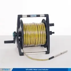
1. WATER LEVEL INDICATOR
Product Code
|
UTS-0050 |
Water Level Indicator 50 m Cable Length |
|
UTS-0052 |
Water Level Indicator 100 m Cable Length |
|
UTS-0055 |
Water Level Indicator 150 m Cable Length |
|
UTS-0058 |
Water Level Indicator 200 m Cable Length |
The Water Level Indicators (Electric Contact Meters) are portable, easy-to-use and reliable instruments for measuring water level and total depth in bore holes, wells, observation pipes, reservoirs, as well as control of pumping tests.
As soon as the measuring probe electrode touches the water surface, the signal indicator on the instrument lights up with an audible alarm. The water level can be read on the measuring tape in meters (m) and centimeters (cm).
Technical Specifications
|
Measuring Range |
50 m, 100 m, 150 m, 200 m |
|
Sensitivity |
100 m cable length - smaller than 1 cm |
|
Probe |
Chromium-Nikel plated brass Standart Version: 14 mm dia. 140 mm long Special Version: 10 mm dia. 320 mm long |
|
Cable |
Polyamide coated steel tape with transparent polyethylene covering over 2 tinned copper conductors on both sides of the steel strip. |
|
Cable Metrics |
Dimensions in millimeters (mm), centimeters (cm) and decimeters (dm) on the yellow steel strip are colored in black and meters (m) in red. |
|
Cable Construction |
Transparent, hard plastic and heat resistant. |
|
Power Supply |
3V DC, 2piece AA size pen battery. Each one 1.5V |
|
Product Code |
Dimensions |
Weight (approx.) |
|
UTS-0050 |
350x350x350 mm |
7 kg (50 m) |
|
UTS-0052 |
350x350x350 mm |
10 kg (100 m) |
|
UTS-0055 |
350x350x400 mm |
12 kg (150 m) |
|
UTS-0058 |
350x350x400 mm |
15 kg (200 m) |
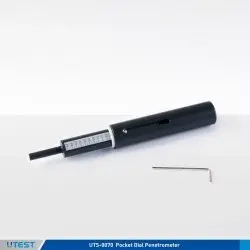
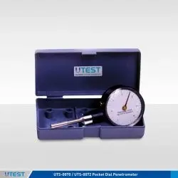
2. POCKET DIAL PENETROMETER
Product Code
|
UTS-0070 |
Pocket Dial Penetrometer, 0-6 kgf/cm2 |
|
UTS-0072 |
Pocket Dial Penetrometer, 0-14 kgf/cm2 |
|
UTS-0075 |
Pocket Dial Penetrometer, 0-6, 0-11 kgf/cm2 |
|
UTS-0078 |
Pocket Penetrometer, 0-5 kgf/cm2 |
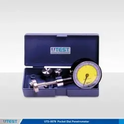
The UTS Series of Pocket Dial Penetrometers are ideal instruments to determine the penetration resistance of cohesive soil, especially when various range measurements are required.
UTS-0075 Pocket Dial Penetrometer with respect to range and plunger diameters is avaliable for specific applications.
All Dial Penetrometer models have 60 mm. Dial Diameter and designed with Peak Hold Feature.
UTS-0075 Pocket Dial Penetrometer is used for evaluating the angle of internal friction “j” of sandy soils and the cohesion “c” 2 in clay soils. Dual scale: 0-6 kgf/cm for 6.35 mm diameter 2 plunger and 0-11 kgf/cm.
The UTS-0078 Pocket Penetrometer is a portable and easy-touse equipment to perform field classification of cohesive soils in terms of consistency, shear strength and approximate unconfined compressive strength.
|
Product Code |
Range (kg/cm') |
Plunger Dia. |
Dimensions |
Weigth (approx.) |
|
UTS-0070 |
0-6 |
6.35 |
80x150x40 mm |
0,20 kg |
|
UTS-0072 |
0-14 |
6.35 |
80x150x40 mm |
0,20 kg |
|
UTS-0075 |
0-6, 0-11 |
6.35-10-15-20-25 |
80x150x40 mm |
0,20 kg |
|
UTS-0078 |
0-5 |
6.35 |
30x180x30 mm |
0,10 kg |
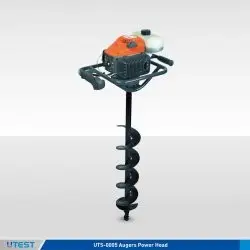
3. AUGERS POWER HEAD
Product Code
|
UTS-0005 |
Augers Power Head |
|
UTS-0008 |
Single Flute Bit Ø:80x1000 mm |
|
UTS-0010 |
Single Flute Bit Ø:100x1000 mm |
|
UTS-0015 |
Single Flute Bit Ø:150x1000 mm |
|
UTS-0020 |
Single Flute Bit Ø:200x1000 mm |
Standards
ASTM D420, D1452; AASHTO T86, T202; CNR a. VI n.25
Used in conjunction with sampling tubes to obtain disturbed or undisturbed soil samples. The flute bits with 80-100-150-200 mm diameters should be ordered separately.
|
UTS-0005 Properties |
|
|
Motor Power |
1,6 kW |
|
Cylinder Volume |
50,2 cc |
|
Reduction Ratio |
40:1 |
|
Product Code |
Dimensions |
Weigth |
|
UTS-0005 |
580x1300x580 mm |
10 kg |
|
UTS-0008 |
70x80x290 mm |
1 kg |
|
UTS-0010 |
90x100x300 mm |
1,50 kg |
|
UTS-0015 |
120x150x320 mm |
2 kg |
|
UTS-0020 |
150x200x350 mm |
4 kg |
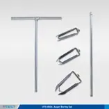
4. HAND OPERATED AUGER BORING SET
Product Code
|
UTS-0024 |
Hand Operated Auger Boring Set |
|
UTS-0026 |
Extension Rod for UTS-0024, 1 meter |
|
UTS-0027 |
T-Handle with 1 m Rod |
|
UTS-0028 |
Auger Head Set, Ø:80 mm Ø:100 mm and Ø:150 mm |
UTS-0024 Hand Boring and Sampling Set for augering down to a depth of 5 meters.
The UTS-0024 Hand Operated Auger Boring Set consists of a T-Handle with 1 m Rod, 1 m Extension Rod, 80 mm, 100 mm and 150 mm diameter Auger Heads.
|
Dimensions |
400x1200x250 mm |
|
Weigth (approx.) |
12 kg |
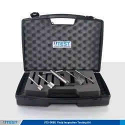
5. FIELD INSPECTION TESTING KIT
Product Code
|
UTS-0080 |
Field Inspection Testing Kit |
|
UTS-0082 |
Field Inspection Pocket Vane Tester |
|
UTS-0083 |
Extension Rod for UTS-0082 |
|
UTS-0084 |
Heavy Duty Pocket Penetrometer, 0-10 kgf/cm² |
Standards
ASTM D2573
The UTS-0080 Field Inspection Testing Kit is ideal for geotechnicians, geologists and agronomists. It consists of the UTS-0084 Pocket Penetrometer and of the UTS-0082 Field Inspection Pocket Vane Tester. The instrument is contained in a practical carrying case.
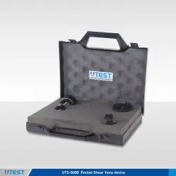
6. POCKET SHEAR VANE DEVICE
Product Code
|
UTS-0088 |
Pocket Shear Vane Device |
The UTS-0088 Pocket Shear Vane Device is a practical equipment for determining the shear strength of cohesive soils. It is widely used to perform onsite measurements of excavations covering trenches and test pits, thin-wall or split core samples, by providing a quick and efficient method for shear strength measurements and it is also suitable for laboratory usage. Pocket Shear Vane Device is supplied in a plastic carrying case.
|
Vane Type |
Range |
|
Standard 25 mm Diameter Vane |
0-10 N/cm² |
|
Sensitive Vane Adaptor |
0-2 N/cm² |
|
High Capacity Vane Adaptor |
0-25 N/cm² |
|
Dimensions |
220x230x50 mm |
|
Weight (approx.) |
0,30 kg |
7. TRL DYNAMIC CONE PENETROMETER

Product Code
|
UTS-0095 |
TRL Dynamic Cone Penetrometer (DCP) |
Standards
ASTM D 6951
The UTS-0095 TRL Dynamic Cone Penetrometer is used for the rapid, in situ measurement of structural properties of existing road pavement constructed with unbound materials.
The design of the DCP is similar to that described by Kleyn, Maree and Savage (1982); it incorporates an 8 kg weight dropping through a height of 575 mm and 60° cone having a diameter of 20 mm. with the standard DCP measurements can be made down to a depth of approximately 850 mm or when extension shafts are used to a recommended maximum depth of 2 m.
Readings are usually taken after a set number of blows, changing the number according to the strength of the layer being penetrated. A typical test takes only a few minutes, therefore the instrument provides a very efficient method of obtaining information that would normally require the digging of test pits.
The penetration hammer assembly consists of 8 kg hammer, hammer shaft, anvil with plastic plate coupling for ruler and handle.
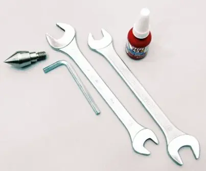
The TRL Dynamic Cone Penetrometer is supplied complete with;
- A hammer assembly,
- Penetration rod,
- 2 piece 60° cone,
- Metal plate coupling for ruler,
- Segmented adaptor for extension rods,
- Segmented upper extension rod,
- Segmented lower extension rod,
- 2 piece 13-17mm AF spanners,
- 3mm AF hex wrench,
- Tommy bar,
- A bottle of adhesive,10cc,
- Users Manual
- Steel ruler,
- Carrying Case, heavy-duty wooden
|
Dimensions |
220x1200x170 mm |
|
Weight (approx.) |
24 kg |
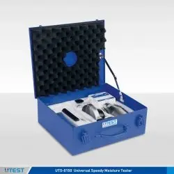
8. UNIVERSAL SPEEDY MOISTURE TESTER
Product Code
|
UTS-0150 |
Universal Speedy Moisture Tester |
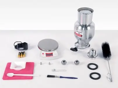
UTS-0150 Universal Speedy Moisture Tester is used to determine the moisture content of soils, sand and fine aggregates in the field. It is an easy and portable method. The amount of gas, which is given off when water and calcium carbide are mixed and react, is directly proportional to the amount of water present in the sample and results in percentage moisture are taken from a pressure gauge.
The Universal Speedy Moisture Tester is supplied complete with;
- Calibrated pressure bottle with surface thermometer
- Mechanical manometer up to 1,6 bar direct reading of humidity for the weights 20g, 50g and 100g
- Steel ball set (Ø10 mm/3 pcs. and Ø5,5 mm/1 pcs.)
- Digital sample scale up to 200g
- 25 normed carbide ampoules with 7g calcium carbide according to DIN 18560-4
- Other measurement accessories
- Double-walled plastic case
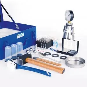
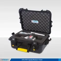
9. SPEEDY MOISTURE TESTER
Product Code
|
UTS-0155 |
Speedy Moisture Tester |
Standards
ASTM D4944; AASHTO T217
The UTS-0155 Speedy Moisture Tester is used to determine the moisture content of soils, sand and fine aggregates in the field. It is an easy and portable method. The amount of gas, which is given off when water and calcium carbide are mixed and react, is directly proportional to the amount of water present in the sample and results in percentage moisture are taken from a pressure gauge.
These model is used for moisture determination of a 20 g specimen with 20% maximum moisture content. UTS-0155 Speedy Moisture Tester does not include Calcium Carbide Powder.
The Speedy Moisture Tester is supplied complete with;
- Vessel with Gauge
- Digital Scale
- Scoop
- Cleaning Brush
- Cleaning Cloth
- Two Steel Pulverizing Balls
- Plastic Case
|
Dimensions |
210x370x530 mm (case) |
|
Weight (approx.) |
7 kg |
10. HAND OPERATED HYDRAULIC SPECIMEN EXTRUDER
Product Code
|
UTGE-0082 |
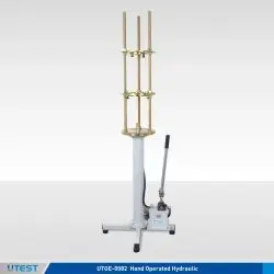
Hand Operated Hydraulic Specimen Extruder, Vertical Type, 60 kN Capacity |
Standards
EN 13286-2, 13286-47, 12697-30; AASHTO T134, T180, T193,
T245; ASTM D698, D1557, D1883, D1559; BS 1377-4, 1924-2,
598-107
The UTGE-0082 Hand Operated Hydraulic Extruder is designed for extruding specimens from 50 mm (2”) to 125 mm (5”) (outer dia.) shelby sample tubes and moulds such as proctor, CBR and marshall moulds.
Also useful for sampling and removing uniaxial and triaxial test specimens to/from the cutters inner dia. from 38 mm to 100 mm. The extruder has 60 kN extrusion force and 650 mm ram travel.
To remove the sample from the shelby tubes, adapter sets of different sizes in the table below should be ordered separately.
Supplied complete with;
- Adapter sets for Ø150 mm (6”) and Ø100 mm (4”) inner dia. moulds
- Flanges and head sets for Ø38 mm, Ø50 mm, Ø70 mm and 100 mm (only flange) inner dia. cutters.
|
For UTS-0082 |
||
|
UTGE-0110 |
Adaptor Set for 2" (50,8mm) Outer Dia Shelby Tubes. |
Includes a ring with 48,5mm ID. and an extruder head with Ø43,5mm. |
|
UTGE-0112 |
Adaptor Set for 2 ½” (63,5 mm) Outer Dia Shelby Tubes. |
Includes a ring with 61mm ID. and an extruder head with Ø56mm. |
|
UTGE-0114 |
Adaptor Set for 3" (75 mm) Outer Dia Shelby Tubes. |
Includes a ring with 72mm ID. and an extruder head with Ø67mm. |
|
UTGE-0116 |
Adaptor Set for 3 1/4" (83 mm) Outer Dia Shelby Tubes. |
Includes a ring with 79,5mm ID. and an extruder head with Ø74,5mm. |
|
UTGE-0118 |
Adaptor Set for 3 1/2" (88,9 mm) Outer Dia Shelby Tubes. |
Includes a ring with 85mm ID. and an extruder head with Ø80mm. |
|
UTGE-0120 |
Adaptor Set for 100 mm Outer Dia Shelby Tubes. |
Includes a ring with 96mm ID. and an extruder head with Ø91mm. |
|
UTGE-0122 |
Adaptor Set for Ø4" (101,6 mm) Outer Dia Shelby Tubes. |
Includes a ring with 97,5mm ID. and an extruder head with Ø92,5mm. |
|
UTGE-0124 |
Adaptor Set for 4 1/2" (114,3 mm) Outer Dia Shelby Tubes. |
Includes a ring with 109mm ID. and an extruder head with Ø104mm. |
|
UTGE-0125 |
Adaptor Set for 5" (125 mm) Outer Dia Shelby Tubes. |
Includes a ring with 119mm ID. and an extruder head with Ø114mm. |
|
Dimensions |
470x650x1900 mm (case) |
|
Weight (approx.) |
82 kg |
11. MOTORIZED HYDRAULIC SPECIMEN EXTRUDER, HORIZONTAL TYPE, 60 kN CAPACITY
Product Code
|
UTGE-0084 |
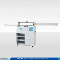
Motorized Hydraulic Specimen Extruder, Horizontal Type, 60 kN Capacity |
|
Models for 220-240V 50-60 Hz, 1ph |
UTGE-0084 |
|
Models for 110-120V 60 Hz, 1ph |
UTGE-0084-N |
Standards
EN 13286-2, 13286-47, 12697-30; AASHTO T134, T180, T193, T245;
ASTM D698, D1557, D1883, D1559; BS 1377-4, 1924-2, 598-107
The UTGE-0084 Motorized Hydraulic Extruder, Horizontal Type is designed for extruding specimens from 50 mm (2”) to 125 mm(5”) (outer dia.) shelby sample tubes and moulds such as proctor, CBR and marshall moulds. Also useful for sampling and removing uniaxial and triaxial test specimens to/from the cutters inner dia. from 38mm to 100mm.
The Extruder has 60 kN capacity and 900 mm ram travel. The hydraulic piston can be stopped at any position during the extraction.
To remove the sample from the shelby tubes, adapter sets of different sizes in the table below should be ordered separately.
The Motorized Hydraulic Extruder is supplied complete with ;
- Adapter sets for Ø100 mm (4”) and Ø150 mm (6”) inner dia. moulds
- Flanges and head sets for Ø38mm, Ø50mm, Ø70 mm and 100mm (only flange) inner dia. cutters.
|
For UTS-0084 |
||
|
UTGE-0110 |
Adaptor Set for 2" (50,8mm) Outer Dia Shelby Tubes. |
Includes a ring with 48,5mm ID. and an extruder head with Ø43,5mm. |
|
UTGE-0112 |
Adaptor Set for 2 ½” (63,5 mm) Outer Dia Shelby Tubes. |
Includes a ring with 61mm ID. and an extruder head with Ø56mm. |
|
UTGE-0114 |
Adaptor Set for 3" (75 mm) Outer Dia Shelby Tubes. |
Includes a ring with 72mm ID. and an extruder head with Ø67mm. |
|
UTGE-0116 |
Adaptor Set for 3 1/4" (83 mm) Outer Dia Shelby Tubes. |
Includes a ring with 79,5mm ID. and an extruder head with Ø74,5mm. |
|
UTGE-0118 |
Adaptor Set for 3 1/2" (88,9 mm) Outer Dia Shelby Tubes. |
Includes a ring with 85mm ID. and an extruder head with Ø80mm. |
|
UTGE-0120 |
Adaptor Set for 100 mm Outer Dia Shelby Tubes. |
Includes a ring with 96mm ID. and an extruder head with Ø91mm. |
|
UTGE-0122 |
Adaptor Set for Ø4" (101,6 mm) Outer Dia Shelby Tubes. |
Includes a ring with 97,5mm ID. and an extruder head with Ø92,5mm. |
|
UTGE-0124 |
Adaptor Set for 4 1/2" (114,3 mm) Outer Dia Shelby Tubes. |
Includes a ring with 109mm ID. and an extruder head with Ø104mm. |
|
UTGE-0125 |
Adaptor Set for 5" (125 mm) Outer Dia Shelby Tubes. |
Includes a ring with 119mm ID. and an extruder head with Ø114mm. |
|
Capacity |
60 kN |
|
Ram Travel |
900 mm |
|
Dimensions |
420x2000x1200 mm |
|
Weigth (approx.) |
195 kg |
|
Power |
750 W |
12. MARSHALL / CBR / PROCTOR SPECIMEN EXTRUDER
Product Code
|
UTGE-0080 |
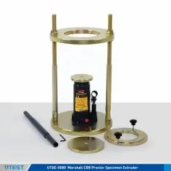
Marshall / CBR / Proctor Specimen Extruder, 30 kN Capacity |
Standards
EN 13286-2, 13286-47, 12697-30; AASHTO T134, T180, T193,
T245; ASTM D698, D1557, D1883, D1559; BS 1377-4, 1924-2,
598-107
The UTGE-0080 Extruder is designed to easily extrude specimens from marshall and CBR, standard and modified proctor moulds. The capacity of the extruder is 30 kN and is supplied complete with a manual hydraulic jack and 2 pcs. adaptor to extrude specimens from Ø100 mm (4”) and Ø150 mm (6”) dia. proctor, CBR and marshall molds.
Adaptors with different sizes should be ordered separately if required.
|
Ram Travel |
130 mm |
|
Screw Travel |
90 mm |
|
Dimensions |
280x280x510 mm |
|
Weight (approx.) |
28 kg |
13. MELTING POT
Product Code
|
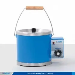
UTC-1070 |
Melting Pot, 3 L Capacity |
Standards
CEN ISO/TS 17892-2; EN 12390–3, 12390-1, 12504-1; ASTM C31, C192, C617; AASTHO R100, R39
|
Models for 220-240V 50-60 Hz, 1ph. |
UTC-1070 |
|
Models for 110-120V 60 Hz, 1ph. |
UTC-1070-N |
The Melting Pot is designed for melting capping compound, sulphur, wax and similar materials. The melted paraffin wax is used to seal soil samples and other materials.
The apparatus consists of a 3 liter capacity aluminum container in a well-lagged steel jacket, cover and a thermostatic control heating system to keep the temperature constant in the range of ambient to 200°C.
|
Dimensions |
300x340x240 mm |
|
Weigth (approx.) |
10 kg |
|
Power |
600 W |
14. Soil Lathe / Trimmer and Extruder
Product Code
|
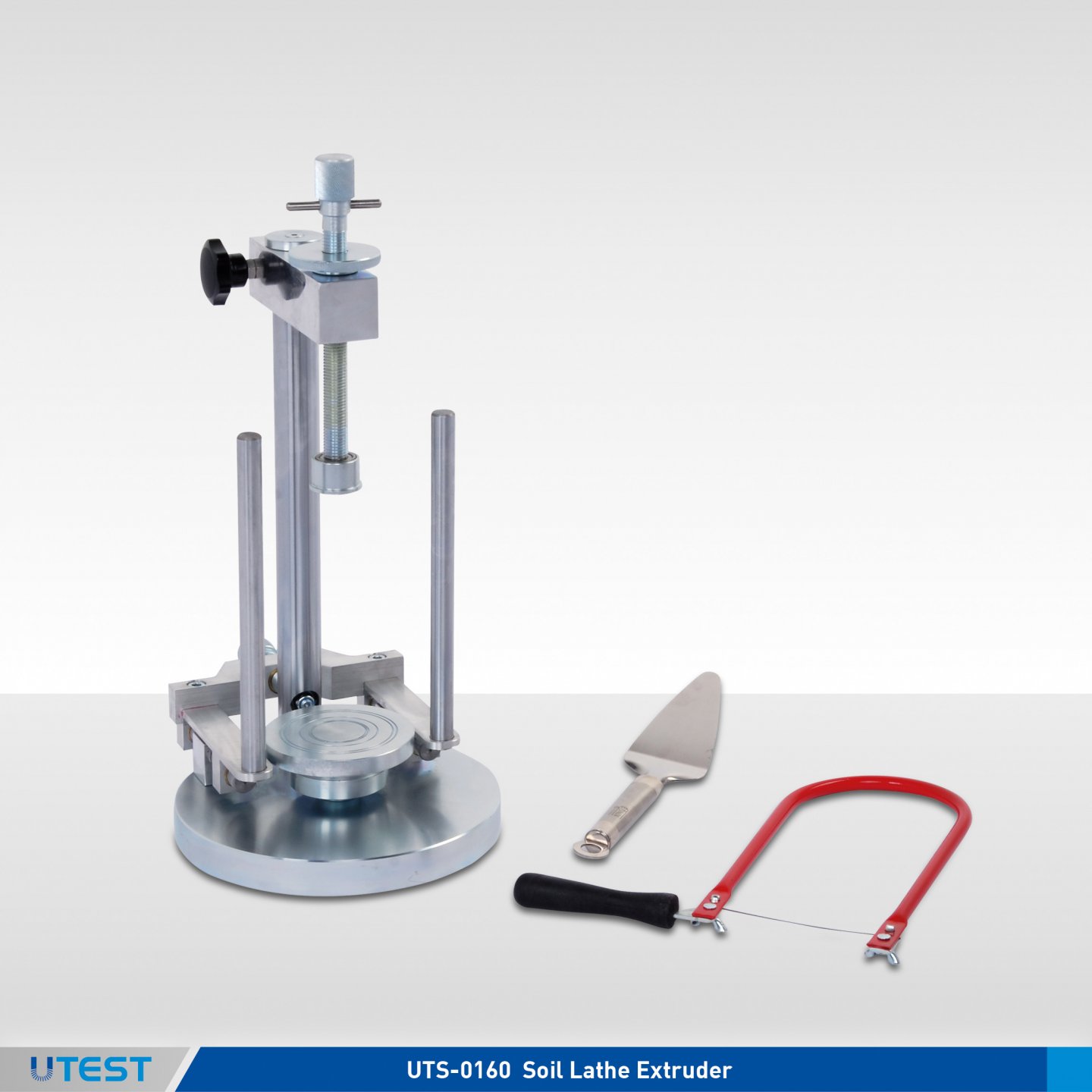
UTS-0160 |
Soil Lathe / Trimmer and Extruder |
|
UTS-0164 |
Wire Saw with one Blade |
|
UTS-0165 |
Wire Saw Blade for UTS-0164 (pack of 10) |
|
UTS-0166 |
Trimming Knife |
|
UTGG-2205 |
Porcelain Mortar with Pestle 130 mm dia |
|
UTGG-2215 |
Rubber Headed Pestle |
The UTS-0160 Soil Lathe, Trimmer and Extruder is used to extrude and trim soil samples from 35 mm to 100 mm diameter to reduce samples.
Wire Saw, Trimming Knife, Porcelain Mortar with Pestle, the Rubber Headed Pestle can be ordered separately.
Technical Specifications
|
Specimen Lathe |
35x70 mm to 100x200 mm |
|
Specimen Trimming and Extrusion |
35x70 mm to 50x100 mm |
|
Vertical Daylight |
260 mm |
|
Dimensions |
230x300x430 mm |
|
Weight (approx.) |
14 kg |
15. Laboratory Mixer
Product Code
|
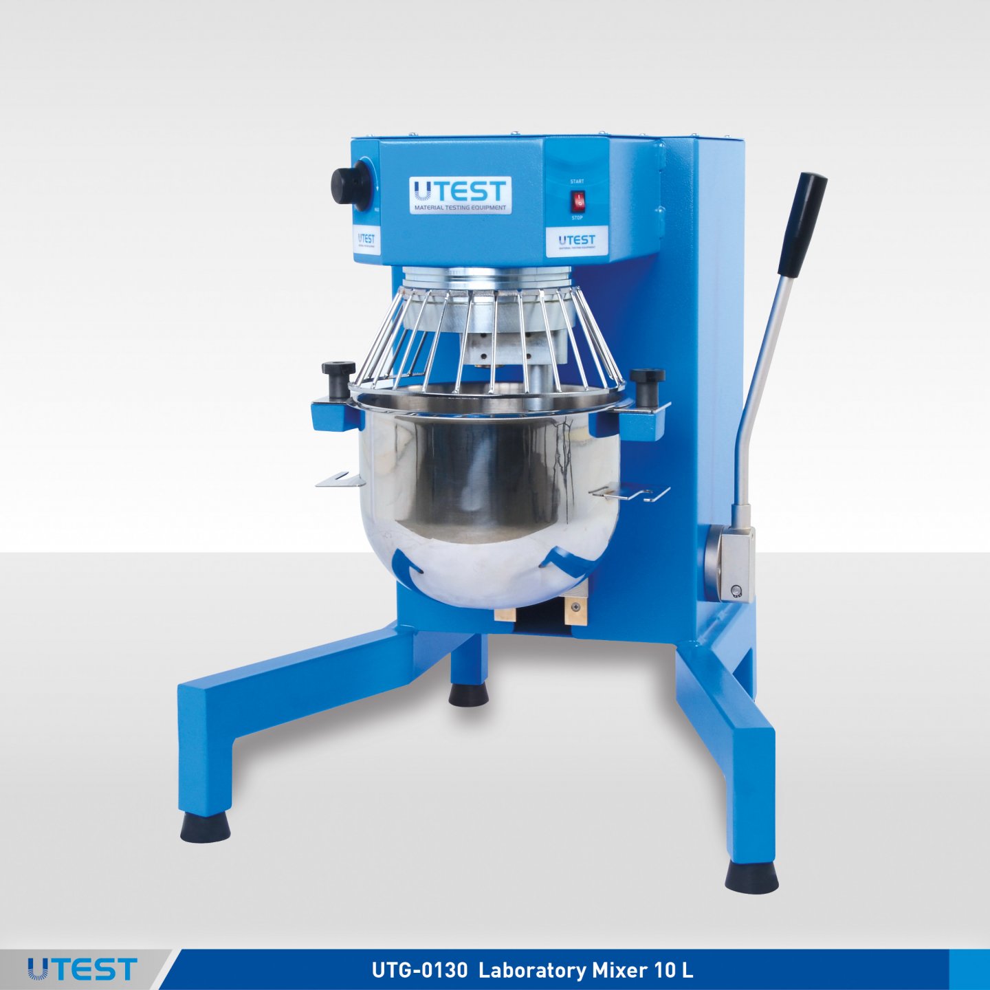
UTG-0130 |
Laboratory Mixer 10 L, 220-240 V 50-60 Hz |
|
UTAS-0187 |
Heating Mantle for UTG-0130 |
|
UTG-0131 |
Spare Bowl for UTG-0130 |
|
UTG-0132 |
Spare Whisk for UTG-0130 |
|
Models for 220-240V 50-60 Hz, 1 ph. |
UTG-0130 |
UTAS-0187 |
|
Models for 110-120V 60 Hz, 1 ph. |
UTG-0130-N |
UTAS-0187-N |
The UTG-0130 10 litre capacity Laboratory Mixer is designed for mixing of soil and asphalt samples to be used for mechanical tests such as compaction, indirect tensile, Marshall etc. The mixing head rotates at speeds of 10 to 240 r.p.m. and the whisk from 20 to 480 r.p.m. The user can adjust rotation speed between given values easily by using a control knob fitted to the front panel.
The bituminous mixture must be prepared at the prescribed temperature according to the EN standard. For this reason the mixer can be equipped with thermostatically controlled heater.
The Heating Mantle (Isomantle heater) has a digital thermostatic controller and used for heating the bituminous mixtures in the UTG-0130 up to 150°C. The Isomantle heater is supplied complete with PT100 temperature sensor.
Heating Mantle should be ordered separately.
The Laboratory Mixer is supplied complete with;
- Bowl, 10 lt Capacity Stainless Steel
- Mixing Whisk
UTG-0131 UTG-0132
|
Product Code |
UTG-0130 |
UTAS-0187 |
|
Dimensions |
600x620x700 mm |
310x380x200 mm |
|
Weight (approx.) |
65 kg |
6 kg |
|
Power |
550 W |
600 W |
16. Liquid Limit / Semi-Automatic Cone Penetrometer
Product Code
|
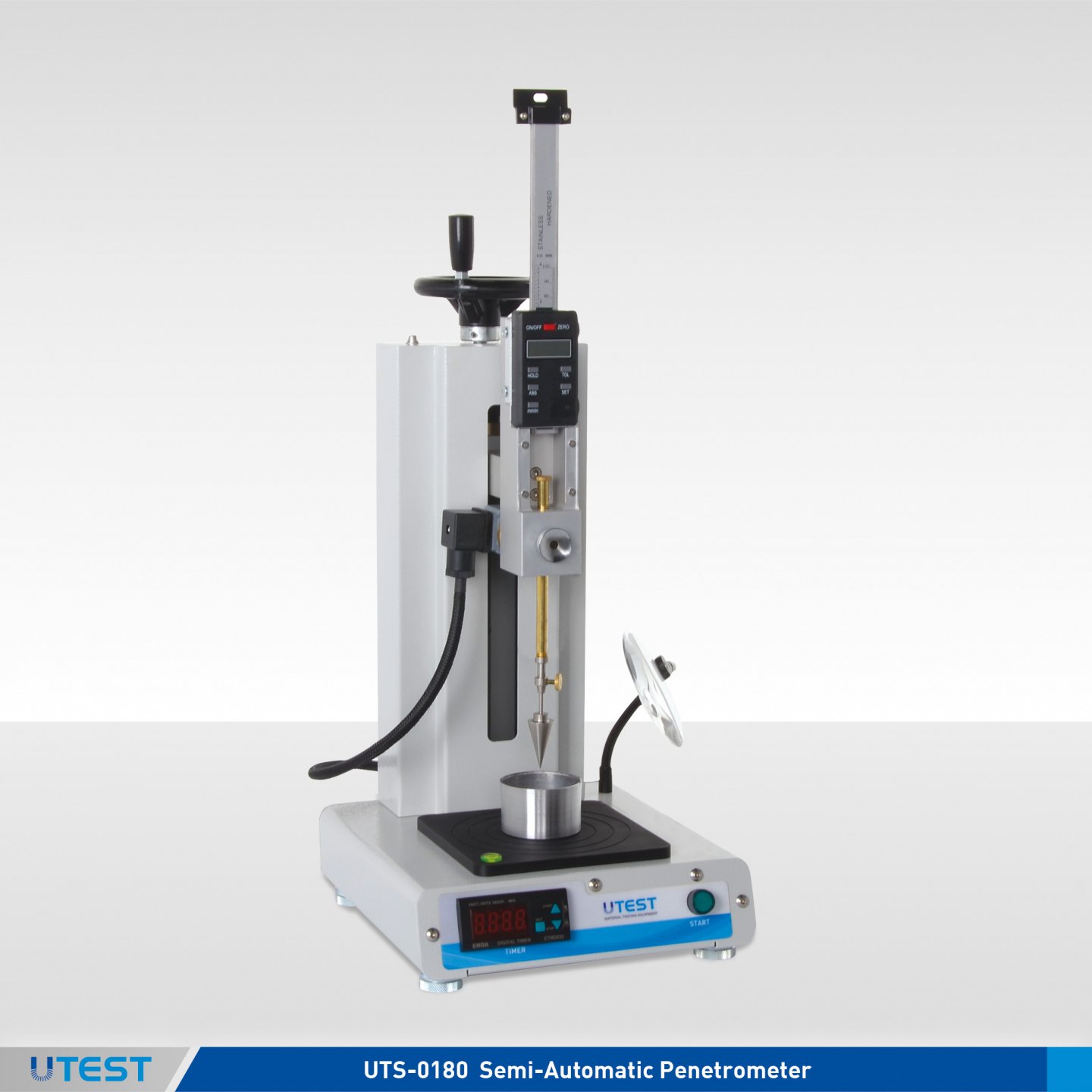
UTS-0180 |
Semi-Automatic Cone Penetrometer for Liquid Limit |
|
UTS-0182 |
Liquid Limit Penetration Test Cone, Stainless Steel, 30° and 80 g |
|
UTS-0183B |
Cone Test Gauge for 30° Angle Cone, BS |
|
UTS-0183E |
Cone Test Gauge for 30° Angle Cone, EN ISO |
|
UTS-0184 |
Liquid Limit Penetration Test Cone, Stainless Steel, 60° and 60 g |
|
UTS-0185E |
Cone Test Gauge for 60° Angle Cone, EN ISO |
|
UTS-0187E |
Liquid Limit Penetration Test Cone, Stainless Steel, 30° and 100g, EN ISO |
|
UTGH-1435 |
Penetration Sample Cup / Moisture Content Tin with Lid, 75x50mm, Aluminum |
|
UTGH-1440 |
Penetration Sample Cup / Moisture Content Tin with Lid. Ø55x30 mm, Aluminium |
|
UTGH-1442 |
Penetration Sample Cup / Moisture Content Tin with Lid. Ø55x40mm, Aluminium |
|
UTGH-1444 |
Penetration Sample Cup / Moisture Content Tin with Lid. Ø55x40mm, Stainless Steel |
|
Models for 220-240V 50-60 Hz, 1ph |
UTS-0180 |
|
Models for 110-120V 60 Hz, 1ph |
UTS-0180-N |
Standards
BS 1377:2; NF P94-052-1; EN ISO 17892-6, 17892-12
The Cone Penetrometer is used to determine the moisture content at which clay soils pass from a plastic to a liquid state and used also for the determination of undrained shear strength.
UTS-0180 Semi-Automatic Cone Penetrometer for liquid limit consists of a frame with a levelling screws and screw gear assembly with handwheel for vertical adjustment, a digital penetration measurement gauge with 0.01 mm resolution /readibility, a digital timer, a magnifying lens and a low voltage illuminator mounted on flexible arms.
Penetration time 0-99 sec. can be set up by user with the digital timer. The timer will allow the cone to free fall into the sample for the engaged time interval and then lock the cone from advancing while providing a direct reading of the test results.
Each cone supplied complete with its shaft. Penetration cone/s, cone test gauges and sample cups should be ordered seperately.
|
UTGH-1435 |
UTGH-1440 |
UTGH-1442 |
UTGH-1444 |
|
Ø (75±2) mm x h (50±2) mm |
Ø (55+2) mm x h (30±2) mm |
Ø (55+2) mm x h (40±2) mm |
Ø (55+2) mm x h (40±2) mm |
|
Dimensions |
210x220x500 mm |
|
Weight (approx.) |
14 kg |
17. Liquid Limit Casagrande Device
Product Code
|
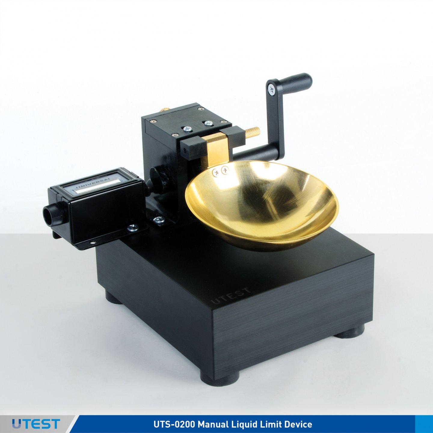
UTS-0200B |
Manual Liquid Limit Device (Casagrande), BS |
|
UTS-0202A |
Manual Liquid Limit Device (Casagrande), ASTM-AASHTO |
|
UTS-0202E |
Manual Liquid Limit Device (Casagrande), EN, ISO |
|
UTS-0210B-T |
Motorized Liquid Limit Device (Casagrande), BS, 220-240V 50 Hz, 1 ph. |
|
UTS-0212A |
Motorized Liquid Limit Device (Casagrande), ASTM-AASHTO |
|
UTS-0212E-T |
Motorized Liquid Limit Device (Casagrande), EN, ISO |
|
UTS-0215A |
Metal Grooving Tool and Gauge Block, ASTM |
|
UTS-0215E |
Metal Grooving Tool and Gauge Block, EN, ISO |
|
UTS-0216A |
Plastic Grooving Tool, ASTM |
|
UTS-0217B |
Plastic Grooving Tool, BS |
|
UTS-0218E |
Brass Grooving Tool, EN ISO |
|
UTS-0218EH |
Brass Grooving Tool, AASHTO, EN ISO |
|
UTS-0220A |
Resilience (Rebound) Tester, ASTM |
|
UTS-0221EH |
Resilience (Rebound) Tester, AASHTO, EN ISO, TS 1900-1 |
|
UTS-0225A |
Spare Brass Cup, for ASTM, AASHTO, TS 1900-1 Models |
|
UTS-0225E |
Spare Brass Cup, for EN, ISO Model |
|
Models for 220-240V 50 Hz, 1 ph. |
UTS-0212A-T |
|
Models for 110-120V 60 Hz, 1 ph. |
UTS-0212A-N |
|
Models for 220-240V 60 Hz, 1 ph. |
UTS-0212A-K |
Standards
ASTM D4318; BS 1377:2; AASHTO T89; EN ISO 17892-12
The UTEST Manual and Motorized Liquid Limit Apparatus (Casagrande) are used to determine the moisture content at which clay soils pass from plastic to liquid state.
The devices consist of an adjustable crank and cam mechanism, a blow counter and a removable brass cup fitted on the base. Different models with the same shape but with different base and cup weights are available according to the required specifications. Manual and Motorized versions are available.
The grooving tools which differ according to the preferred test standard should be ordered separately.
|
|
Manual |
Motorized |
|
Dimesions |
150x200x130 mm |
200x280x160 mm |
|
Weight (approx.) |
2 kg |
4 kg |
18. Plastic Limit Test Set
Product Code
|
UTS-0250 |
Plastic Limit Test Set |
|
UTS-0252 |
Plastic Limit Reference Rod Ø 3x100 mm |
|
UTS-0254 |
Plastic Limit Plate 300x300x10 mm, Glass |
|
UTGG-2170 |
Porcelain dish, 120 mm dia. |
|
UTGH-1433 |
Moisture content tin with lid, Aluminum, Ø:75 mm, h:30 |
|
UTGH-1495 |
Spatula, small, length:100 mm |
|
UTGP-1000 |
Piset, 250 ml |
Standards
ASTM D4318; AASHTO T90; BS 1377:2; EN, ISO 17892-12; UNE 103-104; UNI 10014
The plastic limit (PL) is defined as the lowest moisture content of a soil that will permit a sample to be rolled into threads of 3 mm diameter without the threads breaking.
The Plastic Limit Test Sets are is supplied complete with;
- A Glass Plate, 300x300x10 mm (one face ground)
- Steel Reference Rod, Ø3 mm
- Moisture Content Tins, Ø:75 mm, h:30, 6 pcs.
- Porcelain Mixing Dish, 120 mm dia.
- Spatula, 100 mm
- Carrying Case
- Piset 250 ml
|
Dimensions |
380x500x120 mm |
|
Weight (approx.) |
3,50 kg |
19. Shrinkage Limit Test Set
Product Code
|
UTS-0230 |
Shrinkage Limit Test Set |
|
UTS-0234 |
Shrinkage Prong Plate |
|
UTGH-1425 |
Moisture Content Tin with Lid, Aluminium, Ø:55 mm h:35 mm |
|
UTGH-1430 |
Moisture Content Tin with Lid, Aluminium, Ø:45 mm h:10 mm |
|
UTGG-2170 |
Porcelain dish, 120 mm dia. |
|
UTGH-1495 |
Spatula, small, length:100 mm |
|
UTGG-1005 |
Graduated glass cylinder 25 ml |
Standards
ASTM D427; AASHTO T92; UNE 103-108; UNI 10014
When the water content of a fine-grained cohesive soil is reduced below the plastic limit, shrinkage of the soil mass continues until the shrinkage limit is reached.
This method of test covers the determination of the shrinkage limit, shrinkage ratio, volumetric shrinkage and linear shrinkage.
The Shrinkage Limit Test Set is supplied complete with;
- Prong Plate
- Moisture Content Tin with Lid, aluminum, Ø:45 mm h:10 mm, 2 pcs.
- Moisture Content Tin with Lid, aluminum, Ø:55 mm h:35 mm
- Porcelain Dish, 120 mm dia.
- Spatula, 100 mm
- Graduated Glass Cylinder, 25 ml,
- Carrying Case
|
Dimensions |
280x330x80 mm |
|
Weight (approx.) |
1 kg |
20. Linear Shrinkage Mould
Product Code
|
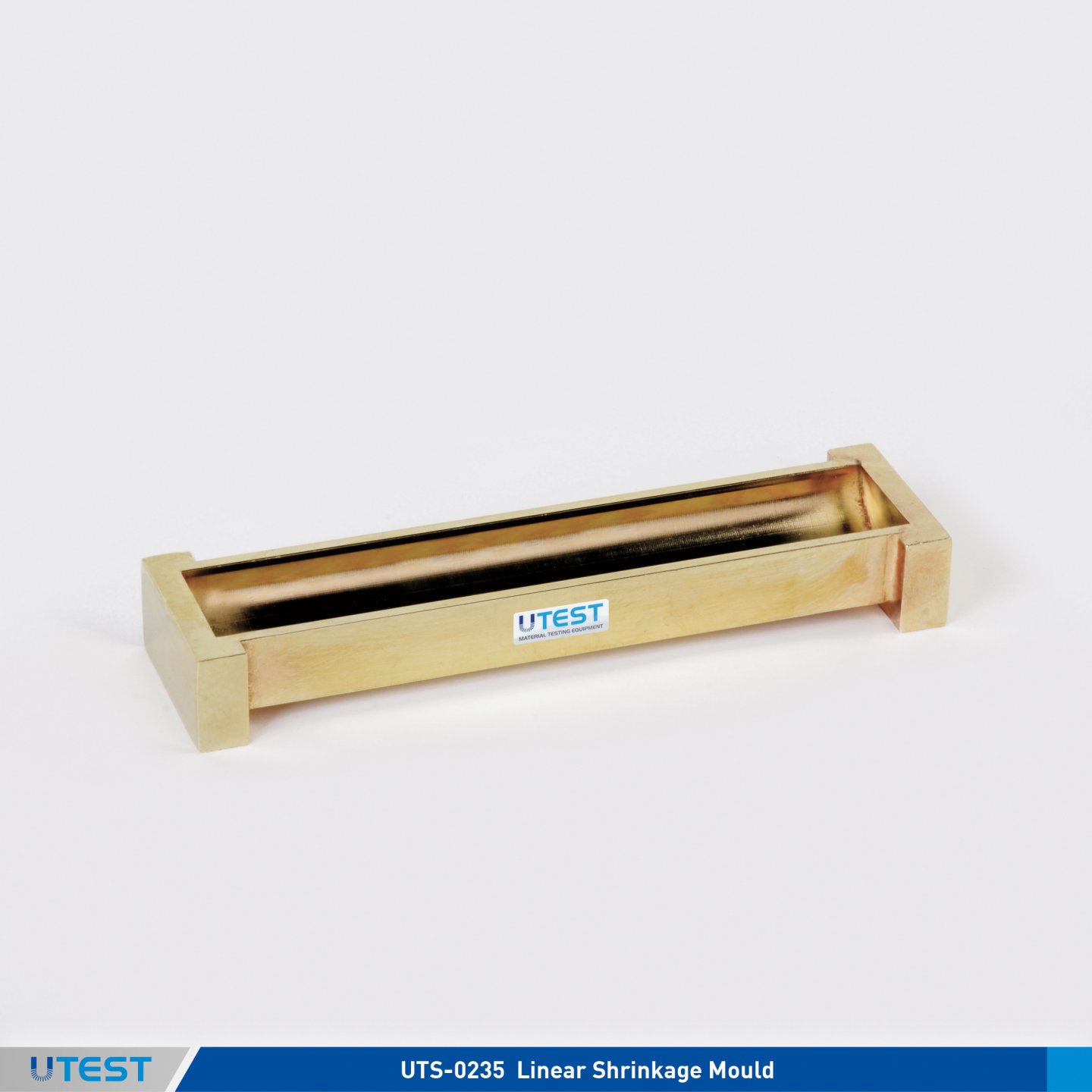
UTS-0235 |
Linear Shrinkage Mould |
Standards
BS 1377:2
The UTS-0235 Linear Shrinkage Mould is 140 mm long and 12.5 mm radius and is used for the determination of the total linear shrinkage of soils, and indicates the plastic properties of soils with low clay content.
|
Dimesions |
40x150x20 mm |
|
Weight (approx.) |
0,3 kg |
21. Sedimentation (Hydrometer) Test Set
Product Code
|
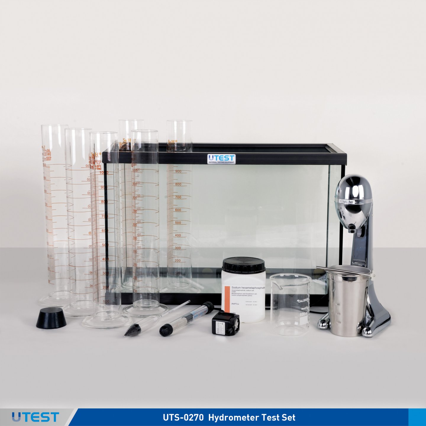
UTS-0270 |
Hydrometer Test Set |
|
UTS-0272E |
Soil Dispersion Mixer, 220-240 V 50-60 Hz, 1 ph |
|
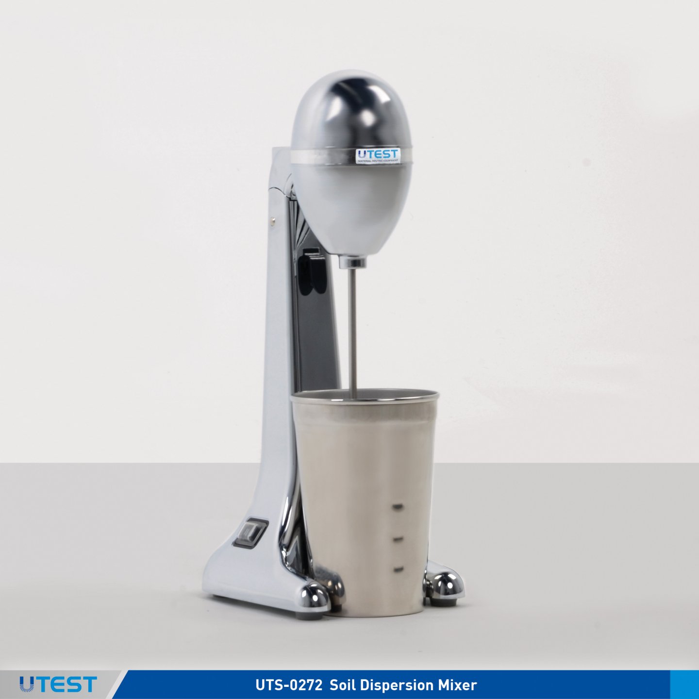
UTS-0272 |
Soil Dispersion Mixer, ASTM, AASHTO, EN 220-240 V 50-60 Hz, 1 ph |
|
UTS-0273 |
Hydrometer Bath, 220-240 V 50-60 Hz |
|
UTS-0274 |
Hydrometer 151H |
|
UTS-0275 |
Hydrometer 152H |
|
UTS-0276 |
Hydrometer Jar (Sedimentation Cylinder), 1000 ml |
|
UTGC-0900 |
Sodium Hexametaphosphate, 1 kg |
Standards
ASTM D7928; AASHTO T88; EN ISO 17892-4
Hydrometer Test Set is used to determine the particle size distribution of very fine materials such as silt and clay.
Soil dispersion mixer which are necessary for the test should be ordered separately.
50 L (8 cylinders) capacity hydrometer bath complete with a circulating unit, a heater (ambient to 35°C working temperatue) and a thermostate.
As an alternative of 151H hydrometer, 152H hydrometer can be available.
The soil dispersion mixers with baffle rods for hydrometer test include dispersion cup, stirring paddle, automatic switch-on by positioning bowl, 100 W power consumption.
|
151 H Hydrometer |
11" length |
0,995-1,038 g/ml |
in 0,001 g/ml division |
|
152 H Hydrometer |
11" length |
-5 - 60 g/L in 1g/L |
in 1g/L division |
The Hydrometer Test Set is supplied complete with;
- Hydrometer bath (with heater, circulation unit and thermostate)
- 151H Hydrometer or 152H Hydrometer (alternatively available ) (1 pcs)
- Hydrometer Jar (Sedimentation cylinder), 1000 ml (6 pcs) and rubber stopper(1 pcs)
- Beaker, 600 cc (1 pcs)
- Sodium hexametaphosphate 1 kg
|
Dimensions |
600x300x400 mm |
|
Weight (approx.) |
20 kg |
22. End - Over - End Shaker
Product Code
|
UTS-0170 |
Mechanical End-Over-End Shaker |
|
UTS-0171 |
Gas Jar with a Rubber Cover for UTS-0170 |
|
UTS-0172 |
Ground Glass. For UTS-0171 |
|
Models for 220-240V 50 Hz, 1 ph |
UTS-0170-T |
|
Models for 110-120V 60 Hz, 1 ph |
UTS-0170-N |
|
Models for 220-240V 60 Hz, 1 ph |
UTS-0170-K |
Standards
BS 1377:2, EN ISO 17892-4
The UTS-0170 Mechanical End-Over-End Shaker is used for the determination of the particle density by the gas jar method and the particle size distribution by sedimentation.
End-Over-End Shaker is used to rotate two gas jars with rubber covers at about 50 rpm.
The 1 L capacity gas jar is made of plexiglass.
UTS-0171 Gas Jar with a rubber cover and UTS-0172 ground glass should be ordered separately.
UTS-0172 and UTS-0171
|
Product Code |
Dimensions |
Weight (approx.) |
Power |
|
UTS-0170 |
500x1030x450 mm |
33 kg |
180 W |
|
UTS-0171 |
120x120x280 mm |
0,60 kg |
|
23. Indicator Papers pH Range
Product Code
|
UTGE-4300 |
pH Indicator Papers, pH Range 1 to 14 |
|
UTGE-4320 |
Quantab Chloride Titrator Type 1175, 40 strips/pack |
|
UTGE-4322 |
Quantab Chloride Titrator Type 1176, 40 strips/pack |
Standards
BS 812:117, 1377:3
The UTGE-4300 pH Indicator Papers are used for quick determination of pH in the 1 to 14 pH range.
UTGE-4320 and UTGE-4322 Quantab Chloride Titrators are used for quick determination of water soluble chloride salts present in soils and aggregates.
It is based on the Volhard Method. UTGE-4320 covers 0.005% to 0.1% NaCl and UTGE-4322 covers 0.05% to 1% NaCl.
|
Product Code |
Dimensions |
Weight (approx.) |
|
UTGE-4300 |
50x10x80 mm |
0.1 kg |
|
UTGE-4320 |
70x70x120 |
0.1 kg |
|
UTGE-4322 |
70x70x120 |
0.1 kg |
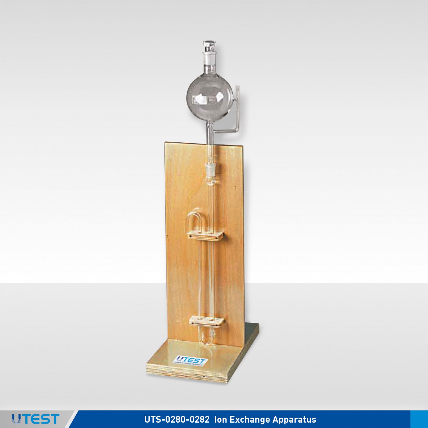
24. Ion Exchange Apparatus
Product Code
|
UTS-0280 |
Ion Exchange Apparatus |
|
UTS-0282 |
Ion Exchange Resin 500 g |
Standards
BS 1377:3
The UTS-0280 Ion Exchange Apparatus when used together with UTS-0282 Ion Exchange Resin, is used to determine the sulphate content of aqueous soil extracts and ground water.The apparatus consists of an ion exchange column of 10 mm diameter and 400 mm long, swan-neck outlet and a 1500 ml round bottom flask to give a constant head. The apparatus is supplied assembled on a stand.
UTS-0282 Ion Exchange Resin, 500 g should be ordered separately.
|
|
UTS-0280 |
UTS-0282 |
|
Dimensions |
200x100x600 mm |
50x50x50 mm |
|
Weight (approx.) |
5 kg |
0,50 kg |
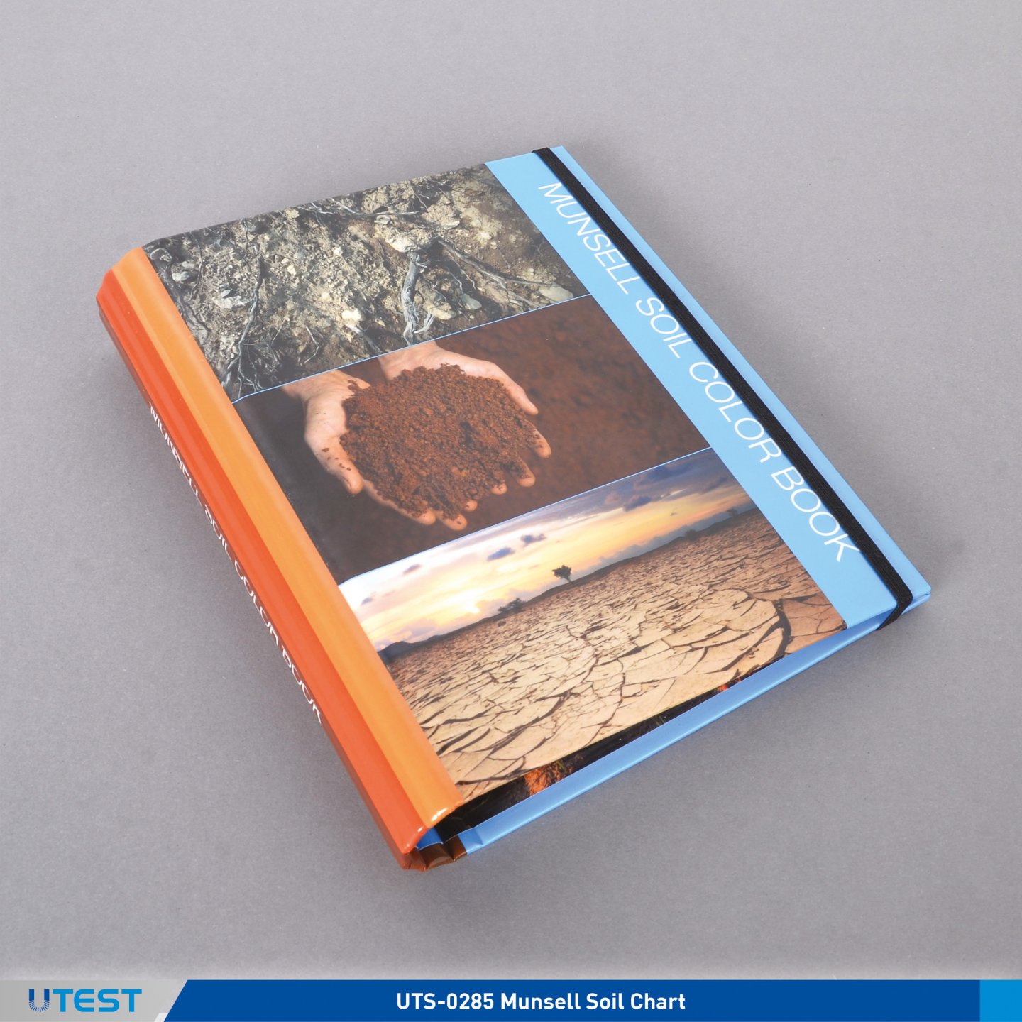
25. Munsell Soil Chart
Product Code
|
UTS-0285 |
Munsell Soil Chart |
The UTS-0285 Munsell Soil Chart provides a simple method for soil classification by of determining the color of soil specimens.
Test set consists of 7 constant hue charts covering a total of 196 colors.
The color chart and the diagram are fitted in a pocket size binder.
Supplied complete with a Tropical Soil Color Chart, set of 2 which can be fitted into the binder of UTS-0285.
|
Dimensions |
140x190x30 mm |
|
Weight (approx.) |
0,50 kg |
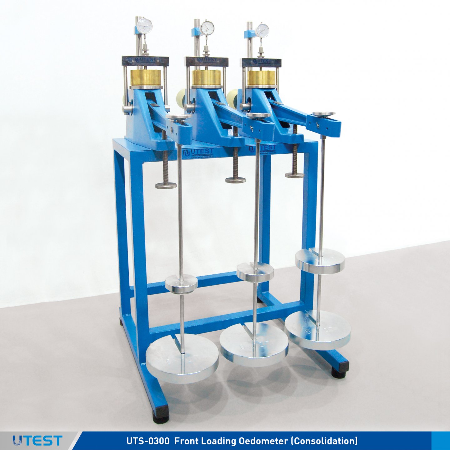
26. Consolidation
Product Code
|
UTS-0300 |
Front Loading Oedometer (Consolidation) |
|
UTS-0302 |
Bench for Consolidation, 3 Oedometer Capacity |
|
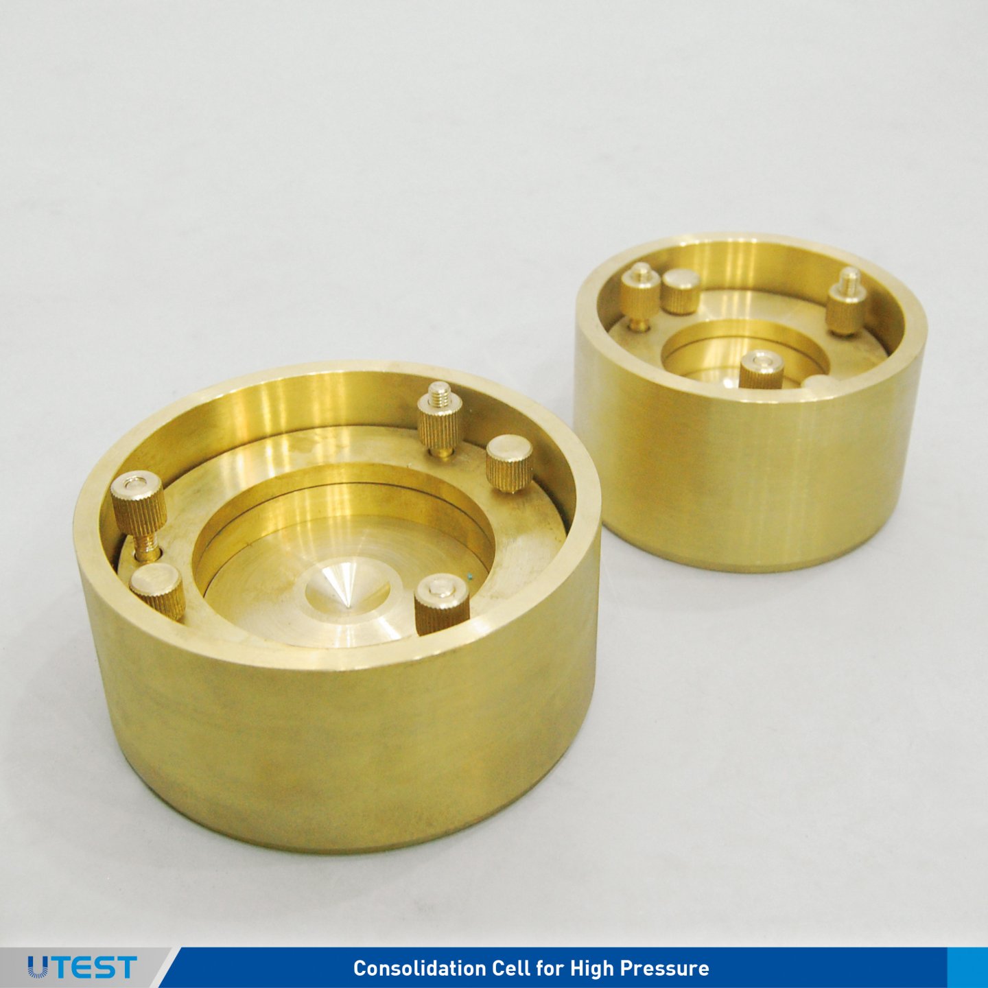
UTS-0307 |
Consolidation Cell for High Pressure, Ø 50 mm |
|
UTS-0309 |
Consolidation Cell for High Pressure, ASTM Ø 63.5 mm (2.5”) |
|
UTS-0313 |
Consolidation Cell for High Pressure, BS/EN, Ø 75 mm |
|
UTS-0315 |
Consolidation Cell for High Pressure, Ø 101,6 mm (4") |
|
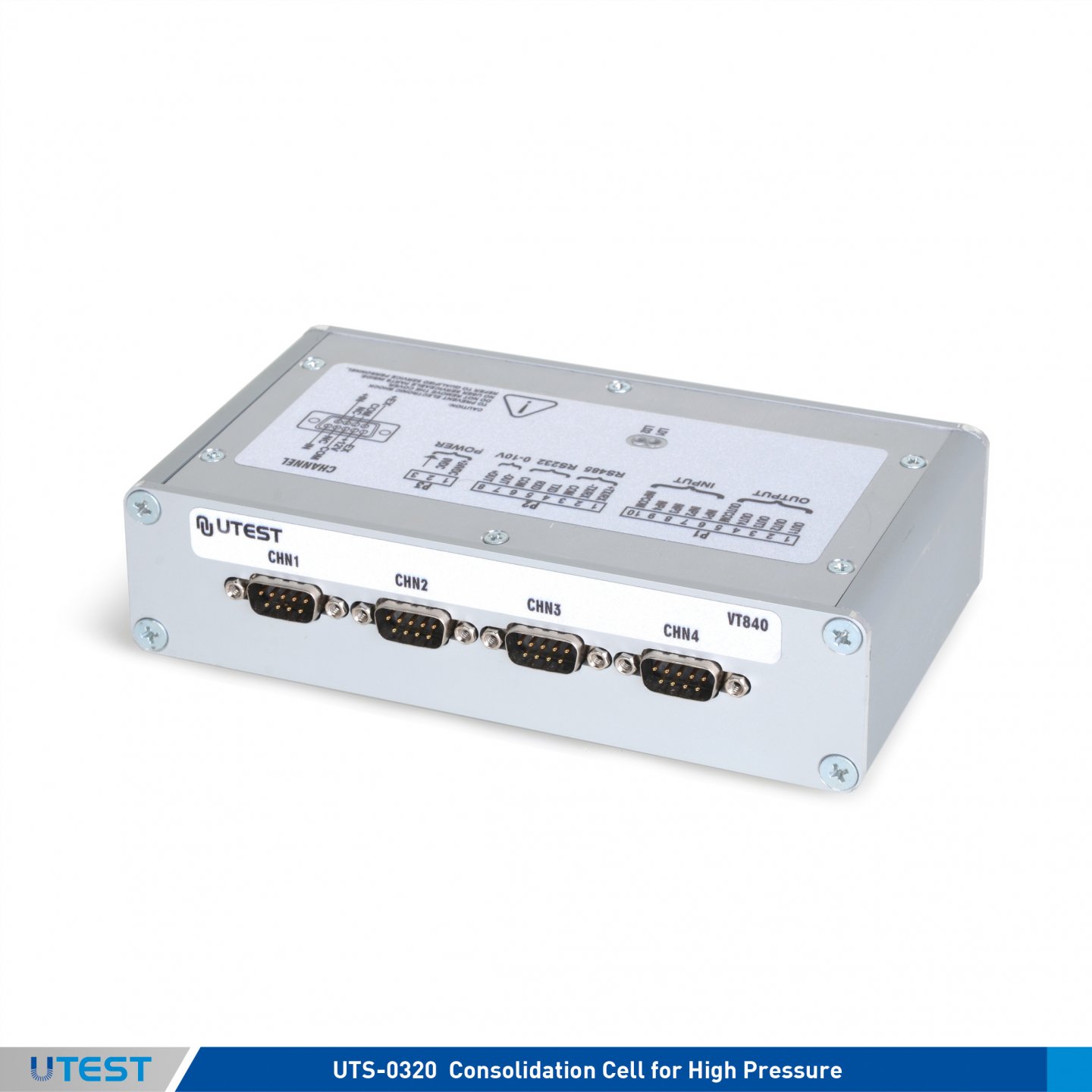
UTS-0320 |
Consolidation Cell for High Pressure, Ø112,8 mm |
|
UTGM-0120 |
Analog Dial Gauge, 30x0.01 mm |
|
UTGM-0148 |
Digital Dial Gauge 25x0.01 mm, LCD display |
|
UTGM-0152 |
Digital Dial Gauge 12.7x0.001 mm, LCD display |
|
UTGM-0060 |
Linear Potentiometric Displacement Transducer, 10x0,001mm |
|
UTGM-0062 |
Linear Potentiometric Displacement Transducer, 25x0,001mm |
|
UTGM-0072 |
High Accurate Strain Gauge Based Displacement Transducer, 10x0,001 mm |
|
UTGM-0078 |
High Accurate Strain Gauge Based Displacement Transducer, 50x0,001 mm |
|
UTCU-0020 |
Interface Unit with 4 Channel for Data Acquisition |
|
UTCU-0025 |
Interface Unit with 8 Channel for Data Acquisition |
|
UTS-0300 |
Utest Software for Consolidation Test |
Standards
BS 1377:5; ASTM D2435, D3877, D4546; AASHTO T216; EN ISO 17892-5
The UTS-0300 Front Loading Oedometer is rigidly constructed to ensure minimum frame distortion. The frame is designed to load the specimen through a lever arm assembly and one of three alternative beam ratios as 9:1, 10:1 and 11:1. The beam is fitted with a counter balance weight and beam support jack. The cell platform will accept the complete range UTEST consolidation cells and is fitted with a central spigot to ensure accurate centering of the cell under the loading.
The UTEST fixed ring consolidation cells are manufactured from corrosion-resistant materials and conform to the requirements of the relevant standards. An integral water reservoir is incorporated in the cell which allows the specimen to be inundated when required. All cells are supplied complete with upper and lower porous disc, pressure pad and cutting (specimen) ring.
The One-dimensional consolidation test is used to determine the consolidation characteristics of soils of low permeability.
Tests are carried out on specimens prepared from undisturbed samples. Data obtained from these tests together with classification data and a knowledge of the soils loading history, enables estimates to be made of the behavior of foundations under load. Consolidation cell, dial gauge or displacement transducer and data logger, bench, weights, apparatuses for prepare consolidation samples and calibration disc should be ordered separately.
UTS-0300, UTS-0302, UTS-0307 and UTGM-0120 UTS-0300, UTS-0302, UTS-0307 and UTGM-0148
Data Acquisition & PC Software
4 or 8 channel interface units for data acquistion (UTCU-0020 or UTCU-0025) are used for recording displacement data over time.
- High resolution : 260.000 points.
- Serial port for PC and printer connection.
- CPU card by microprocessor 32 bit ARM risk architecture.
- 4 or 8 analogical channels for displacement transducers.
Utest Consolidation Software (USOFT-0300) is developed according to ASTM D2435, D3877, D4546, BS 1377:5 and AASHTO T216 standards to be used with UTCU-0020 and UTCU-0025. Displacement transducers are connected to interface unit and interface unit is connected to PC by RS232 serial output. The software is capable monitoring the change of displacement data over time.
User can initiate and end data recording process by using the software. The user can determine and assign different time intervals (or select fixed time intervals) and stresses for the calculation of the consolidation test data.
The consolidation software has different data recording columns each assigned to the consolidation cells and they can be set to different normal load (stress) values. The user can also manually enter the vertical displacement data to these columns for correction. The graphs of time-displacement pairs are drawn in both square-root time and logarithmic time scales. In addition to these visualizations, the software can calculate required parameters such as √t90, √t50, √t100, mv, Cv , etc. according to the related standards indicated above. Recorded data, graphs, calculations and all other generic data can be exported to Microsoft Excel for further evaluation.
- Customizable User Interface
- Graphical outputs and reports can be saved as MS Excel worksheet
- Flexibility in edit report and graph templates
UTCU-0020
|
Dimensions |
750x850x1400 mm (3 pcs UTS-0300 + UTS-0302 + UTS-0376 + Accessories) |
|
Weight (approx.) |
180 kg (3 pcs UTS-0300 + UTS-0302 + UTS-0376 + Accessories) |
|
P. Name |
UTS-0307 (Ø50 mm) |
UTS-0309 Ø63,5 mm (2,5") |
UTS-0313 (Ø75 mm) |
UTS-0315 Ø101,6 mm (4") |
UTS-0320 Ø112,8 mm |
|
Spare Cutting Ring |
UTS-0308 |
UTS-0312 |
UTS-0314 |
UTS-0318 |
UTS-0322 |
|
Upper and Lower Porous Disc |
UTS-0330 |
UTS-0331 |
UTS-0333 |
UTS-0335 |
UTS-0338 |
|
Calibration Disc, stainless steel |
UTS-0339 |
UTS-0341 |
UTS-0343 |
UTS-0345 |
UTS-0347 |
|
Apparatus for Prepare Consolidation Sample |
UTS-0358 |
UTS-0359 |
UTS-0360 |
UTS-0362 |
UTS-0364 |
|
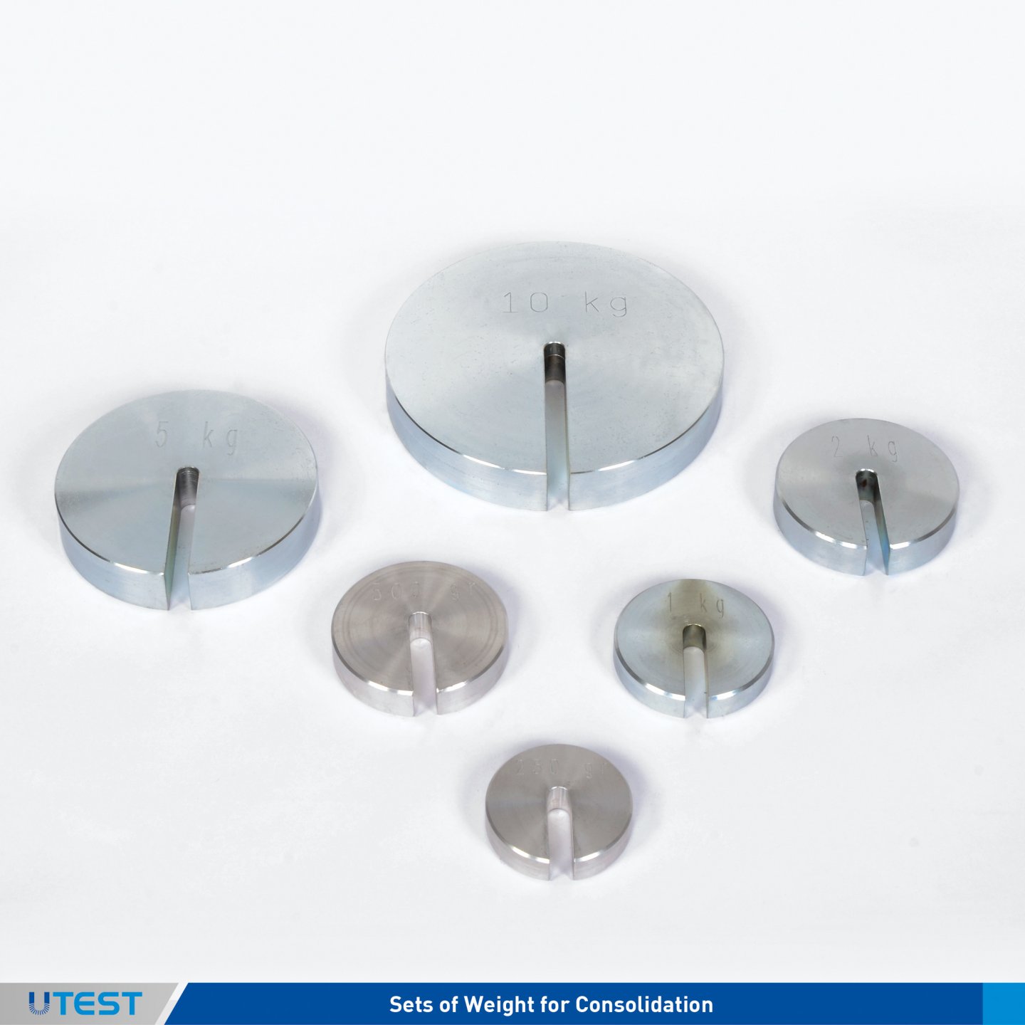
P. Code |
Sets of Weight for Consolidation |
|
|
UTS-0368 |
16 kgf Set |
(2) 5 kg, (1) 2 kg, (2) 1 kg, (3) 0,5 kg, (2) 0,25 kg |
|
UTS-0370 |
32 kgf Set |
(1) 10 kg, (3) 5 kg, (2) 2 kg, (1) 1 kg, (3) 0,5 kg, (2) 0,25 kg |
|
UTS-0372 |
50 kgf Set |
(3) 10 kg, (2) 5 kg, (3) 2 kg, (2) 1 kg, (3) 0,5 kg, (2) 0,25 kg |
|
UTS-0374 |
64 kgf Set |
(4) 10 kg, (3) 5 kg, (2) 2 kg, (3) 1 kg, (3) 0,5 kg, (2) 0,25 kg |
|
UTS-0376 |
80 kgf Set |
(6) 10 kg, (2) 5 kg, (3) 2 kg, (2) 1 kg, (3) 0,5 kg, (2) 0,25 kg |
|
P. Code |
Slotted Weight |
|
|
UTS-0380 |
125 g |
|
|
UTS-0382 |
250 g |
|
|
UTS-0384 |
500 g |
|
|
UTS-0386 |
1 kg |
|
|
UTS-0388 |
2 kg |
|
|
UTS-0390 |
5 kg |
|
|
UTS-0392 |
10 kg |
|
|
UTS-0394 |
4 kg |
|
|
UTS-0396 |
8 kg |
27. Automatic Direct / Residual Shear Test Machine
Product Code
|
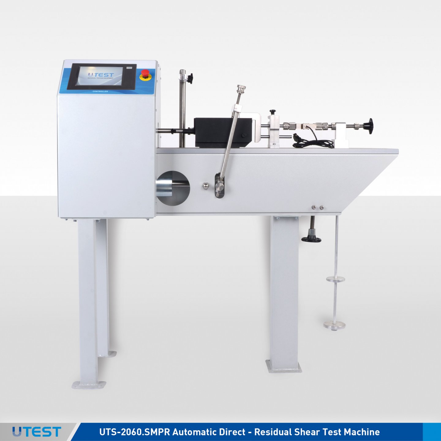
UTS-2060.SMPR |
Automatic Direct - Residual Shear Test Machine |
|
UTS-2065 |
Shear Box Assembly, 60x60 mm |
|
UTS-2065-07 |
Cutting Ring, 60x60 mm |
|
UTS-2065-08 |
Extrusion Dolly, 60x60 mm |
|
UTS-2065-09 |
Calibration Disk for UTS-2065 |
|
UTS-2066 |
Shear Box Assembly, Ø 60 mm |
|
UTS-2066-07 |
Cutting Ring, Ø 60 mm |
|
UTS-2066-08 |
Extrusion Dolly, Ø 60 mm |
|
UTS-2066-09 |
Calibration Disk for UTS-2066 |
|
UTS-2067 |
Shear Box Assembly, 100x100 mm |
|
UTS-2067-07 |
Cutting Ring, 100x100 mm |
|
UTS-2067-08 |
Extrusion Dolly, 100x100 mm |
|
UTS-2067-09 |
Calibration Disk for UTS-2067 |
|
UTS-2068 |
Shear Box Assembly, Ø 100 mm |
|
UTS-2068-07 |
Cutting Ring, Ø 100 mm |
|
UTS-2068-08 |
Extrusion Dolly, Ø 100 mm |
|
UTS-2068-09 |
Calibration Disk for UTS-2068 |
|
UTS-2069 |
Shear Box Assembly, Ø 2.5 inch |
|
UTS-2069-07 |
Cutting Ring, Ø 2.5 inch |
|
UTS-2069-08 |
Extrusion Dolly, Ø 2.5 inch |
|
UTS-2069-09 |
Calibration Disk for UTS-2069 |
|
UTS-2100 |
Slotted Weight Set, 50 kg (4x10 kg + 1x5 kg + 1x2 kg + 3x1 kg) |
|
Models for 220-240V 50-60 Hz, 1 ph. |
UTS-2060.SMPR |
|
Models for 110-120V, 60Hz, 1ph. |
UTS-2060.SMPR -N |
Standards
ASTM D3080; BS 1377:7; AASHTO T236, TS 1900-2, EN-ISO 17892-10
The test covers the determination of consolidated drained shear strength of a soil material by direct shear. UTS-2060.SMPR Automatic Direct - Residual Shear Test Machine is motorized and floor mounted. Normal stress is applied to the specimen by utilizing a weight hanger, a lever arm (amplification ratios of 9:1, 10:1 and 11:1), and a vertical loading yoke. Hanger can receive up to 50 kg of weight which is amplified by the lever arm and transferred to the specimen by the vertical loading yoke as a normal force up to 5 kN (5000 N).
The machine is supplied with a shearbox bowl that accepts 60 mm square, 100 mm square, 60 mm dia. round, 100 mm dia. round and 2.5 inc. dia. round shearboxes. Shearbox bowl is designed to contain water to inundate the specimen during the test. The shearbox assemblies consist of rigid walled shear box, a vertical loading pad with grooved back face, a grooved retaining plate and 2pcs. porous plates (UTS-2067-04).
Drive unit utilizes a high resolution servomotor and a gear box assembly to ensure continuously variable transmission of speed in a range from 0.00001 mm-min. to 15 mm-min for both forward and reverse directions. 5 kN load cell is used for load measurement. 10 x 0.001 mm and 25 x 0.001 mm sensitivity linear potentiometric transducers are used for vertical and horizontal displacement measurements respectively. Displacement limits are controlled by limit switch.
Shearbox Assemblies, Slotted Weight Sets or Individual Weights and other optional accessories including cutting ring and extrusion dolly should be ordered separately.
|
Accessories of Shear Box Assemblies |
|||||
|
The Model of Shear Box |
UTS-2065 60x60 mm |
UTS-2066 Ø:60 mm |
UTS-2067 100x100 |
UTS-2068 Ø:100 mm |
UTS-2069 Ø:2,5 inch |
|
Shear Box |
UTS-2065-01 |
UTS-2066-01 |
UTS-2067-01 |
UTS-2068-01 |
UTS-2069-01 |
|
Loading Cap |
UTS-2065-02 |
UTS-2066-02 |
UTS-2067-02 |
UTS-2068-02 |
UTS-2069-02 |
|
Grooved Retaining Plate |
UTS-2065-03 |
UTS-2066-03 |
UTS-2067-03 |
UTS-2068-03 |
UTS-2069-03 |
|
Porous Plates (2 pcs.) |
UTS-2065-04 |
UTS-2066-04 |
UTS-2067-04 |
UTS-2068-04 |
UTS-2069-04 |
|
The OPTIONAL Accessories of UTS-2060 Automatic Direct / Residual Shear Test Machine |
|||||
|
Specimen Cutter |
UTS-2065-07 |
UTS-2066-07 |
UTS-2067-07 |
UTS-2068-07 |
UTS-2069-07 |
|
Extrusion Dolly |
UTS-2065-08 |
UTS-2066-08 |
UTS-2067-08 |
UTS-2068-08 |
UTS-2069-08 |
|
Calibration Disk |
UTS-2065-09 |
UTS-2066-09 |
UTS-2067-09 |
UTS-2068-09 |
UTS-2069-09 |
UTS-2069-08
UTS-2065-8
|
Alternative Slotted Weight Sets of UTS-2100 |
|
Individual Slootted Weights |
|||||||
|
Product Codes |
Total Mass |
Included weight |
|||||||
|
1 kg |
4 kg |
8 kg |
UTS-0382 |
0,25 kg |
UTS-0390 |
5 kg |
|||
|
UTS-2102 |
32 kg |
4 |
3 |
2 |
UTS-0384 |
0,50 kg |
UTS-0392 |
10 kg |
|
|
UTS-2104 |
64 kg |
4 |
5 |
5 |
UTS-0386 |
1 kg |
UTS-0394 |
4 kg |
|
|
UTS-2106 |
88 kg |
4 |
5 |
8 |
UTS-0388 |
2 kg |
UTS-0396 |
8 kg |
|
U-Touch PRO Control Unit for Direct/Residual Shear Test
The U-Touch PRO Control Unit for Direct/Residual Shear Test is designed to control the machine to perform direct - residual shear test acc. to EN,ASTM/AASHTO and BS standards to process.
The Unit can perform direct - residual shear tests as a stand-alone without the use of a PC or with the USOFT-2060 software and a PC. Control of machine, acquisition of load and displacement data in real time are provided by the unit
The U-Touch PRO has easy to use menu options. It displays all menu option listings simultaneously, allowing the operator to access the required option quickly to activate that option or enter a numeric value to set the test parameters and see all the data while the test running.
The U-Touch PRO graphic display allows real time Load etc. Displacement or Stress etc. Displacement graph. The advanced functions for data base management provide an easy navigation of all saved data. The test results certificate includes all descriptive information. Therefore test parameters can be set and details about the test carried out such as customer details, test type, specimen type, user info and other information required can be entered and printed out as well as test reports and graphs. Also, all minor revisions can be implemented upon request. The Software calculates both the maximum and resilient shear stress.
After three runs, the software calculates the cohesion value “c” and shear resistance angle”φ” by using the best straight line fit.
Main Features
• Can make the test with displacement control.
• Real time display of test graph.
• 4 analog channels for load cell and displacement sensor
• Calibration function for channels.
• Programmable digital gain adjustment for load-cell and potentiometric sensors, voltage and current transmitters.
• Closed-loop PID for steady pace rate.
Consolidation
• 25 pairs of time-vertical displacement values are written to memory.
• The vertical displacement value can be tared prior to recording.
• The analogical channel reading vertical displacement has 260000 points effective resolution.
• The memory can be exported to PC software.
Testing
• 3 different shearing test types can be selected.
• The machine run with the speed determined by user to the direction of shear and stop when the load decreases.
• The machine run with the speed determined by user to the direction of shear and stop when it reaches to the target horizontal displacement value which is also determined by the user at the beginnig of the test.
• The machine run with the speed to the direction of shear, after reaching to the target displacement, returns and finds the exact initial (HOME) position, waits for the dissipation of excess pore pressure and starts to the same procedure again. User can create testing scenarios by determining all the parameters of this multi-reversal shearing test such as test speed, return speed, displacement target, standby time, and cycle number.
• By using the control unit, consolidation before shearing tests are possible.
• The screen displays load, shear stress, horizontal and vertical displacements, and τ-Δx graph continuously.
PLEASE see the pages of “General Properties of U-Touch PRO Control Units” for details of the properties of software and hardware.
USOFT-2060 UTEST Software for Direct/Residual Shear Test
Utest Direct and Residual Shear Software is developed in accordance with ASTM D3080, BS 1377:7 and AASHTO T 236 standards to be used with UTS-2060.SMPR Machine.
Direct residual and shear software consist of two sections. First section is used for the consolidation of the sample prior to shear.
The second section of the software is capable of performing three different types of test. The first type moves the machine with the speed determined by user until a shear failure occurs. On the second type, the user can set a speed and a horizontal displacement and the test will continue until the machine reaches to the set value.
On the last type of test, the machine can be configured for cyclic (multireversal) operation. In cyclic mode device will advance to the determined distance with an assigned speed and turn back to the initial (home) position with a different assigned speed, wait for a time for the dissipation of excess pore pressure and start to the new cycle again.
All these test parameters such as forward-reverse speed, distance, cycle number, etc. can be defined by the user.
The software supports 5 different normal load values in order to calculate cohesion (C) and internal friction angle (Ø) values. Prior to the test normal load value must be entered to the software.
The normal stress is calculated according to normal load and sample size automatically.
The software supports both square and round type samples.
Stress values can be optionally and automatically calculated as “standard area” and the “corrected area” approach. When the test is completed peak and residual stress values are recorded.
The normal load versus peak stress pair is used for the calculation of cohesion and internal friction angle value. At least 3 loading with different normal loads are required for this property.
One can set test speed, axis values etc. through the setup of the software. The results can be submitted as a report or can be exported to Microsoft Excel for advanced reanalyze procedures.
See the pages of “General Properties of Utest USOFT Softwares” for detailed properties of the software.
The Automatic Direct Residual Shear Test Machine is supplied complete with;
- Load Cell 5 kN
- Linear Potentiometric Displacement Transducer (10x0.001 mm)
- Linear Potentiometric Displacement Transducer (25x0.001 mm)
- Software
|
Speed Range |
0.00001 to 10,00 mm/min |
|
Maximum Shear Force |
5 kN (5000 N) |
|
Maximum Vertical Load |
0 to 500 N |
|
Horizontal Travel |
30 mm |
|
Dimensions |
450x1250x1200 mm |
|
Weight (approx.) |
110 kg |
|
Power |
1100 W |
28. Triaxial UU-CU-CD Test Systems
Product Code
Triaxial Test Systems
Standards
ASTM D2850, D4767, D7181; AASHTO T-297; BS 1377-7, BS 1377-8
Determining the mechanical properties of soils is a very important step to design foundations, embankments and other soil structures. Building constructions, excavations, tunnelling and similar applications have several effects on the subsoil structures and these effects are successfully simulated with Triaxial Tests where the stress-strain relation of undisturbed soil specimen are investigated by subjecting the soil sample to different stress levels and drainage conditions.
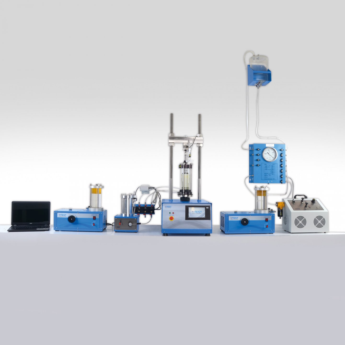
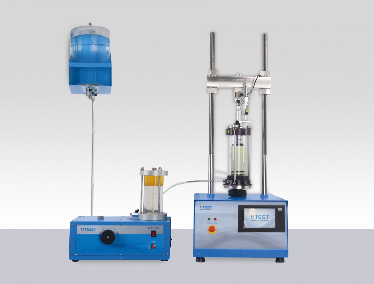
The UTEST Triaxial Test System provides automated triaxial compression tests on cylindrical undisturbed and remolded soil samples. Unconsolidated undrained (UU), consolidated drained (CD) and consolidated undrained (CU) compression tests can be automatically run, controlled and reported using this apparatus.
Unconsolidated Undrained (UU) Test
For the UU test, the specimens (assumed to be saturated prior to test) are subjected to a confining fluid pressure in a triaxial chamber. Once the specimen is inside the triaxial cell, the cell pressure is increased to a predetermined value by rotating the knob of the constant pressure unit, and the specimen is brought to failure by increasing the vertical stress by applying a constant rate of axial strain. Since saturation and consolidation do not exist in this method, original structure and water content of sample is untouched. Pore and back pressures are not measured during this test and therefore the results can only be interpreted in terms of total stress over a confinement pressure (stress).
These tests are generally carried out on three specimens of the same sample subjected to different confining stresses.
Since all specimens are supposedly saturated the shear strength are similar for all tests.
The results of the test are plotted as curves of principal stres difference against strain. For conditions of maximum principal stress difference (taken as failure) Mohr circles are plotted in terms of total stress. The average undrained shear strength is recorded, and the failure (Mohr) envelope is drawn tangential to the Mohr circles in order to find the “undrained cohesion intercept” and undrained “angle of shearing resistance”.
Consolidated Undrained (CU) Test & Consolidated Drained (CD) Test
Peak effective strength parameters (c' and φ') can be determined either from the results of consolidated undrained (CU) triaxial compression tests with pore pressure measurement or from consolidated drained (CD) triaxial compression tests. The consolidated undrained/ drained triaxial compression tests are normally performed in several stages, involving the successive saturation, consolidation and shearing of each of three specimens.
Saturation is carried out in order to ensure that the pore fluid in the specimen does not contain free air. Saturation is normally carried out by leaving the specimens to an elevated back pressure so that the air in the pores is dissolved in water. Back pressure (which is simply an imposed pore pressure) is applied through a volume change gauge to the top of the specimen, while a cell pressure of slightly higher value is also applied. Both cell pressure and back pressure are normally increased in increments, allowing time for equalization at each stage. The degree of saturation can be expressed in terms of Skempton's pore pressure parameter (Skempton, 1954):
Δ u
B=__________
Δ σ3
Where Δu is equal to change in pore pressure for an applied cell pressure change of Δ σ3. For an ideally saturated soil B is equal to 1. It is recommended by several standard test methods that a value of B greater than, or equal to, 0.95 must be achieved before the specimen may be considered as fully saturated and the consolidation stage started.
The consolidation stage of an effective stress triaxial test is carried out for two reasons. First, three specimens are tested and consolidated at three different effective pressures, in order to give specimens of different strengths which will produce widely spaced effective stress Mohr circles. Secondly, the results of consolidation are used to determine the minimum time to failure in the shear stage.
The effective consolidation pressures (i.e. cell pressure minus back pressure) will normally be increased by a factor of two between each specimen, with the middle pressure approximating to the vertical effective stress in the ground. When the consolidation cell pressure and back pressure are applied to the specimen, readings of volume change are made using a volume change device in the back pressure line. Pore pressure is measured at the specimen base, with drainage to the back pressure line taking place through a porous stone covering the top of the specimen.
The coefficient of consolidation of the clay can be determined by plotting volume change as a function of the square root of time. Theoretical considerations indicate that the first 50% of volume loss during consolidation should show as a straight line on this plot. This straight line is extended down to cut the horizontal line representing 100% consolidation, and the time intercept at this point (termed “t ” by Bishop and Henkel) 100 can be used to obtain the coefficient of consolidation.
Consolidated Undrained (CU) Test:
Once consolidation is complete, the specimen is to be isolated from the back pressure and the rate of vertical movement of the compression machine platen set according to result of consolidation. During the shear stage the vertical stress is increased by the loading ram and measurements are made at regular intervals of deformation, ram load and pore pressure. These are converted to graphs of principal stress difference (σ1- σ3) and pore pressure as a function of strain, and failure is normally taken as the point of maximum principal stress difference. The effective stress Mohr circles are plotted for the failure conditions of the three specimens which has been subjected to different consolidation level, and the gradient and intercept of a straight line drawn tangential to these circles defines the effective strength parameters c' and φ'.
Consolidated Drained (CD) Test:
The consolidated drained triaxial compression test, with volume change measurement during shear is carried out in a similar sequence to the consolidated undrained test, but during shear the back pressure remains connected to the specimen which is loaded sufficiently slowly to avoid the development of excess pore pressures.
The shear stage of a drained triaxial test can be expected to take between 7 and 15 times longer than that of an undrained test with pore pressure measurement.
Once shearing is complete, the results are presented as graphs of principal stress difference and volume change as a function of strain, and the failure Mohr circles are plotted to give the drained failure envelope defined by the parameters cd' and φd' .
Triaxial CD-CU-UU equipment is computer controlled, test values can be transferred to computer and data processing can be made with Triaxial software on Windows operating system. All data can be used on Excel programs.
The load data and axial displacement data are transfered and recorded through UTouch Control Unit to the software.
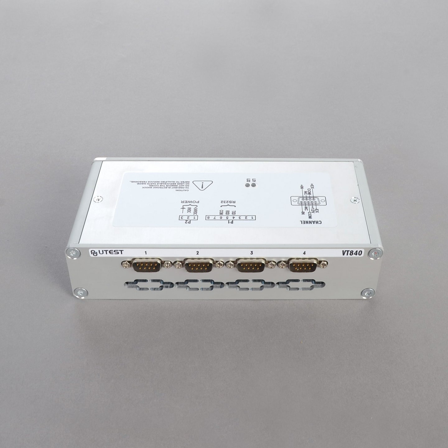
Three pressure data (cell pressure, back pressure and pore pressure) from triaxial cell and volume change data transfered and recorded through the interface unit with 4 channel for data acquisition (UTCU-0020) to the software.
|
Typical Configuration of System for Triaxial Tests ( UU-CU-CD) |
|||
|
Product Code |
Description |
UU |
UU-CU-CD |
|
UTM-0108.SMPR |
Multiplex Universal Electromechanic Test Machine* |
1 |
1 |
|
UTGM-1180 |
Load Cell 5 k N, S Type |
1 |
1 |
|
UTGM-1190 |
Load Cell 10 kN, Pancake Type** |
1 |
1 |
|
UTS-2400 |
Triaxial Cell*** |
1 |
1 |
|
UTS-2401 |
Triaxial Cell*** |
1 |
1 |
|
UTS-2406 |
Block with one connection line and pressure transducer |
1 |
3 |
|
UTS-2408 |
Oil and Water Constant Pressure System |
1 |
2 |
|
UTS-2415 |
Automatic Volume Change Unit |
- |
1 |
|
UTCU-0020 |
Interface Unit with 4 Channel for Data Acquisition |
- |
1 |
|
USOFT-2419 |
Software to Perform UU Triaxial Tests |
1 |
1 |
|
USOFT-2420 |
Software to Perform CU-CD Triaxial Tests |
- |
1 |
|
UTS-1330 |
De-Airing Water Tank, 7 L. |
1 |
1 |
|
UTGP-1145 |
Plastic Hose, Ø8mm OD, 10 m |
1 |
1 |
* Has a 50 kN frame and supplied complete with 50 mm linear potentiometric transducer (UTGM-0064) with holders (UTM-0114 and UTAS-1060) and a lower compression platen.Load cell and other test equipment should be ordered separately.
** May be need for 70-100 mm dia. samples with high strength.
*** Choose the suitable cell for the specimen size (UTS-2400: 38-50 mm dia. samples / UTS-2401: 70-100 mm dia. samples). For cell and cell accessories see “Triaxial Cells, Cell Accesories and Sample Preparation” page.
Optional Apparatus which should be ordered seperately for de-airing water see the page of De-Airing Water Systems”.
29. Triaxial UU-CU-CD Test Systems
Product Code
Triaxial Test Systems
Standards
ASTM D2850, D4767, D7181; AASHTO T-297; BS 1377-7, BS 1377-8
Determining the mechanical properties of soils is a very important step to design foundations, embankments and other soil structures. Building constructions, excavations, tunnelling and similar applications have several effects on the subsoil structures and these effects are successfully simulated with Triaxial Tests where the stress-strain relation of undisturbed soil specimen are investigated by subjecting the soil sample to different stress levels and drainage conditions.
The UTEST Triaxial Test System provides automated triaxial compression tests on cylindrical undisturbed and remolded soil samples. Unconsolidated undrained (UU), consolidated drained (CD) and consolidated undrained (CU) compression tests can be automatically run, controlled and reported using this apparatus.
Unconsolidated Undrained (UU) Test
For the UU test, the specimens (assumed to be saturated prior to test) are subjected to a confining fluid pressure in a triaxial chamber. Once the specimen is inside the triaxial cell, the cell pressure is increased to a predetermined value by rotating the knob of the constant pressure unit, and the specimen is brought to failure by increasing the vertical stress by applying a constant rate of axial strain. Since saturation and consolidation do not exist in this method, original structure and water content of sample is untouched. Pore and back pressures are not measured during this test and therefore the results can only be interpreted in terms of total stress over a confinement pressure (stress).
These tests are generally carried out on three specimens of the same sample subjected to different confining stresses.
Since all specimens are supposedly saturated the shear strength are similar for all tests.
The results of the test are plotted as curves of principal stres difference against strain. For conditions of maximum principal stress difference (taken as failure) Mohr circles are plotted in terms of total stress. The average undrained shear strength is recorded, and the failure (Mohr) envelope is drawn tangential to the Mohr circles in order to find the “undrained cohesion intercept” and undrained “angle of shearing resistance”.
Consolidated Undrained (CU) Test & Consolidated Drained (CD) Test
Peak effective strength parameters (c' and φ') can be determined either from the results of consolidated undrained (CU) triaxial compression tests with pore pressure measurement or from consolidated drained (CD) triaxial compression tests. The consolidated undrained/ drained triaxial compression tests are normally performed in several stages, involving the successive saturation, consolidation and shearing of each of three specimens.
Saturation is carried out in order to ensure that the pore fluid in the specimen does not contain free air. Saturation is normally carried out by leaving the specimens to an elevated back pressure so that the air in the pores is dissolved in water. Back pressure (which is simply an imposed pore pressure) is applied through a volume change gauge to the top of the specimen, while a cell pressure of slightly higher value is also applied. Both cell pressure and back pressure are normally increased in increments, allowing time for equalization at each stage. The degree of saturation can be expressed in terms of Skempton's pore pressure parameter (Skempton, 1954):
Δ u
B=__________
Δ σ3
Where Δu is equal to change in pore pressure for an applied cell pressure change of Δ σ3. For an ideally saturated soil B is equal to 1. It is recommended by several standard test methods that a value of B greater than, or equal to, 0.95 must be achieved before the specimen may be considered as fully saturated and the consolidation stage started.
The consolidation stage of an effective stress triaxial test is carried out for two reasons. First, three specimens are tested and consolidated at three different effective pressures, in order to give specimens of different strengths which will produce widely spaced effective stress Mohr circles. Secondly, the results of consolidation are used to determine the minimum time to failure in the shear stage.
The effective consolidation pressures (i.e. cell pressure minus back pressure) will normally be increased by a factor of two between each specimen, with the middle pressure approximating to the vertical effective stress in the ground. When the consolidation cell pressure and back pressure are applied to the specimen, readings of volume change are made using a volume change device in the back pressure line. Pore pressure is measured at the specimen base, with drainage to the back pressure line taking place through a porous stone covering the top of the specimen.
The coefficient of consolidation of the clay can be determined by plotting volume change as a function of the square root of time. Theoretical considerations indicate that the first 50% of volume loss during consolidation should show as a straight line on this plot. This straight line is extended down to cut the horizontal line representing 100% consolidation, and the time intercept at this point (termed “t ” by Bishop and Henkel) 100 can be used to obtain the coefficient of consolidation.
Consolidated Undrained (CU) Test:
Once consolidation is complete, the specimen is to be isolated from the back pressure and the rate of vertical movement of the compression machine platen set according to result of consolidation. During the shear stage the vertical stress is increased by the loading ram and measurements are made at regular intervals of deformation, ram load and pore pressure. These are converted to graphs of principal stress difference (σ1- σ3) and pore pressure as a function of strain, and failure is normally taken as the point of maximum principal stress difference. The effective stress Mohr circles are plotted for the failure conditions of the three specimens which has been subjected to different consolidation level, and the gradient and intercept of a straight line drawn tangential to these circles defines the effective strength parameters c' and φ'.
Consolidated Drained (CD) Test:
The consolidated drained triaxial compression test, with volume change measurement during shear is carried out in a similar sequence to the consolidated undrained test, but during shear the back pressure remains connected to the specimen which is loaded sufficiently slowly to avoid the development of excess pore pressures.
The shear stage of a drained triaxial test can be expected to take between 7 and 15 times longer than that of an undrained test with pore pressure measurement.
Once shearing is complete, the results are presented as graphs of principal stress difference and volume change as a function of strain, and the failure Mohr circles are plotted to give the drained failure envelope defined by the parameters cd' and φd' .
Triaxial CD-CU-UU equipment is computer controlled, test values can be transferred to computer and data processing can be made with Triaxial software on Windows operating system. All data can be used on Excel programs.
The load data and axial displacement data are transfered and recorded through UTouch Control Unit to the software.
Three pressure data (cell pressure, back pressure and pore pressure) from triaxial cell and volume change data transfered and recorded through the interface unit with 4 channel for data acquisition (UTCU-0020) to the software.
|
Typical Configuration of System for Triaxial Tests ( UU-CU-CD) |
|||
|
Product Code |
Description |
UU |
UU-CU-CD |
|
UTM-0108.SMPR |
Multiplex Universal Electromechanic Test Machine* |
1 |
1 |
|
UTGM-1180 |
Load Cell 5 k N, S Type |
1 |
1 |
|
UTGM-1190 |
Load Cell 10 kN, Pancake Type** |
1 |
1 |
|
UTS-2400 |
Triaxial Cell*** |
1 |
1 |
|
UTS-2401 |
Triaxial Cell*** |
1 |
1 |
|
UTS-2406 |
Block with one connection line and pressure transducer |
1 |
3 |
|
UTS-2408 |
Oil and Water Constant Pressure System |
1 |
2 |
|
UTS-2415 |
Automatic Volume Change Unit |
- |
1 |
|
UTCU-0020 |
Interface Unit with 4 Channel for Data Acquisition |
- |
1 |
|
USOFT-2419 |
Software to Perform UU Triaxial Tests |
1 |
1 |
|
USOFT-2420 |
Software to Perform CU-CD Triaxial Tests |
- |
1 |
|
UTS-1330 |
De-Airing Water Tank, 7 L. |
1 |
1 |
|
UTGP-1145 |
Plastic Hose, Ø8mm OD, 10 m |
1 |
1 |
* Has a 50 kN frame and supplied complete with 50 mm linear potentiometric transducer (UTGM-0064) with holders (UTM-0114 and UTAS-1060) and a lower compression platen.Load cell and other test equipment should be ordered separately.
** May be need for 70-100 mm dia. samples with high strength.
*** Choose the suitable cell for the specimen size (UTS-2400: 38-50 mm dia. samples / UTS-2401: 70-100 mm dia. samples). For cell and cell accessories see “Triaxial Cells, Cell Accesories and Sample Preparation” page.
Optional Apparatus which should be ordered seperately for de-airing water see the page of De-Airing Water Systems”.
30. Soil Triaxial Test Softwares
The CU-CD triaxial test is a complicated test needs load data, diplacement data 3 pressure data from triaxial cell and volume change data. Load data and displacement data are transfered and recorded through UTouch Control Unit to the software. 3 pressure data from triaxial cell and volume change data transfered and recorded through the interface unit with 4 channel for data acquisition (UTCU-0020) to the software.
The UTEST software USOFT-2420 for CD-CU tests is compatible with interface unit with 4 channel for data acquisition (UTCU-0020) and UTouch Control Unit. UTCU-0020 can be connected to PC by RS232 port. All channel gains can be set manually and accuracy of the reading can be increased.
Triaxial Software is a modular software that when a new test wanted to do, it directs the user step by step. First the software wants to input initial measurements such as diameter, heigth, sample weigth etc. On this stage the user decides CU or CD test will be done and enters cell pressure increment steps, back pressure differential pressure and effective stress that will be used on consolidation.
After the initialization is completed, the user goes to Saturation Cell Pressure increment stage. Cell presure must be incremented to the pressure entered at initialization stage. During this stage the software calculates B and pore pressure and submits their graph respect to time. When B value saturates this stage must be ended. Generally value of B would not reach to 0.95, therefore a back presuure increment stage must be implemented. On the saturation back pressure increment stage, prior to the start of this stage software commands what back pressure must be applied respect to initial settings. The software draws volume change and pore pressure data during this stage.
Saturation stages can be done recursively at most of 10 cycles. The relevant data of each stage is written to respective files for further investigation and report facilities. When the saturation is completed the consolidation stage can be implemented. On this stage the software commands to adjust both cell and back pressure to apply effective stress. On the consolidation stage volume change, pore pressure and pore pressure disssipation percent is drawn as graphs. When the stage is completed, the next stage will be shear stage of CU or CD. The software suggest the shear speed respect to the results found on consolidation stage. Axial displacement and force must be tared prior to the start of shearing.
On the shear stage deviator stress, pore pressure, ơ' versus ơ'3 and s' versus t' graphs are drawn. 4 different test specimens can be configured in same file. All the results are used for drawing mohr circles. The data is evaluated with respect to specimen shear end condition. This condition can be selected as constant pore pressure, constant volume change effective prime deviator ratio etc. With the final measurements one set of data is closed.
The raw data can be exported to Microsoft Excel. Without using Microsoft Excel environment all reports can be printout which includes summary of each stage with relevant graphs.
See the pages of “UTEST Softwares” for details of the properties of the software.
31. Triaxial Cells and Sample Preparation Accessories
Product Code
|
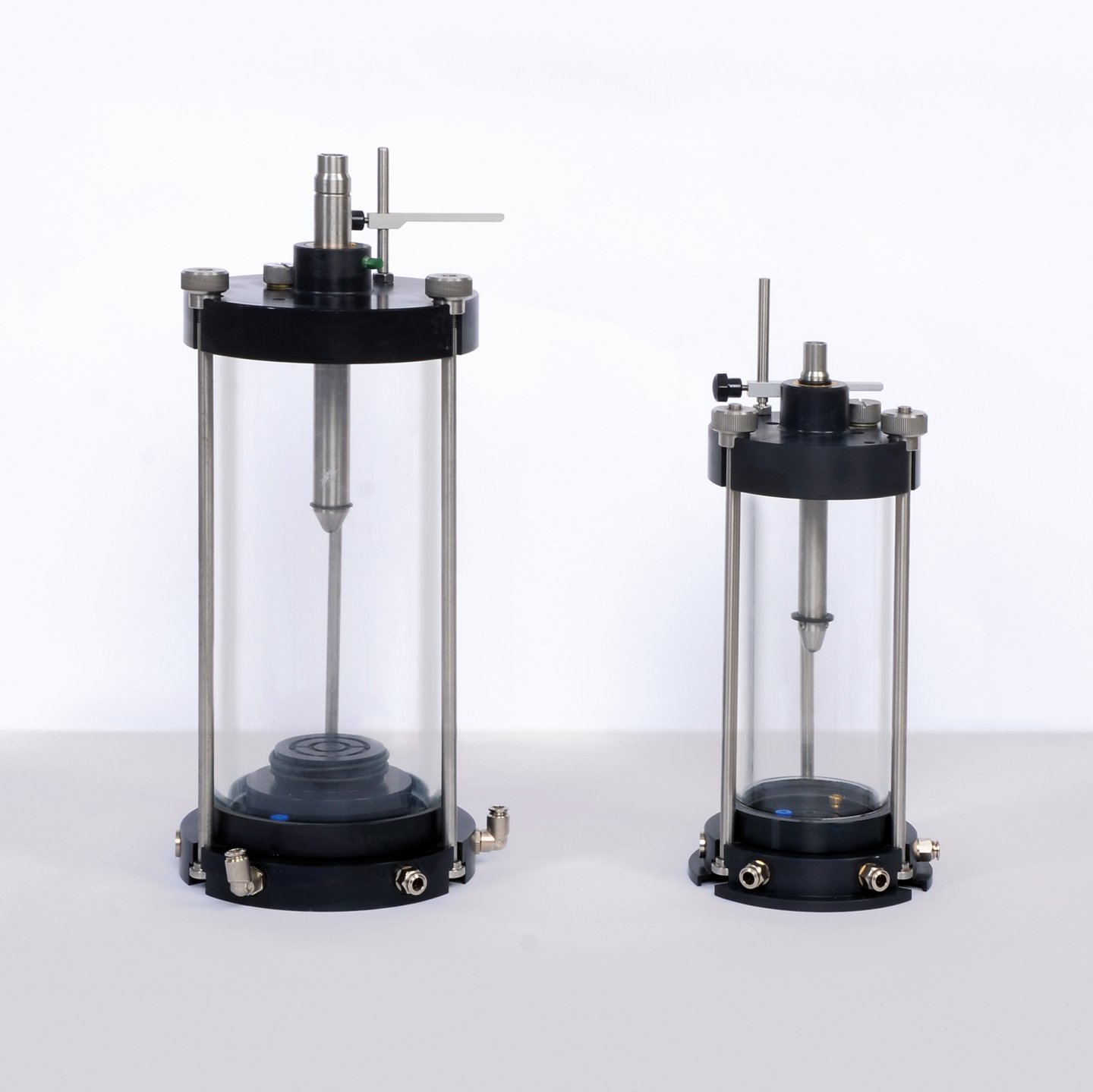
UTS-2400 |
Standard Triaxial cell for 38 and 50 mm dia. samples |
|
UTS-2401 |
Standard Triaxial cell for 70 and 100 mm dia. samples |
The cell has been designed and treated to minimize corrosion. Particular attention has been paid to the quality of finish between the piston and the head. Final assembly includes the fitting of an O-ring seal and the use of a special lubricant to reduce friction to a minimum and eliminate water leakage. The piston load capacity is designed to accept high axial loads which may be present during the final stages of a test.
Each cell has five take-off positions drilled in the base for top drainage/back pressure, pore water pressure and bottom drainage. Each cell will accept a range of base adaptors and various accessories for testing a wide range of specimens.
The cell capacity is designed to tolerate confining pressures as high as 1700 kPa which is enough for simulating most in-situ conditions.
|
|
UTS-2400 |
UTS-2401 |
|
Dimensions |
150x150x300 mm |
200x200x400 mm |
|
Weight (approx.) |
5 kg |
8 kg |
Cell Accessories
|
Sample Diameter(mm) |
38 |
50 |
70 |
100 |
UU Test |
CU CD Test |
|
Base Adaptor |
UTS-2420 |
UTS-2450 |
UTS-2470 |
UTS-2500 |
YES |
YES |
|
Top Cap |
UTS-2421 |
UTS-2451 |
UTS-0471 |
UTS-2501 |
YES |
YES |
|
Nylon Tubing for Drainage |
UTS-2422 |
UTS-2452 |
UTS-2472 |
UTS-2502 |
-- |
YES |
|
Pair of Porous Discs |
UTS-2423 |
UTS-2453 |
UTS-2473 |
UTS-2503 |
-- |
YES |
|
Rubber Membrane |
UTS-2424 |
UTS-2454 |
UTS-2474 |
UTS-2504 |
YES |
YES |
|
Membrane Placing Tool (Strecher) |
UTS-2425 |
UTS-2455 |
UTS-2475 |
UTS-2505 |
YES |
YES |
|
0 Ring (10pcs.) |
UTS-2426 |
UTS-2456 |
UTS-2476 |
UTS-2506 |
YES |
YES |
|
0 Ring Placing Tool |
UTS-2427 |
UTS-2457 |
UTS-2477 |
UTS-2507 |
YES |
YES |
|
Leteral Filter Paper (50 pcs.) |
UTS-2428 |
UTS-2458 |
UTS-2478 |
UTS-2508 |
-- |
YES |
|
Filter Paper Discs (100 pcs.) |
UTS-2429 |
UTS-2459 |
UTS-2479 |
UTS-2509 |
-- |
YES |
|
Plastic Discs (2 pcs.) |
UTS-2430 |
UTS-2460 |
UTS-2480 |
UTS-2510 |
YES |
-- |
Sample Preperation Accessories
|
Sample Diameter |
38 mm |
50 mm |
70 mm |
100 mm |
|
Split Sand Former |
UTS-2431 |
UTS-2461 |
UTS-2481 |
UTS-2511 |
|
Split Mould |
UTS-2432 |
UTS-2462 |
UTS-2482 |
UTS-2512 |
|
Cutter |
UTS-2436 |
UTS-2466 |
UTS-2486 |
UTS-2516 |
|
Aliminium Dolly |
UTS-2437 |
UTS-2467 |
UTS-2487 |
UTS-2517 |
|
Mould and hammer for preparing triaxial test specimens |
UTS-2439 |
UTS-2469 |
UTS-2489 |
UTS-2519 |
32. Oil and Water Constant Pressure System
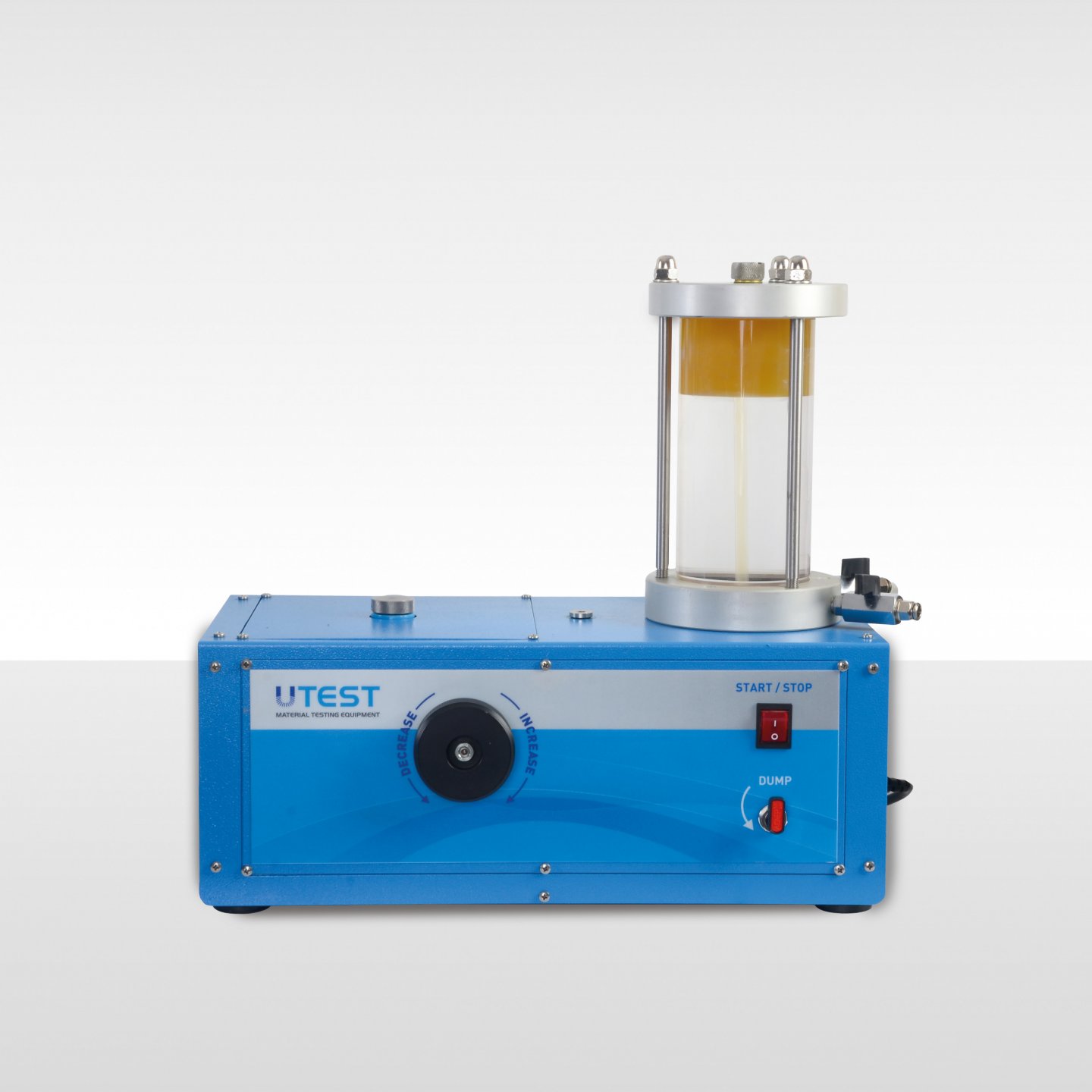
Product Code
|
UTS-2408 |
Oil and Water Constant Pressure Unit, 1700 kPa |
|
UTGE-3554 |
Digital Vacuum and Pressure Gauge, (-1…30 bar) |
|
UTGM-1420 |
Pressure Transducer, 2000 kPa |
|
Models for 220-240V 50 Hz, 1 ph |
UTS-2408 |
|
Models for 110-120V 60 Hz, 1 ph |
UTS-2408-N |
The Oil and Water Constant Pressure Unit is extremely versatile and can be used in conjunction with a wide range of test equipment. The unit provides continuous variable pressure up to 1700 kPa. Pressure is increased or decreased simply by turning a control knob.
The Unit is used for providing cell/back pressure in triaxial tests. The apparatus is supplied without a gauge for those customers who have suitable pressure monitoring equipment.
As optional equipment for monitoring the pressure of the unit;
• The Digital Pressure Gauge (UTGE-3554) or
• The pressure transducer (UTGM-1420) which can be used with UTouch Control Unit on the Multiplex Universal Electromechanic Test Machine (UTM-0108.SMPR) for only UU test or
• The pressure transducer (UTGM-1420) which should be used with UTCU-0020 for CU-CD tests
can be used and prefered optional equipment should be ordered separately.
The machine features a clear hydraulic/water interface reservoir and up to 1 liter capacity of water is available under pressure. Supplied complete with 2 liters of No.46 regular hydraulic oil.
|
Product Code |
Dimensions |
Weight |
Power |
|
UTS-2408 |
270x480x460 mm |
12 kg |
35 W |
|
UTGE-3554 |
100x100x100 mm |
1 kg |
|
33. Automatic Volume Change Unit
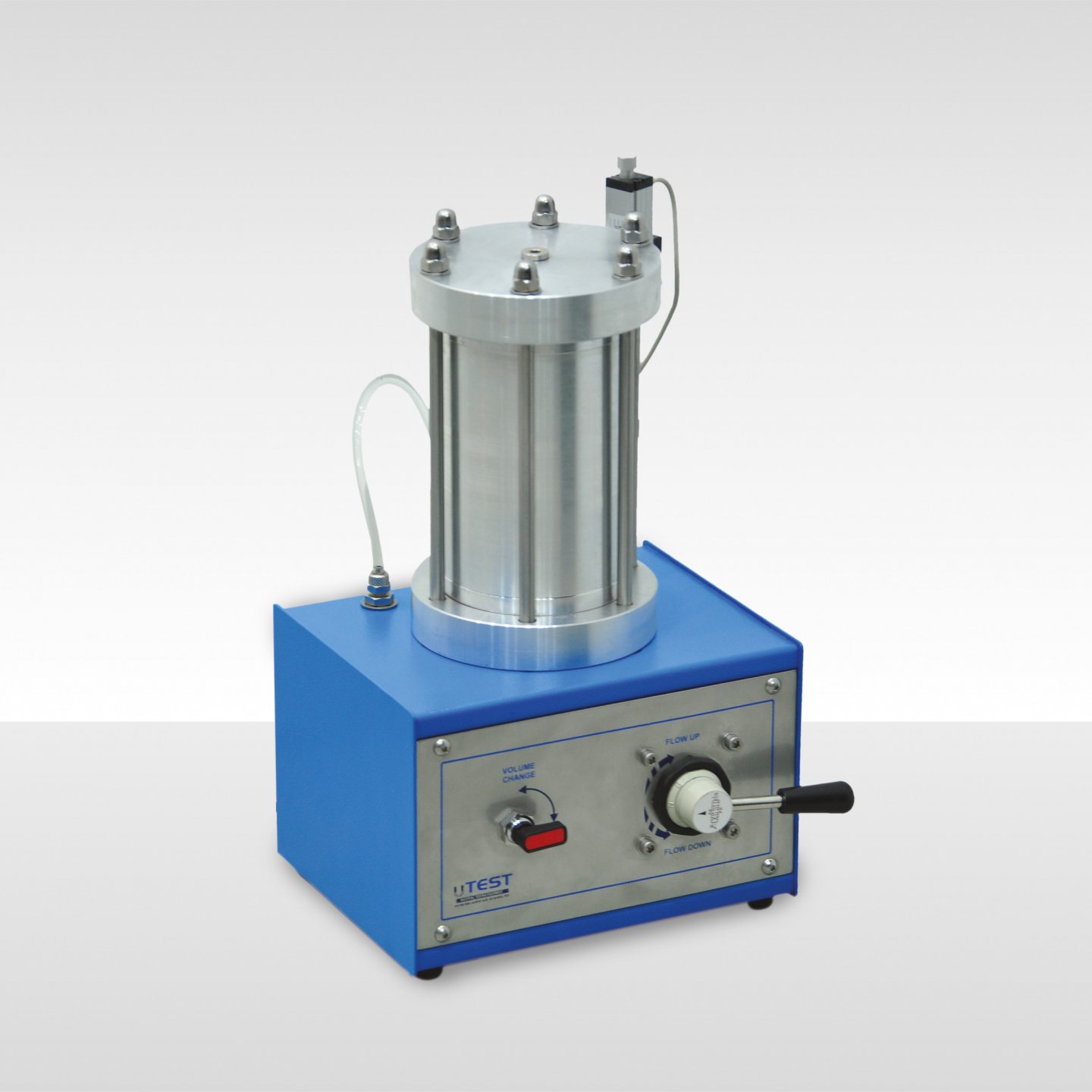
Product Code
|
UTS-2415 |
Automatic Volume Change Unit |
The Unit consists of a piston connected to a 25 mm travel linear transducer which is sealed against a precision machined calibration chamber so that the linear movement of the piston is exactly proportional to the volume of water in the calibration chamber.
The apparatus creates an electrical signal proportional to the volume of water flowing through the unit. By connecting it to the data acquisition system the measured volume change will be used by software during the test and in final report.
|
Capacity |
100 cm³ |
|
Transducer Input |
up to 12 V DC |
|
Accuracy |
± 0.1 ml |
|
Dimensions |
150x200x300 mm |
|
Weight (approx.) |
8 kg |
34. Pressure Transducer and Block for Triaxial Test Cells
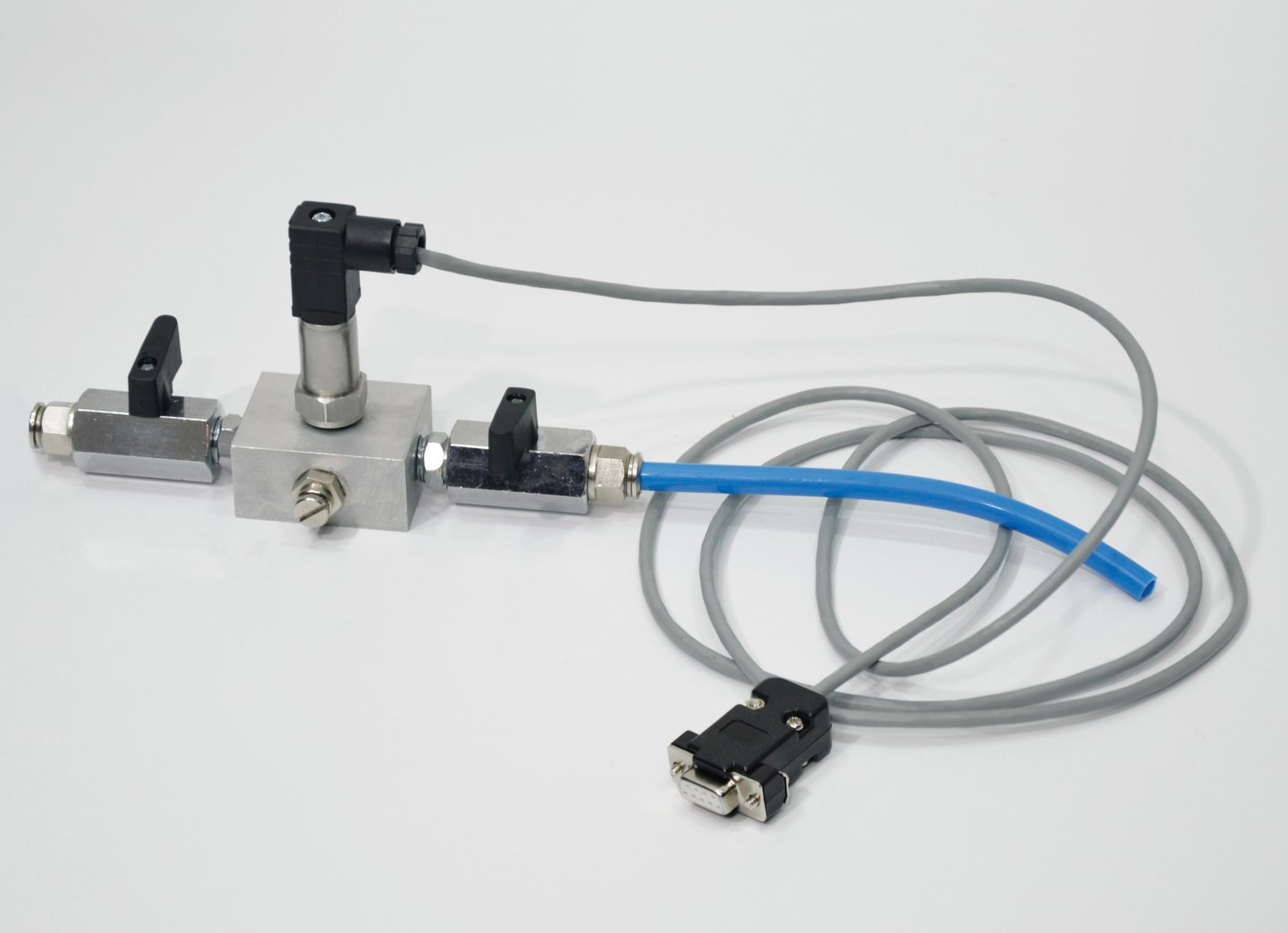
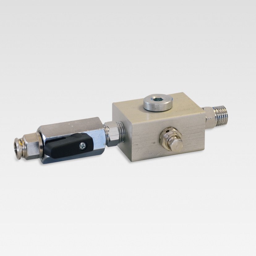
Product Code
|
UTS-2406 |
Block with one connection line and pressure transducer for triaxial test cells |
|
UTGM-1420 |
Pressure Transducer, 2000 kPa |
|
UTS-2405 |
Blockwith One Connection Line for Triaxial Test |
The Block for triaxial test cells is used for connection of the pressure transducers and de-airing in the water hoses. 3 pcs. UTS-4206 are connected to each triaxial cell.
The Pressure Transducer of the UTS-2406 is used for the measurement of lateral pressure in cell or back or pore pressure of water in triaxial test systems and also should be used with a UTouch Control Unit or a UTCU-0020 (interface unit with 4 channel for data acquisition)
35. De-Airing Water Systems
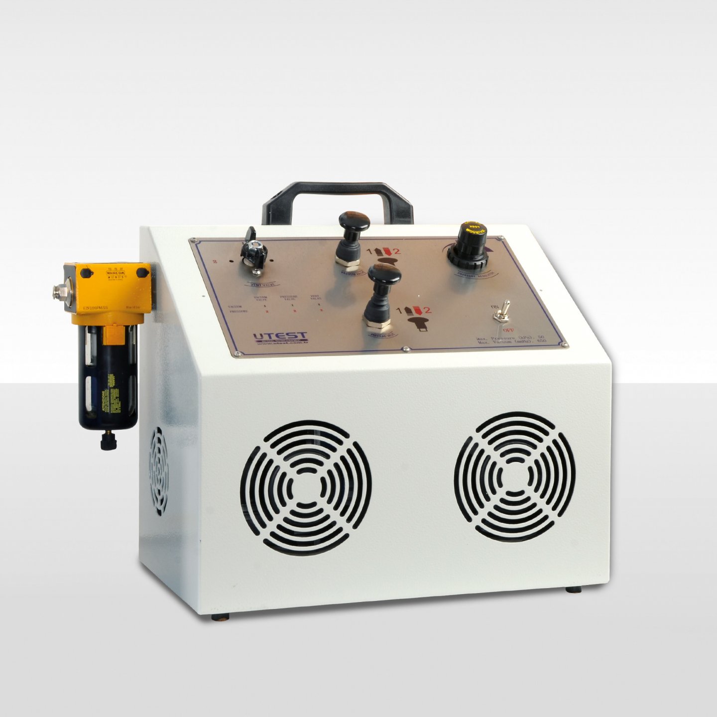
Product Code
|
UTS-2418 |
De-Airing Water Apparatus, 230V, 50Hz, 1ph |
|
UTS-1330 |
De-Airing Water Tank, 7 L. |
|
UTGE-3580 |
Vacuum Control and Water Connection Panel with Vacum Gage Manometer |
|
UTGE-3505 |
Vacuum Pump 51 L/min. Capacity, 220-240 V 50-60 Hz |
|
UTGG-2015 |
Filter Flask for Vacuum, 2000 ml |
|
UTGE-3570 |
Air Drying Unit / Water Trap, Vacuum Type |
|
UTGP-1140 |
Plastic Hose, Ø8mm OD, 3 m |
The UTS-De-Airing Water Apparatus is a compact and self-contained equipment which can de-air water quickly for geotechnical test methods. The apparatus used in conjunction with the de-airing tank (UTS-1330). Air is removed from the water by a vacuum system. De-airing tank should be ordered separately.
The first option for de-airing water;
- De-Airing Water Apparatus UTS-2418
- De-Airing Water Tank (UTS-1330)
- Vacuum Control and Water Connection Panel with Regulator and Vacum Gage Manometer (UTGE-3580) (These panel is optional)
- Plastic Hose (UTGP-1140)
The second option for de-airing water;
- Vacuum Pump (UTGE-3505),
- Filter Flask (UTGG-2016) or Air Drying Unit / Water Trap (UTGE-3570)
- De-Airing Water Tank (UTS-1330)
- Vacuum Control and Water Connection Panel with Vacum Gage Manometer (UTGE-3580) (These panel is optional)
- Plastic Hose (UTGP-1140),
By using UTGE-3580 Vacuum Control and Water Connection Panel, vacum pressure degree can be regulated . By using UTGE-3580 de-aring water equipment can be used without repeated assembling the hoses.The panels are supplied with 3m hose (UTGP-1140).
UTS-1330
UTGE-3580
UTGE-3570
|
Product Code |
Dimensions |
Weight (approx.) |
|
UTS-2418 |
240x460x380 mm |
15 kg |
|
UTGE-3580 |
300x400x100 mm |
5 kg |
|
UTS-1330 |
200x300x250 mm |
3 kg |
|
UTGG-1442 |
120x120x220 mm |
0.5 kg |
|
UTGE-3505 |
290x120x220 mm |
7 kg |
|
UTGE-3570 |
70x70x240 mm |
0,5 kg |
36. Proctor Moulds And Rammers
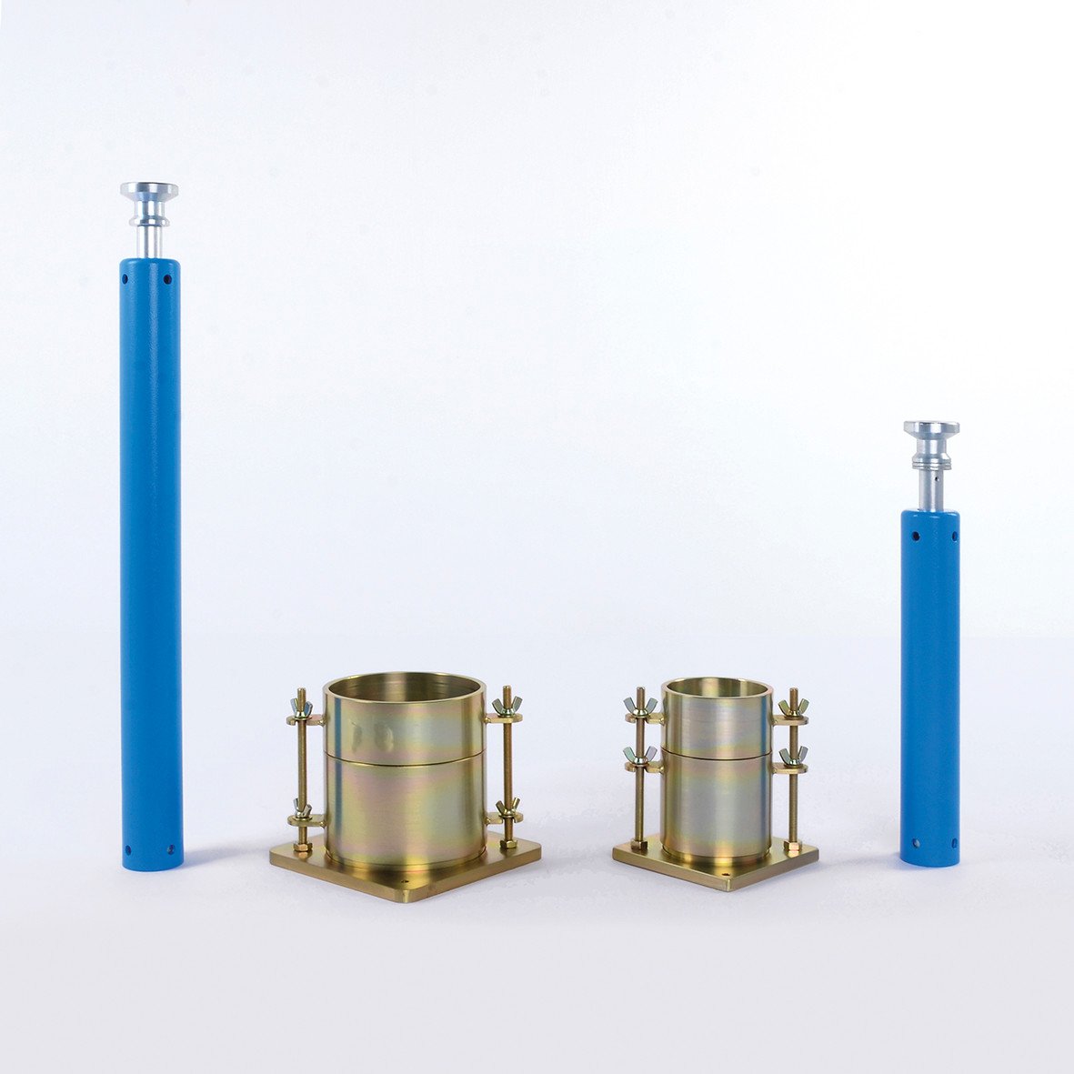
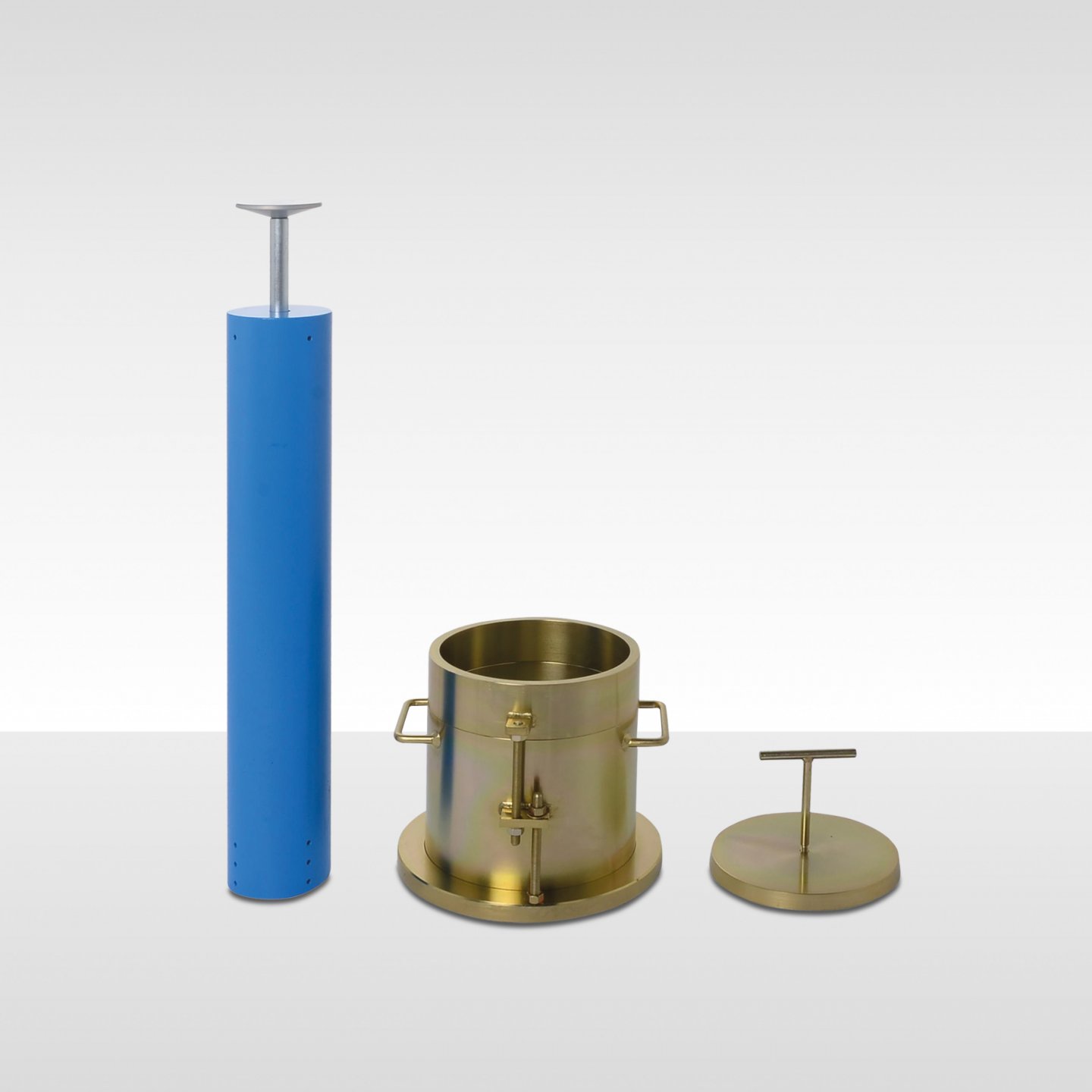
Product Code
|
UTS-0600A |
Standard Proctor Mould, ASTM |
|
UTS-0605A |
Standard Proctor Compaction Rammer, ASTM |
|
UTS-0610A |
Modified Proctor Mould, ASTM |
|
UTS-0615A |
Modified Proctor Compaction Rammer, ASTM |
|
UTS-0600E, NF |
A Type Proctor Mould (Standard), EN, NF |
|
UTS-0603E, NF |
A Type Split Proctor Mould (Standard), EN, NF |
|
UTS-0605E, NF |
A Type Proctor Compaction Rammer (Low Energy-Standard), EN, NF |
|
UTS-0607E |
Steel Plate for A Type Proctor Moulds, EN |
|
UTS-0610E, NF |
B Type Proctor Compaction Mould (Modified), EN, NF |
|
UTS-0613E, NF |
B Type (Modified) Split Proctor/CBR Split Mould, EN, NF |
|
UTS-0615E, NF |
B Type Proctor Compaction Rammer (Medium Energy-Modified), EN, NF |
|
UTS-0617E |
Steel Plate for B Type Proctor Moulds, EN |
|
UTS-0620E |
C Type Proctor Compaction Mould, EN |
|
UTS-0625E |
C Type Proctor Compaction Rammer (High Energy), EN |
|
UTS-0627E |
Steel Plate for C Type Proctor Moulds, EN |
|
UTS-0600B.TS |
1 Liter Mould (Standard Proctor), BS, TS 1900-1 |
|
UTS-0605B |
2.5 kg Compaction Rammer, BS |
|
UTS-0610B.E |
Modified Proctor (CBR Type Mould), BS (Modified Proctor)/ Vibrating Hammer Mould BS, EN, TS 1900-1 |
|
UTS-0615B |
4.5 kg Compaction Rammer, BS |
|
UTS-0600NF |
Standard Proctor Mould, NF |
|
UTS-0603NF |
Split Standard Proctor Mould, NF |
|
UTS-0605NF |
Standard Proctor Compaction Rammer, NF |
|
UTS-0610NF |
CBR Type Mould (Modified Proctor), NF |
|
UTS-0613NF |
Split CBR Type Mould (Modified Proctor), NF |
|
UTS-0615NF |
Modified Proctor Compaction Rammer, NF |
|
UTS-0600AS |
A type Proctor Mould (Standard), AS |
|
UTS-0605AS |
Standard Proctor Compaction Rammer with Round Foot. AS |
|
UTS-0606AS |
Standard Proctor Compaction Rammer with Sector Foot. AS |
|
UTS-0610AS |
B type Proctor Compaction Mould (Modified), AS |
|
UTS-0615AS |
Modified Proctor Compaction Rammer with Round Foot. AS |
|
UTS-0616AS |
Compaction Rammer with Sector Foot. AS |
Standards
ASTM D 698, D 1557, D 558 ; AASHTO T 99, T180, T 134 ; EN 13286-2;
BS 1377:4, 1924:2; NF P 94-093 (Alternative); AS 1289.5.1.1 and 5.1.2
Moulds and rammers are used for determining the relationship between the moisture content and density of compacted soil. Made of plated steel, includes collar, mould body and base plate. Rammers are used to compact the soil sample in the Proctor Moulds and made of plated steel. Different models are available conforming to the relevant standards.
According to NF P 94-093, proctor moulds and rammers that include “…NF”, can be used as an alternative to the moulds and rammers that include “…E” which also in compliance with EN 13286-2.
Proctor Moulds - ASTM/AASHTO
|
Product Code |
Description |
Internal Dia |
Body Height |
Volume |
Weight |
|
UTS-0600A |
Standard Proctor Mould |
101.6 ± 0.4 mm |
116.4 ± 0.5 mm |
944.0 ± 14 mm cm3 |
4 kg |
|
UTS-0610A |
Modified Proctor Mould |
152.4 ± 0.7 mm |
116.4 ± 0.5 mm |
2124 ± 25 mm cm3 |
8 kg |
Proctor Moulds - EN; NF
|
Product Code |
Description |
Internal Dia |
Body Height |
Volume |
Weight |
|
UTS-0600E, NF |
A Type Proctor Mould EN, NF (Standard) |
100 ± 1 mm |
120± 1 mm |
942 cm3 |
6 kg |
|
UTS-0603E, NF |
A Type Split Proctor Mould (Standard), EN, NF |
100 ± 1 mm |
120± 1 mm |
942 cm3 |
6 kg |
|
UTS-0610E, NF |
B Type (Modified) Proctor/CBR Mould EN, NF |
150 ± 1 mm |
120 ± 1 mm |
2120 cm3 |
10 kg |
|
UTS-0613E, NF |
B Type (Modified) Split Proctor/CBR Mould, EN, NF |
150 ± 1 mm |
120 ± 1 mm |
2120 cm3 |
10 kg |
|
UTS-0620E |
C Type Proctor Mould (Standard), EN |
250 ± 1 mm |
200 ± 1 mm |
9813 cm3 |
12 kg |
Proctor Moulds - BS
|
Product Code |
Description |
Internal Dia |
Body Height |
Volume |
Weight |
|
UTS-0600B.TS |
1liter Mould (Standard Proctor) BS,TS-1900-1 |
105 ± 0.5 mm |
115,5± 0,5 mm |
1000 cm3
|
5 kg |
|
UTS-0610B.E |
(Modified Proctor) (CBR Type Mould) Vibrating Hammer Mould BS, EN, TS-1900-1 |
152 ± 0.5 mm |
127 ± 1 mm |
2303 cm3 |
7 kg |
*C Spanners (UTS-00611B.E) and Assembly Tool (UTS-0612B.E) should be ordered separately for assembling and disassembling the these moulds.
Proctor Moulds - NF P 94-093 (Alternative)
|
Product Code |
Description |
Internal Dia |
Body Height |
Volume |
Weight |
|
UTS-0600NF |
Standard Proctor Mould, NF |
101,5± 0.5 mm |
116,5± 0,5 mm
|
942 cm3 |
5 kg |
|
UTS-0603NF |
Split Standard Proctor Mould, NF |
101,5± 0.5 mm |
|||
|
UTS-0610NF |
Modified Proctor (CBR Type) Mould, NF |
152 ± 0.5 mm |
152,0± 0,5 mm |
2757 cm3 |
15 kg |
|
UTS-0613NF |
Split Modified Proctor (CBR Type) Mould, NF |
152 ± 0.5 mm |
Proctor Moulds - AS
|
Product Code |
Description |
Internal Dia |
Body Height |
Volume |
Weight |
|
UTS-0600AS |
A Type Proctor Mould AS (Standard) |
105 ± 0.5 mm |
115,5± 0,5 mm |
1000 cm3
|
6 kg |
|
UTS-0610AS |
B Type Proctor Mould AS (Modified) |
152 ± 1 mm |
132,5 ± 0,5 mm |
2400 cm3 |
10 kg
|
Proctor Rammer - ASTM / AASHTO
|
Product Code |
Description |
Rammer Dia. |
Free Fall Height |
Mass of Rammer |
Weight |
|
UTS-0605A |
Standard Proctor Compaction Rammer |
50.8 |
304.8± 1 |
2495 ± 9 g |
9 |
|
UTS-0615A |
Modified Proctor Compaction Rammer |
50.8 |
457 ± 1.3 |
4536 ± 9 g |
5 |
Proctor Rammers - EN; NF
|
Product Code |
Description |
Rammer Dia. |
Free Fall Height |
Mass of Rammer |
Weight |
|
UTS-0605E, NF |
A Type Rammer EN, NF (Low Energy-Standard) |
50 ± 0.5 |
305± 3 |
2500 ± 20 g |
5 |
|
UTS-0615E, NF |
B Type Rammer EN, NF (Medium Energy-Modified) |
50 ± 0.5 |
457 ± 3 |
4500 ± 40 g |
8 |
|
UTS-0625E |
C Type Proctor Compaction Rammer (High Energy), EN |
125 ± 0.5 |
600 ± 3 |
15000 ± 40 g |
15 |
Proctor Rammers - BS
|
Product Code |
Description |
Rammer Dia. |
Free Fall Height |
Mass of Rammer |
Weight |
|
UTS-0605B |
2.5 kg Compaction Rammer BS |
50 ± 0.5 |
300± 3 |
2500 ± 25 g |
5 |
|
UTS-0615A |
4.5 kg Compaction Rammer BS |
50 ± 0.5 |
450 ± 4 |
4500 ± 50 g |
4,50 |
Proctor Rammers - NF P 94-093 (Alternative)
|
Product Code |
Description |
Rammer Dia. |
Free Fall Height |
Mass of Rammer |
Weight |
|
UTS-0605NF |
Standard Proctor Compaction Rammer, NF |
51 ±1,0 |
305± 2 |
2490±2,5 g |
5 |
|
UTS-0615NF |
Modified Proctor Compaction Rammer, NF |
51 ±1,0 |
457 ±2 |
4535 ± 5 g |
8 |
Proctor Rammers - AS
|
Product Code |
Description |
Rammer Dia. |
Free Fall Height |
Mass of Rammer |
Weight |
|
UTS-0605AS |
Standard Proctor Compaction Rammer with Round Foot. AS |
50±0,4 |
300±2,0 |
2,7±0,01 kg |
4 |
|
UTS-0606AS |
Standard Proctor Compaction Rammer with Sector Foot. AS |
74±0,5 (Radius of sector foot) |
300±2,0 |
2,7±0,01 kg |
4 |
|
UTS-0615AS |
Modified Proctor Compaction Rammer with Round Foot. AS |
50±0,4 |
450±2,0 |
4,9±0,01 kg |
8 |
|
UTS-0616AS |
Modified Proctor Compaction Rammer with Sector Foot. AS |
74±0,5 (Radius of sector foot) |
450±2,0 |
4,9±0,01 kg |
8 |
37. Automatic Soil Compactor
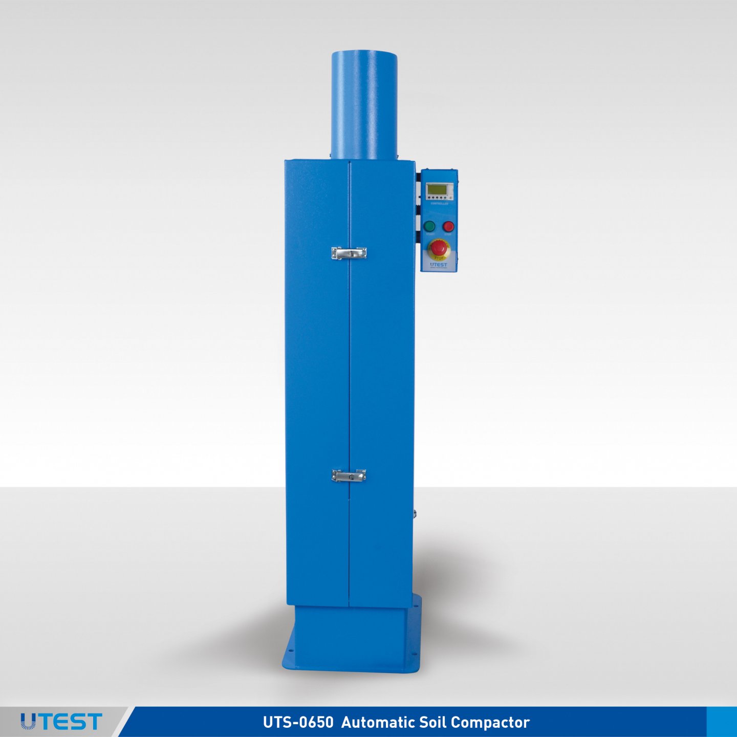
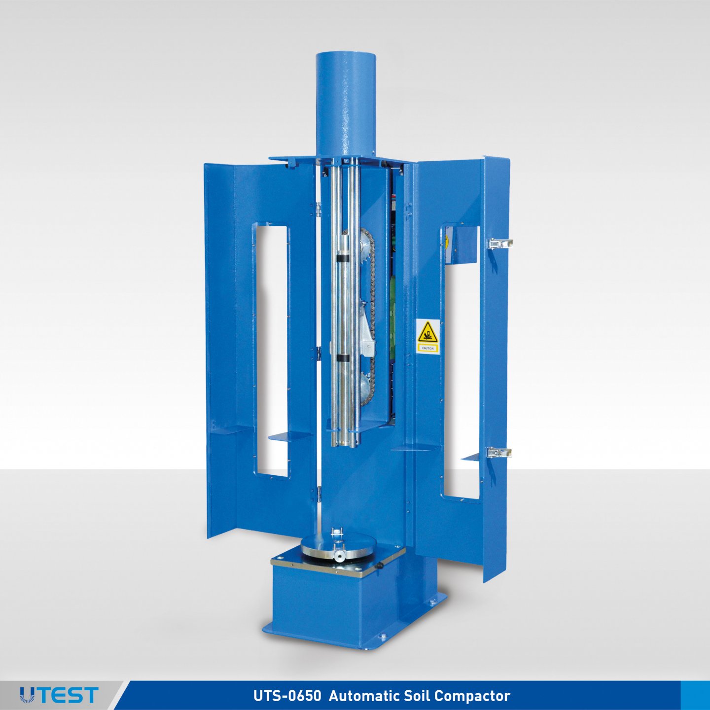
Product Code
|
UTS-0650 |
Automatic Soil Compactor, BS, EN, NF, ASTM, AASHTO |
|
UTS-0650AS |
Automatic Soil Compactor, AS |
|
UTS-0652 |
ASTM/EN/NF/BS Rammer for UTS-0650 |
|
UTS-0654 |
ASTM Rammer Face, Ø2” (50.8 mm) for UTS-0650 |
|
UTS-0656 |
EN/NF/BS Rammer Face Ø 50 mm for UTS-0650 |
|
Models for 220-240V 50 Hz, 1 ph. |
UTS-0650-T |
UTS-0650AS-T |
|
Models for 110-120V 60 Hz, 1 ph. |
UTS-0650-N |
|
|
Models for 220-240V 60 Hz, 1 ph. |
UTS-0650-K |
Standards
ASTM D558, D559, D560, D698, D1557, D1883; EN 13286 2, 13286-47; NF P94-093, P94-078; BS 1377:4 AASHTO T99, T134, T135, T136, T180, T193; AS 1289.5.1.1, 5.2.1, 6.1.1
Automatic Soil Compactor are designed to compact specimens automatically and uniformly, assuring conformity with the above listed international standards.
The principle of the design is to allow the hammer to drop the required height into the soil in the mould which rotates circularly to distribute the blows uniformly over the surface of the specimen in the mould. The drop height is adjustable to 300 mm, 12” (305 mm), 450 mm and 18” (457 mm). The rammer is circular faced and interchangeable to 50 mm or 2” (50.8 mm).diameter. Rammer weight is adjustable according to reference standard. When compacting 100 mm or 4” diameter specimens the unit operates on a single radius and when compacting 150 mm or 6” diameter specimens the unit operates on inner and outer radius to obtain even compaction.
The number of blows per layer can be set at the beginning of the compaction process by the digital counter according to the standard preferred by user. This automatic blow pattern ensures effective and equal compaction for each layer of soil by rotating the base table, so the mould, in equal steps and travelling the rammer across the mould. User defined blow number and in-out distribution is also available.
Compactor is equipped with programmable digital counter which allows the machine;
- To select reference standard ( number of blows and mould size ) by the operator at the beginning of the test.
- To set desired compaction cycle ( number of blows and count of the number of inner and outer drops) by user.
The standard type (BS, EN, NF, ASTM, AASHTO) mould size (4’’/100 mm or 6’’/150 mm) and the number of drops can be selected easily.
UTS-0650 Soil Compactor is supplied complete with;
- ASTM/EN/NF/BS Rammer
- ASTM Rammer Face, Ø2” (50.8 mm)
- EN/NF/BS Rammer Face, Ø 50 mm
UTS-0650AS Soil Compactor is supplied complete with;
- AS Rammer
|
Dimensions |
400x550x1470 mm |
|
Weight (approx.) |
125 kg |
|
Power |
370 W |
38. Automatic Mechanical Compactor
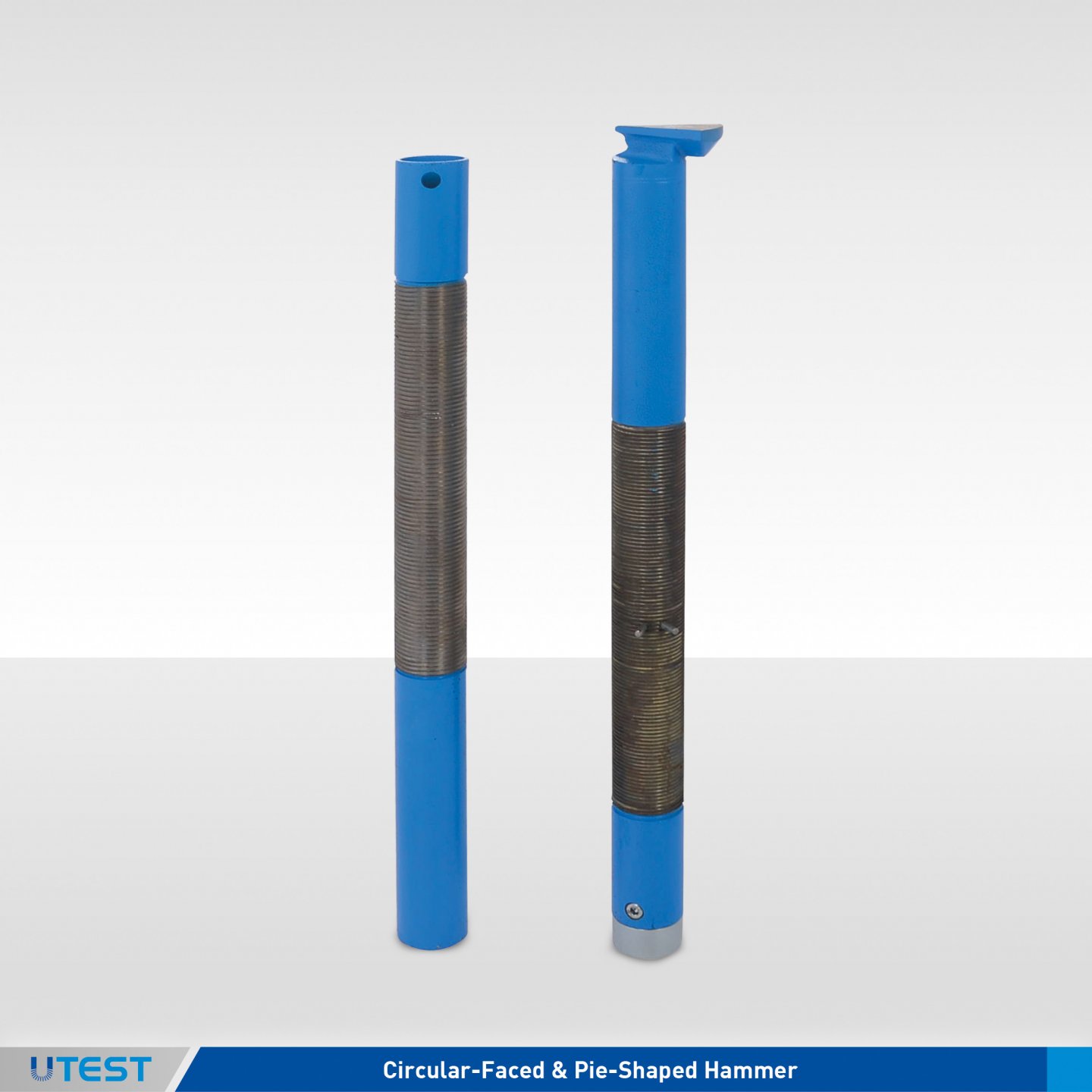
Product Code
|
UTS-0660 |
Automatic Soil Compactor only ASTM |
|
Models for 220-240V 50 Hz, 1 ph. |
UTS-0660-T |
|
Models for 110-120V 60 Hz, 1 ph. |
UTS-0660-N |
|
Models for 220-240V 60 Hz, 1 ph. |
UTS-0660-K |
Standards
ASTM D558, D559, D560, D698, D1557, D1883
The UTS-0660 Automatic Mechanical Compactor is designed to perform fast and accurate compaction of soil samples automatically acc. to ASTM standards. The weights of rammers are adjustable to 5,5 lbf (2,5 kg) or 10 lbf(4,5 kg).Also the drop heights of rammers are adjustable to 18”(457mm) or 12”(305mm).The pie-shaped rammer can only be used for 6 "mold compaction while the circular-faced rammer can only be used for 4" mold compaction.Hammers can easily be replaced from the front side of the compactor.
Machine stops automatically after preset number of blows per compaction is completed. Compaction mould is mounted on the round base; the circular base indexes automatically with each blow to ensure uniform sample compaction.
The Automatic Mechanical Compactor is supplied complete with;
- Circular-Faced Rammer, Ø2”
- Pie-Shaped Rammer
|
Dimensions |
16,5”x22,5”x55,1” (420x570x1400 mm) |
|
Weight (approx.) |
287 lbs (130 kg) |
|
Power |
600 W |
39. Vibratory Compaction
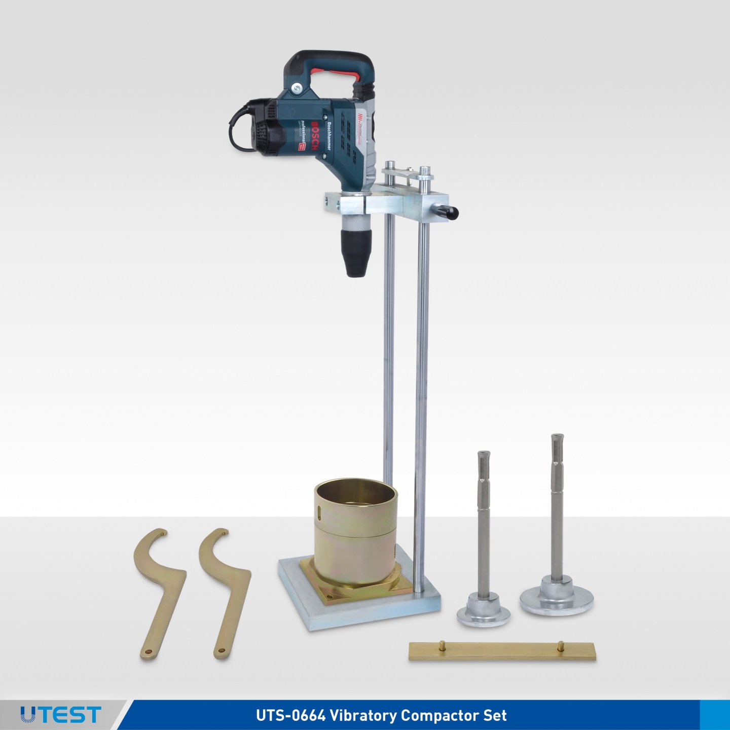
Product Code
|
UTS-0681-T |
Vibratory Hammer for Compaction of Soil and Bituminous Mixtures, 220-240V, 50 Hz, 1ph. |
|
UTS-0682 |
Steel Tamper, Ø146 mm |
|
UTS-0683 |
Steel Tamper, Ø102 mm |
|
UTS-0610B.E |
CBR Type Mould BS (modified proctor) / Vibrating Hammer Mould EN |
|
UTS-0611B.E |
C Spanner for UTS-0610B.E, 2 pcs |
|
UTS-0612B.E |
Assembly Tool for Base Plate for UTS-0610B.E |
Standards
EN 13286-4; BS 1377:4 / EN 12697-9, 12697-10, 12697-32
The UTS-0681-T Vibratory compaction apparatus are used t for preparing the test specimens of road base and sub base materials and bituminous mixtures
UTS-0682 and UTS-0683 the steel tampers which include a tamping foot and a shank(UTS-0684) should be ordered separately when ordering the vibratory hammer.
Also, UTS-0610B.E mould should be ordered separately and also when ordering this mould, UTS-0611B.E and UTS-0612B.E should be ordered separately for assembling and dissambling.
|
Dimensions |
350x550x1300 mm |
|
Weight (approx.) (UTS-0681-T) |
105 kg |
|
Impact Rate |
3000-1500 |
|
Power |
1150 W (vibrating hammer) |
40. Relative Density Test Set
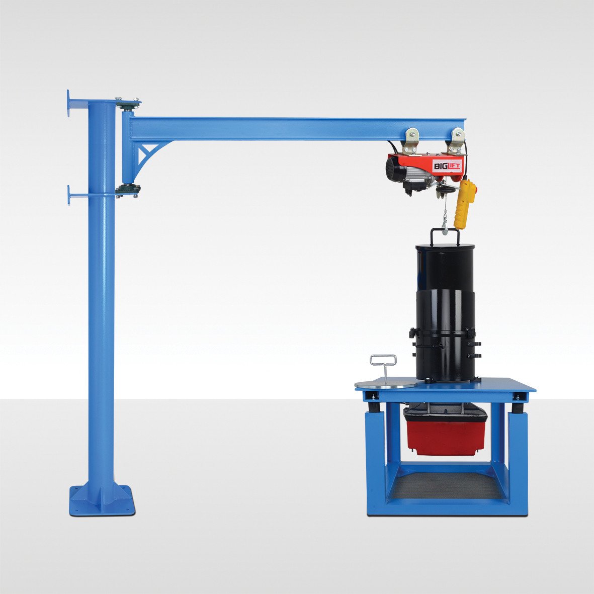
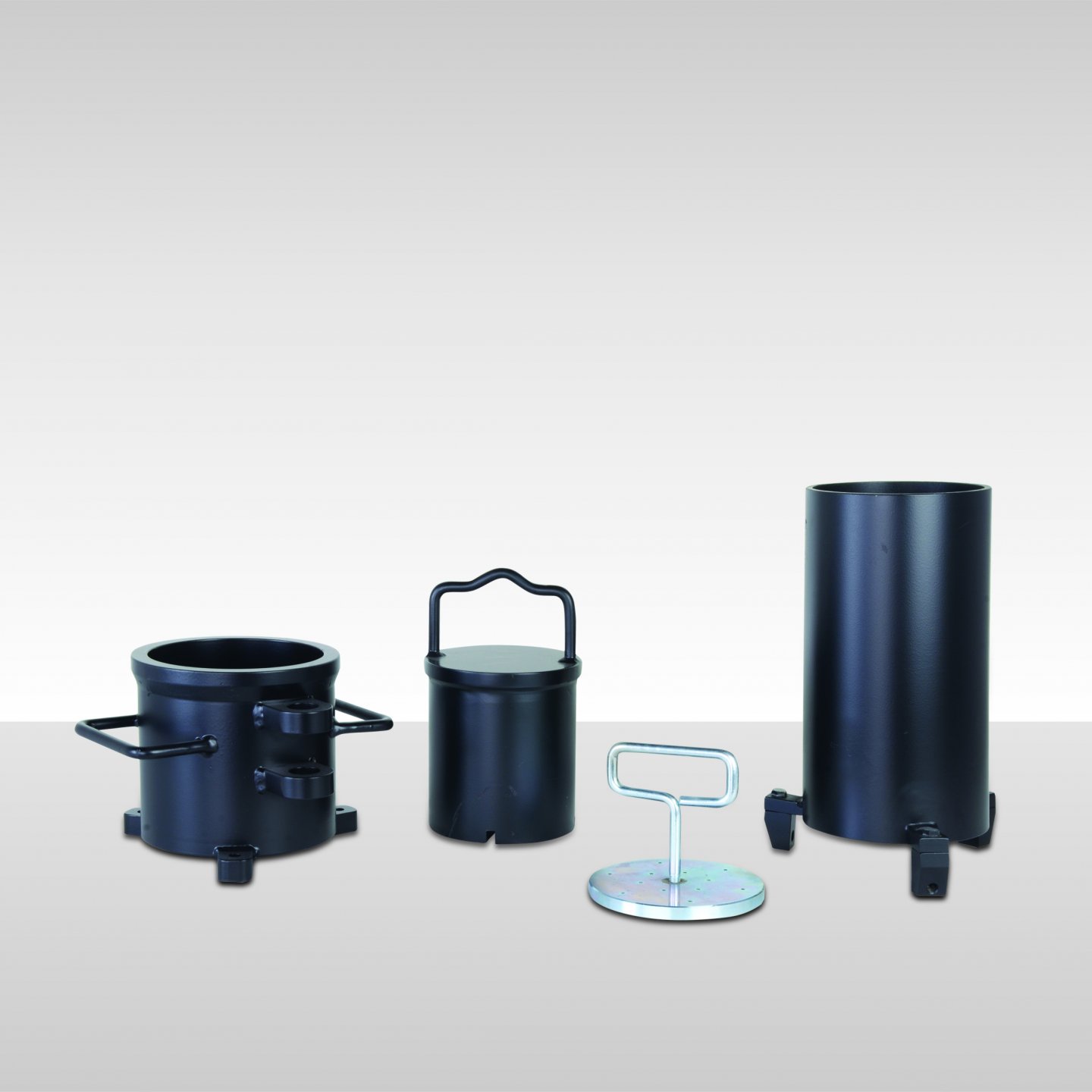
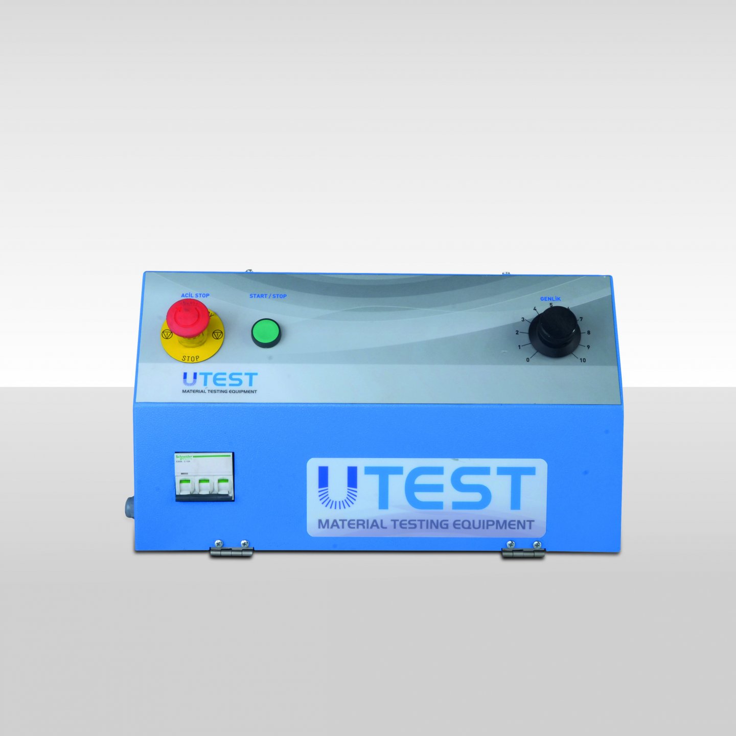
Product Code
|
UTS-0670A-C |
Relative Density Test Set, ASTM, 380V 50Hz, 3 ph |
|
UTS-0672A |
Relative Density Mould Set, ASTM, 0.5 ft³ |
|
UTS-0673A |
Relative Density Mould Set, ASTM, 0.1 ft³ |
|
UTS-0674A |
Relative Density Gauge Set, ASTM |
|
UTS-0675 |
Pouring Funnel Set, for Relative Density Test |
|
UTS-0676 |
Compass Crane with Electric Motor |
Standards
ASTM D4253 (Method 1A—1B), D4254
Relative Density Test Set acc.to ASTM is used for the determination of the relative density of cohesionless soil for which impact compaction will not produce a well defined moisture-density relationship curve and where the maximum density of impact method will generally be less than by vibratory method. The test is applicable to soils that may contain up to 15 %, by dry mass, of soil particles passing a No 200 (75-μm) sieve, provided they still have cohesionless, free-draining characteristics. Further, these test methods are applicable to soils in which 100 %, by dry mass of soil particles pass a 3-in. (75-mm) sieve.
|
Vibration Frequency |
50 Hz |
|
Amplitude Range |
Between about 0.20 mm and 0.48 mm |
|
Vibrating Table Type |
Electromagnetic |
UTS-0670A-C, Relative Density Test Set consists of a electromagnetic vibrating table with controller, relative density mold sets (0,1 ft.3 and 0,5 ft.3) and relative density gauge set.
UTS-0672A or UTS-0673A, Relative Density Mould Set consists of a mould, circular surcharge weight with handle, surcharge base plate with handle and detachable guide sleeve with clamp assembly.
UTS-0674A, Relative Density Gauge Set consists of a analog displacement dial gauge (50 x 0.01 mm division, 0-100 scale - UTGM-0132) with holder and calibration bar, metal 75 x 300 x 6mm set.
UTS-0676, Cross Crane with Elelectric Motor is used for handling of surcharge weights for user healty during the test. The Crane be anchored to a rigid wall and/or concrete ground.
UTS-0675, UTS-0676 should be ordered seperately.
|
Product Code |
Dimensions |
Weight (approx.) |
|
UTS-0670A-C |
570x760x1400 mm |
135 kg |
|
UTS-0672A |
390x390x490 mm |
130 kg |
|
UTS-0673A |
240x240x490 mm |
45 kg |
|
UTS-0674A |
100x100x320 mm |
1,8 kg |
|
UTS-0675 |
170x170x530 mm |
8 kg |
|
UTS-0676 |
400x1850x2100 mm |
95 kg |
|
Complete Set |
1100x1820x2300 mm |
400 kg |
41. Proctor Penetrometers
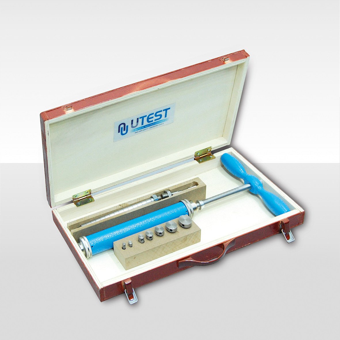
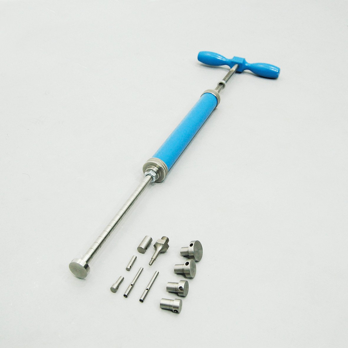
Product Code
|
UTS-0695 |
Spring Type Proctor Penetrometer |
|
UTS-0696 |
Needle Set for Proctor Penetrometer (28.55, 24.79, 20.22, 16.54, 12.83, 9.07, 6.40, 5.23 and 4.52 mm diameters) |
Standards
ASTM D1558
The UTS-0695 Spring Type Proctor Penetrometer is used for establishing the moisture-penetration resistance relation of finegrained soils. The apparatus consists of a spring loading device which is graduated from 10 to150 lbf in 2 lbf subdivisions.
Needle Set for Proctor Penetrometer consist of interchangeable needle points of 28.55, 24.79, 20.22, 16.54, 12.83, 9.07, 6.40, 5.23, 4.52 mm diameters and a carrying case.
|
Dimensions |
550x300x60 mm (packed) |
|
Weight (approx.) |
5 kg |
42. CBR Mould and Accessories ASTM
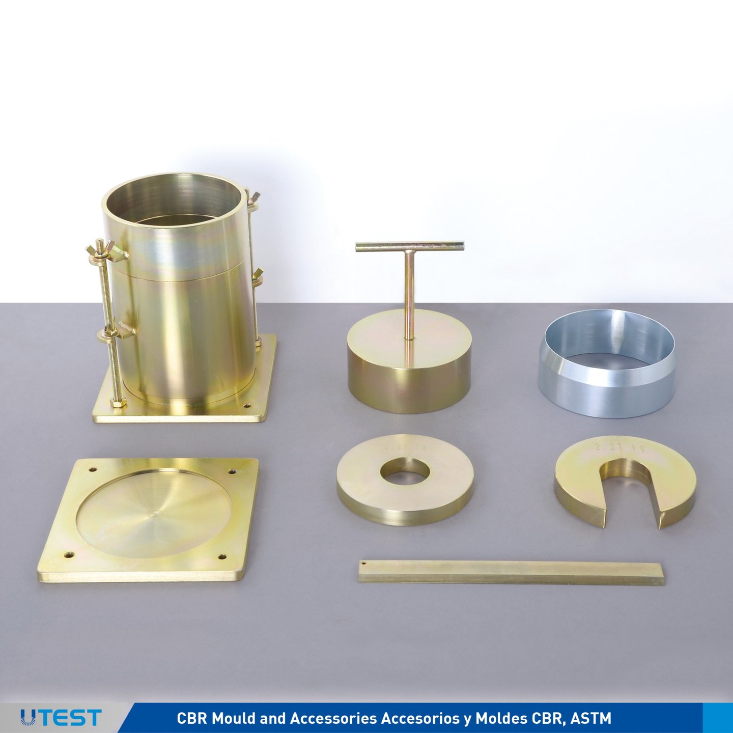
Product Code
CBR Mould and Accessories ASTM
Standards
ASTM D1883
Each accessories listed below should be ordered separately.
|
Product Code |
Description |
Dimensions |
Weight (approx.) |
|
UTS-0700A |
CBR Mould ASTM plated steel mould body with 6" (152.4 mm) dia. x 7" (177.8 mm) height, supplied complete with extension collar and perforated base plate |
200x200x240 mm |
8 kg |
|
UTS-0705A |
Spacer Disc with T handle ASTM, 150.8 mm dia. x 61.4 mm height" |
150x150x250 mm |
9 kg |
|
UTS-0708A |
Annular Surcharge Weight ASTM |
150x150x20 mm |
2,27 kg |
|
UTS-0710A |
Slotted Surcharge Weight ASTM |
150x150x100 mm |
2,27 kg |
|
UTS-0712A |
CBR Solid Base Plate ASTM |
200x200x10 mm |
3 kg |
|
UTS-0724A |
Straightedge |
300x30x9 mm |
0,30 kg |
|
UTS-0725 |
Cutting Edge |
100x100x100 mm |
0,50 kg |
|
UTS-0729 |
Filter Paper for CBR Test No: 1x152,4 mm dia. (Pack of 100) |
160x160x30 mm |
0,20 kg |
|
UTS-0730 |
Filter screen, 144 mm dia. 150 μm mesh ASTM |
150x150x10 mm |
0,10 kg |
43. CBR Mould and Accessories EN
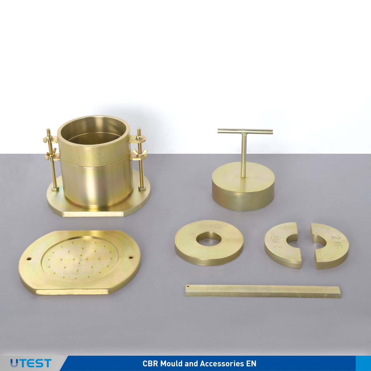
Product Code
CBR Mould and Accessories EN
Standards
EN 13286-47
Each accessories listed below should be ordered separately.,
|
Product Code |
Description |
Dimensions |
Weight (approx.) |
|
UTS-0610E, NF |
B type Modified Proctor/CBR Mould EN, NF, int dia.: 150 mm, int height: 120 mm, supplied complete with extension collar and solid base plate |
200x240x180 mm |
8,9 kg |
|
UTS-0613E, NF |
B type Modified Split Proctor/CBR Mould EN, NF, int .dia.: 150 mm, int. height: 120 mm, supplied complete with extension collar and solid base plate |
200x240x180 mm |
9,1 kg |
|
UTS-0705E |
Spacer Disc with T Handle, EN |
150x150x170 mm |
5 kg |
|
UTS-0708E.B |
Annular Surcharge Weight BS / EN |
150x150x20 mm |
2 kg |
|
UTS-0709E.B |
Split Surcharge Weight BS / EN |
150x150x20 mm |
2 kg |
|
UTS-0713E |
CBR Perforated Base Plate EN |
180x180x30 mm |
3 kg |
|
UTS-0724E |
Straightedge |
300x30x5 mm |
0,3 kg |
|
UTS-0727 |
Filter papers for CBR test, No:1 x 150 mm dia. |
160x160x30 mm |
0,2 kg |
|
UTS-0730 |
Filter screen, 144 mm dia. 150 μm mesh |
160x160x30 mm |
0,2 kg |
44. CBR Mould and Accessories BS
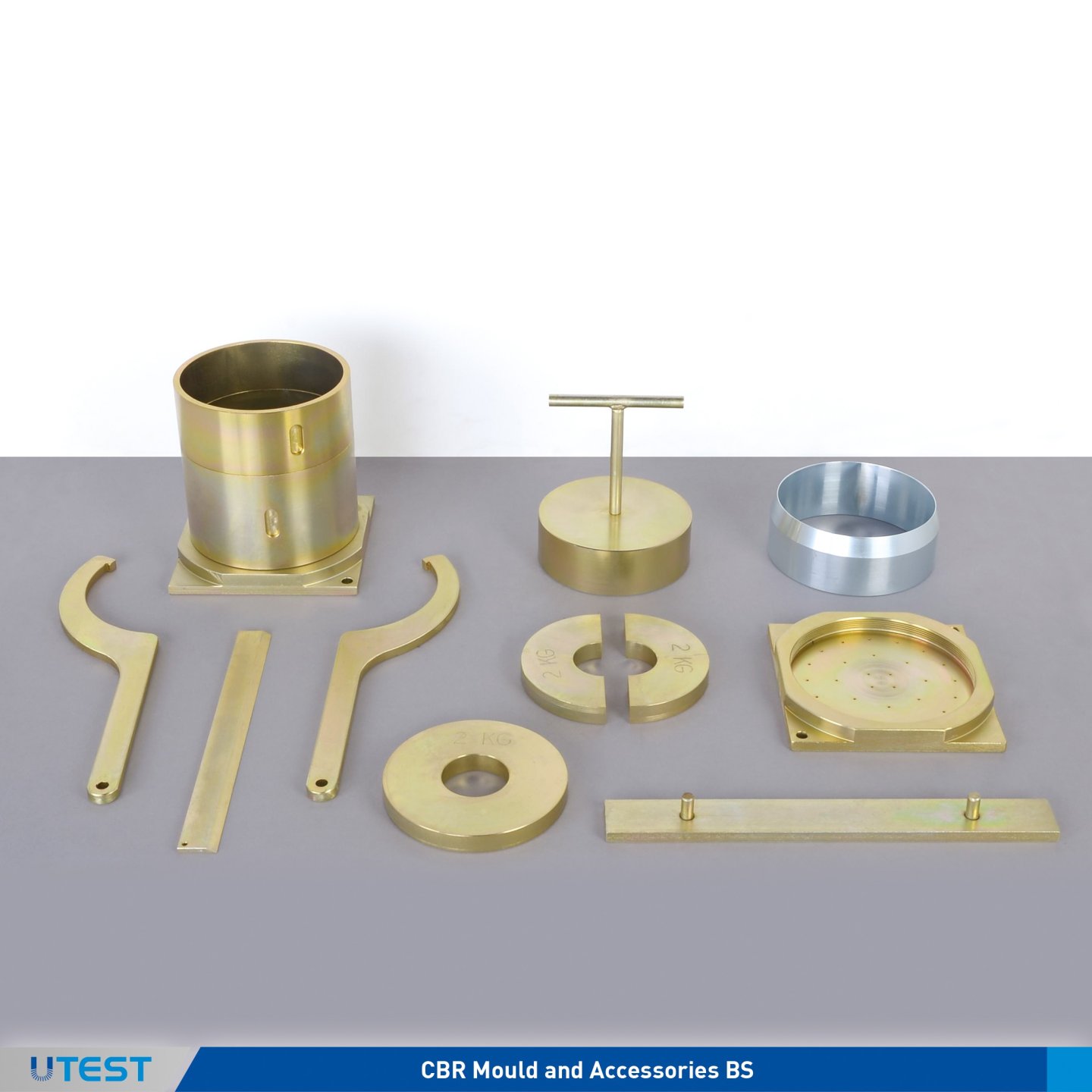
Product Code
CBR Mould and Accessories BS
Standards
BS 1377:4, 1924:2
Each accessories listed below should be ordered separately.
|
Product Code |
Description |
Dimensions |
Weight (approx.) |
|
UTS-0610B.E (*) |
CBR Type Mould BS (modified proctor) / Vibrating Hammer Mould EN, internal dia.: 152 mm, internal height: 127mm, supplied complete with extension collar and solid base plate |
180x180x190 mm |
7 kg |
|
UTS-0611B.E |
C- Spanner for UTS-0610B.E, 2 pcs |
110x380x10 mm |
0,90 kg |
|
UTS-0612B.E |
Assembly tool for Base Plate for UTS-0610B.E |
40x350x10 mm |
1 kg |
|
UTS-0725 |
Cutting Collar |
100x100x100 mm |
0,50 kg |
|
UTS-0707B |
Compaction plug with T handle BS, 150 mm dia. x 50 mm height |
150x150x190 mm |
7 kg |
|
UTS-0708E.B |
Annular Surcharge Weight BS/EN |
150x150x20 mm |
2 kg |
|
UTS-0709E.B |
Split Surcharge Weight BS/EN |
150x150x20 mm |
2 kg |
|
UTS-0713E |
CBR Perforated Base Plate BS |
180x180x30 mm |
3 kg |
|
UTS-0724E |
Straightedge |
300x300x5 mm |
0,30 kg |
|
UTS-0727 |
Filter Paper for CBR Test No:1 x 150 mm dia. (Pack of 100) |
160x160x30 mm |
0,20 kg |
(*) C-spanner (2pcs UTS-0611B.E) and Assembly Tool for Base Plate (UTS-0612B.E) should be oredered seperately. (Dismantling and installing the molds.)
45. CBR Mould and Accessories AS
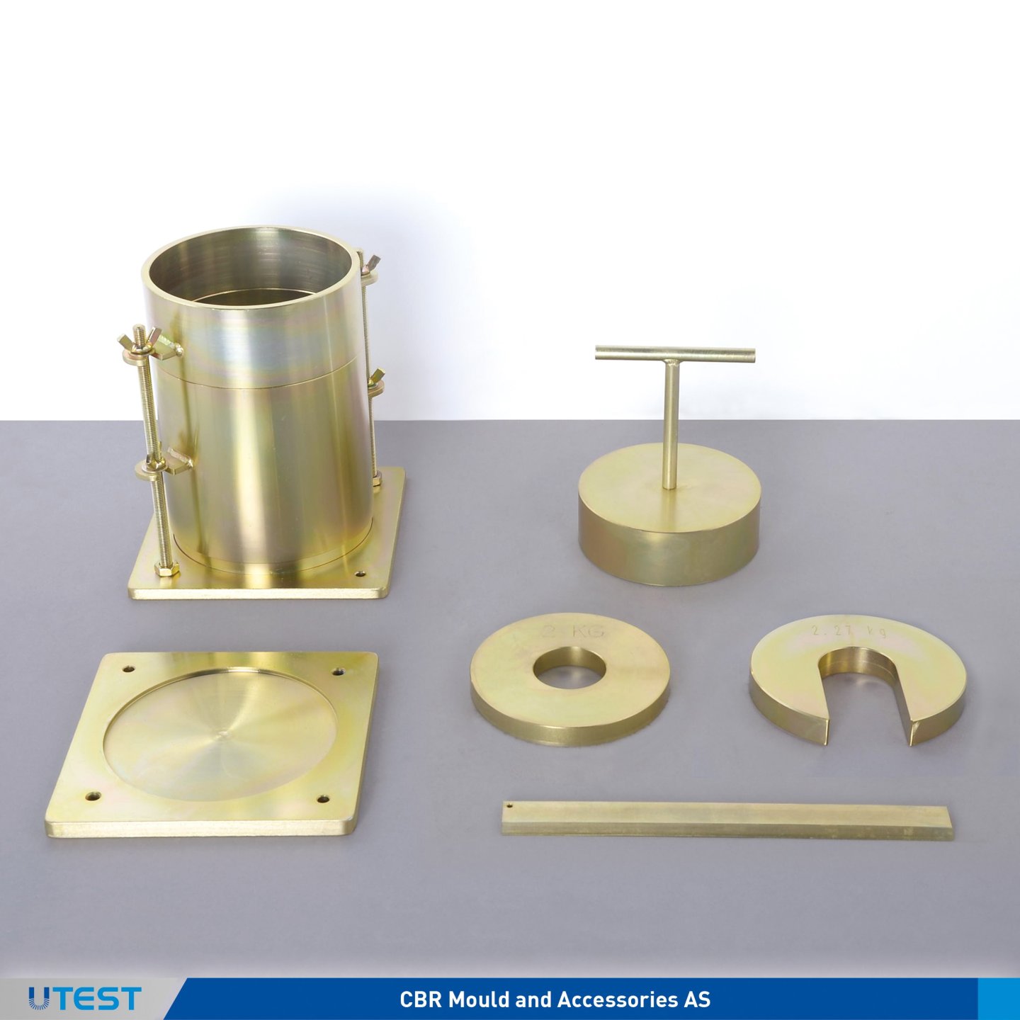
Product Code
CBR Mould and Accessories AS
Standards
AS 1289.6.1.1
Each accessories listed below should be ordered separately.
|
Product Code |
Description |
Dimensions |
Weight (approx.) |
|
UTS-0700AS |
CBR Mould AS. Ø152 mm.Supplied complete with extension collar and perforated base plate |
200x200x240 mm |
8 kg |
|
UTS-0703AS |
Split CBR Mould AS Ø152 mm. Supplied complete with extension collar and perforated base plate |
200x200x240 mm |
8 kg |
|
UTS-0705AS |
Spacer Disc with T handle, NF, Ø150mm, 61 mm height. |
150x150x170 mm |
5 kg |
|
UTS-0708AS |
Annular Surcharge Weight, AS |
150x150x20 mm |
2,25 kg |
|
UTS-0710AS |
Slotted Surcharge Weight, AS |
150x150x20 mm |
2,25 kg |
|
UTS-0717AS |
CBR Soak Weight, AS |
160x160x50 mm |
4,50 kg |
|
UTS-0724E |
Straightedge |
300x30x5 mm |
0,30 kg |
|
UTS-0729 |
Filter papers for CBR test, No:1x Ø152,4 mm (Pack of 100). |
160x160x30 |
0,20 kg |
46. CBR Mould and Accessories NF
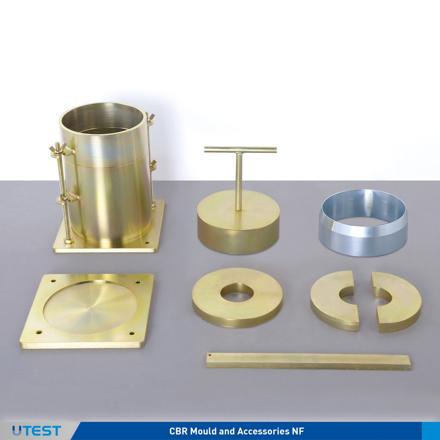
Product Code
CBR Mould and Accessories NF
Standards
NF P 94-078 (Alternative)
Each accessories listed below should be ordered separately.
|
Product Code |
Description |
Dimensions |
Weight (approx.) |
|
UTS-0610NF |
Modified Proctor /CBR Type Mould, NF, Ø152 mm. Supplied complete with extension collar and solid base plate |
160x160x200 mm |
15 kg |
|
UTS-0613NF |
Split Modified Proctor /CBR Type Mould, NF, Ø152 mm.Supplied complete with extension collar and solid base plate |
160x160x200 mm |
15 kg |
|
UTS-0705NF |
Spacer Disc with T handle, NF, Ø151mm, 36 mm height. |
150x150x250 mm |
9 kg |
|
UTS-0708NF |
Annular Surcharge Weight, NF |
150x150x100 mm |
2,30 kg |
|
UTS-0709NF |
Split Surcharge Weight, NF |
150x150x100 mm |
2,30 kg |
|
UTS-0713NF |
CBR Perforated Base Plate NF |
200x200x50 mm |
3 kg |
|
UTS-0724E |
Straightedge |
300x30x5 mm |
0,30 kg |
|
UTS-0725 |
Cutting Collar |
100x100x100 mm |
0,50 kg |
|
UTS-0729 |
Filter papers for CBR test, No:1x Ø152,4 mm (Pack of 100). |
160x160x30 mm |
0,20 kg |
47. Swell Plate for CBR Swelling Test
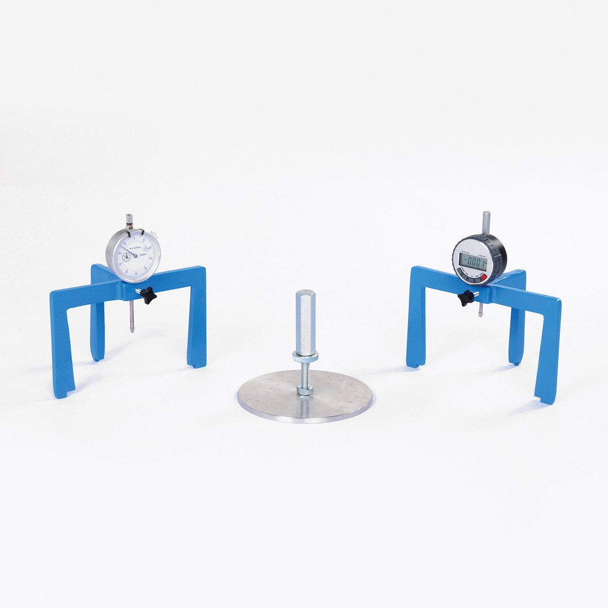
Product Code
|
UTS-0790E.B |
Adjustable Stem and Perforated Aluminum Plate for CBR Swelling Test, EN, BS |
|
UTS-0790A |
Adjustable Stem and Perforated Brass Plate, ASTM, for CBR Swelling Test |
|
UTS-0790NF |
Adjustable Stem and Perforated Plastic Plate, NF, for CBR Swelling Test |
|
UTS-0790AS |
Adjustable Stem and Perforated Plate, AS, for CBR Swelling Test |
|
UTS-0792 |
Tripod for CBR Swelling Test, ASTM, AS, BS, NF, for UTS-0700A, UTS-0700AS, UTS-0610B.E and UTS-0610NF |
|
UTS-0792E |
Tripod for CBR Swelling Test, EN, for UTS-0610E |
|
UTGM-0120 |
Analog Gauge 30 mm travel x 0.01 mm division |
|
UTGM-0148 |
Digital Dial Gauge 25x0,01 mm, LCD Display Data Output |
|
UTGM-0152 |
Digital Dial Gauge 12,7x0,001 mm, LCD Display Data Output |
|
UTS-0794 |
CBR Soaking Tank (6 pcs. CBR Mould Capacity) |
Standards
EN 13286-47; ASTM D1183; BS 1377:4, 1924:2; NF P 94-078; AS 1289.6.1.1
This equipment is used to monitor the swelling by placing it on top of the soil sample. The swell test consists of perforated plate (swell plate) with adjustable stem, dial gauge and dial gauge tripod for mounting swell dial gauge in position on CBR Mould Collar.
UTS-0794 CBR Soaking Tank is supplied complete with a bottom metal grid
The prefered gauge and each other equipment should be ordered separately for swelling test.
|
Product Code |
Dimensions |
Weight |
|
UTS-0790 |
150x150x100 mm |
1 kg |
|
UTS-0790NF |
150x150x120 mm |
0.5 kg |
|
UTS-0792 |
130x190x120 mm |
0.3 kg |
|
UTGM-0120 |
50x60x120 mm |
0.2 kg |
|
UTS-0794 |
500x700x450 mm |
7.7 kg |
48. CBR Test Machine with Load Ring
Product Code
|
UTS-0852 |
CBR Test Machine with Load Ring, 50 kN capacity |
|
Models for 220-240V 50-60 Hz, 1 ph |
UTS-0852 |
|
Models for 110-120V, 60Hz, 1ph |
UTS-0852-N |
Standards
EN 13286-47; BS 1377:4; ASTM D1883; AASHTO T193;
NF P94-078; AS 1289.6.1.1; UNI CNR 10009
The UTS-0852 is designed for performing laboratory evaluation of the CBR value of highway sub bases and subgrade and for the determination of strength of cohesive materials which have maximum particle sizes less than 19 mm (3/4”).
The UTS-0852 is designed to load the penetration piston into the soil sample at a constant rate to measure the applied load and piston penetration at predetermined intervals.
The machine is designed to be mounted on a suitable bench and comprises of a robust and compact two column frame with adjustable upper cross beam. The frame has 50 kN capacity. The test speed is 1.27 mm/min. for ASTM/EN/AASHTO/BS/NF tests. Loading and unloading are down from the front panel by UP/DOWN buttons. Unloading speed is udjusted 5 mm/min for easy re-testing.
The CBR Test Machine is supplied complete with;
- Load Ring, 50 kN
- Digital dial gauge 25 x 0.01 mm (UTGM-0148) with holder (UTS-0853)
- Penetration Piston (UTS-0870)
|
Dimensions |
470x600x1180 mm |
|
Weight (approx.) |
102 kg |
|
Power |
370 W |
49. Automatic CBR Test Machine
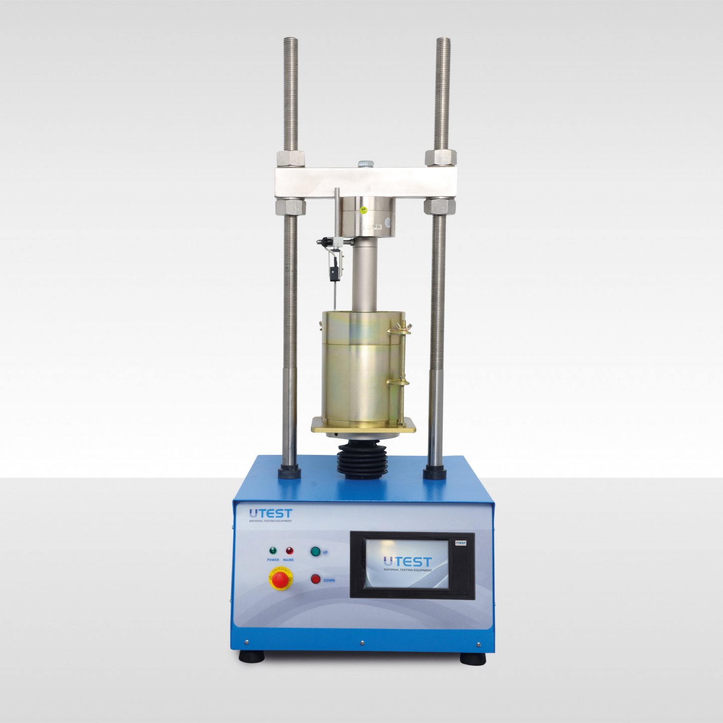
Product Code
|
UTS-0856.ACPR |
Automatic CBR Test Machine with U-Touch PRO Control Unit |
|
Models for 220-240V 50-60 Hz, 1 ph |
UTS-0856.ACPR |
|
Models for 110-120V, 60Hz, 1ph |
UTS-0856.ACPR-N |
Standards
EN 13286-47; BS 1377:4; ASTM D1883; AASHTO T193; NF P94-078; AS 1289.6.1.1; UNI CNR 10009
The UTS-0856.ACPR Automatic CBR Test Machine is designed for performing laboratory evaluation of the CBR value of highway sub-bases and sub-grade, and determination of the strength of cohesive materials which have maximum particle sizes less than 19 mm (3/4”).
The UTS-0856.ACPR is composed of a robust and compact two column frame with adjustable upper crossbeam driven by an electromechanical ram with a maximum capacity of 50 kN and a data acquisition and processing system.
The UTS-0856.ACPR is designed to load the penetration piston into the soil sample at a constant rate to measure the applied load and piston penetration at predetermined intervals. This main feature allows the user to perform tests complying to BS, EN, ASTM or AASHTO standards with the same machine.
Rapid adjustment of the platen is also provided by up and down buttons which are located on the front panel of the machine. The UTS-0856.ACPR is supplied complete with a 50 kN load cell, penetration piston, linear potentiometric displacement transducer (25 mm x 0.001 mm).
U-Touch PRO Control Unit
U-Touch PRO Control Unit is designed to control CBR test machine UTS-0856.ACPR to perform acc. to EN, ASTM/AASHTO and BS standards.
The Unit can perform CBR tests as a stand-alone without the use of a PC or with the USOFT-0856 software and a PC. Control of machine, acquisition of load and displacement data in real time are provided by the unit
The control unit has easy to use menu options. It displays all menu option listings simultaneously, allowing the operator to access the required option in a seemless manner to activate the option or enter a numeric value to set the test parameters and see all the data while the test running.
Control Unit offers many addition unique features. You can save test results in its internal memory and can be controlled remotely from anywhere around the world.
Main Features
- Can make the test with displacement control
- Real time display of test graph.
- 4 analog channels for load cell and displacement sensors
- Can control second frame
- Calibration function for channels.
- Programmable digital gain adjustment for load-cell and potentiometric sensors, voltage and current transmitters
- Closed-loop PID for steady pace rate
- Calculates corrected CBR value at 2.5 and 5 mm the digital unit saves the load value at user defined displacement values such as 0.625, 1.25, 1.875, 2.5, 3.75, 5, 7.5,10, 12.5 mm
- The load corresponds to the displacements corrected respect to the linear region of the data has also saved
- The % CBR at 2.5 mm and % CBR at 5 mm is also automatically calculated and saved
PLEASE see the pages of “General Properties of U-Touch PRO Control Units” for details of the properties of software of the unit.
USOFT-0856 UTEST Software for CBR Test
USOFT-0856 CBR Test Software is developed for EN/ASTM/AASHTO/BS CBR Test. The software includes control of machine, acquisition of load and displacement data, generating and saving reports.
The software prepares a summary result for the user that will only need some specific loads such as at 0.625 mm, 1.25 mm, 2.5 mm and 5 mm.
The software continously updates load, stress and displacement till the end of test. Sofware can automatically draw the best tangent line and perform the upward concave correction as suggested by ASTM D 1883. The corrected stress values are then calculated respect to this offset.
The CBR value at 2.5mm and 5.0mm are calculated by using the standart load values at those penetrations. On the general information tab, by entering necessary information, dry density calculations can be made through the software. The software supports metric, SI and Imperial unit system.
See the pages of “General Properties of Utest USOFT Softwares” for details of the properties of software and hardware.
The CBR Test Machine is supplied complete with;
- Load Cell, 50 kN
- Penetration Piston (UTS-0870)
- Linear potentiometric displacement transducer25 mm x 0.001 mm (UTGM-0062) with holder (UTM-0114)
- Computer Software
- LAN Connection Cable
|
Dimensions |
470x600x1180 mm |
|
Weight (approx.) |
102 kg |
|
Power |
370 W |
50. In-Situ CBR Test Apparatus
Product Code
|
UTS-0865B |
In-situ CBR Test Apparatus |
|
UTS-0866 |
Extension Rod, 1m, for UTS-0865 (Supplied with a nipple) |
|
UTS-0867 |
Conversion Frame |
Standards
BS 1377:9; 1924:2
The UTS-0865B In-situ CBR Test Apparatus, 50 kN capacity,is used for the on-site determination of the bearing capacity of soils used in road construction.
The set consists of:
- 50 kN capacity mechanical jack with ball seating
- 50 kN capacity load ring with an adaptor
- Analog penetration dial gauge (30 mm travel x 0.01 mm) with connection part
- CBR Penetration piston (UTS-0870)
- Set of extension rods (2 pcs. 110 mm, 1 pcs. 300 mm and 1 pcs. 600 mm length) 3 pcs. nipples, a height adjustment bolt and its nut)
- Datum bar assembly with two tripod stands
- 4.5 kg (10lb) annular surcharge weight
- 4.5 kg (10lb) slotted surcharge weight (2 pcs.)
- 9 kg (20lb) slotted surcharge weight (2 pcs.)
- Vehicle bracket
- Wooden carrying case
Wooden Carrying Case
for UTS-0865B
In-situ CBR Test Apparatus, used for the in-situ determination of the bearing capacity of soils.The UTS-0867 Conversion Frame is used to convert the IN-situ CBR test to a mechanical laboratory CBR test machine.
The system is easily assembled onto the conversion frame with the addition of some of the accessories included in UTS-0865. The frame is used with the jack, load ring, CBR mould and penetration piston.
Supplied complete with wooden box. 50 kN load ring, 1m extension rod with nipple (UTS-0866) should be ordered seperately.
|
Product Code |
Dimensions |
Weight (approx.) |
|
UTS-0865B |
300x1700x300 mm (case) |
50 kg |
|
UTS-0867 |
260x370x1150 mm |
22 kg |
51. Sand Replacement Test Sets
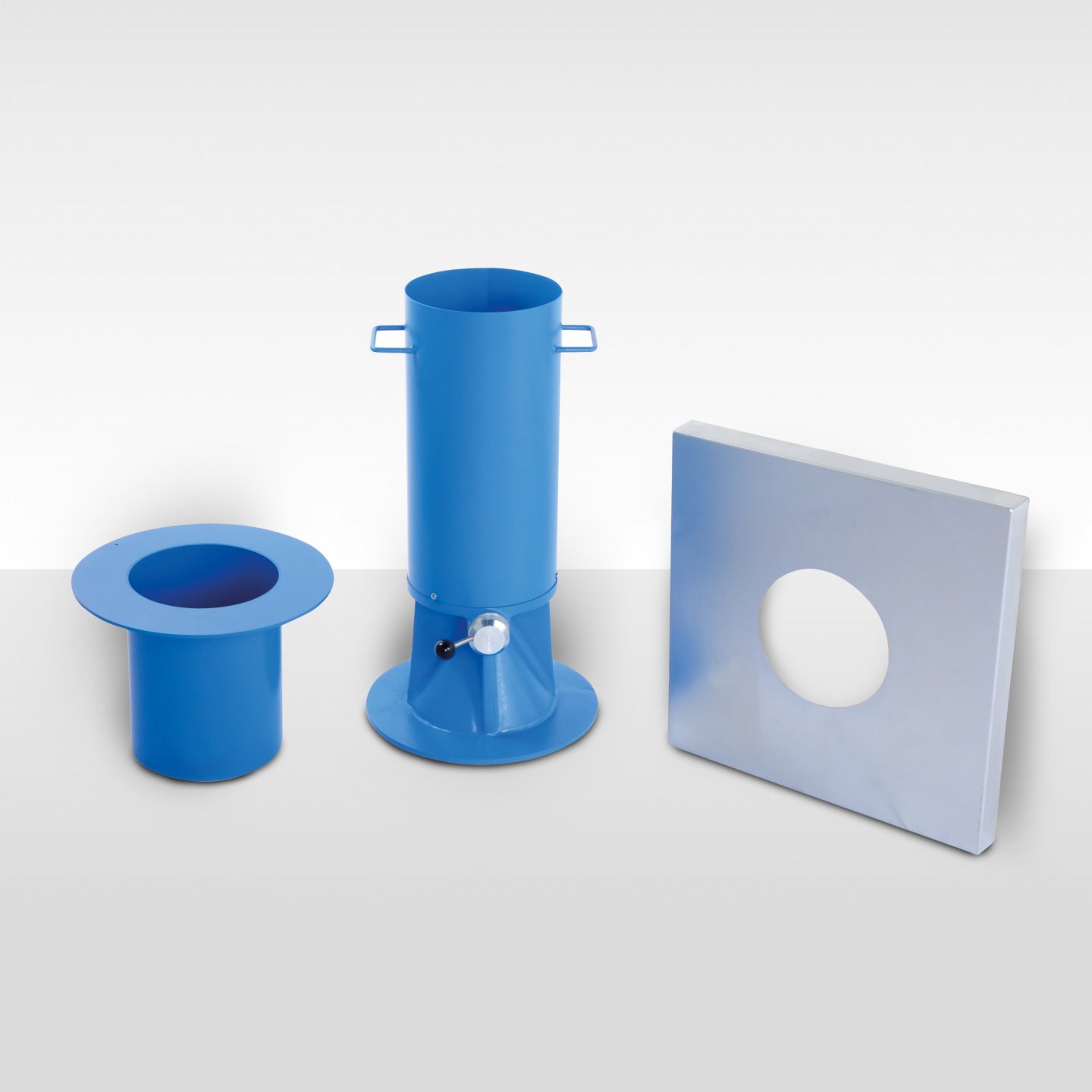
Product Code
|
UTS-0900 |
Sand Replacement Test Set 100 mm BS |
|
UTS-0901 |
Sand Pouring Cylinder 100 mm dia. for UTS-0900 |
|
UTS-0902 |
Calibration Container for UTS-0900 |
|
UTS-0903 |
Metal Tray for UTS-0900 |
|
UTS-0910 |
Sand Replacement Test Set 150 mm BS |
|
UTS-0911 |
Sand Pouring Cylinder 150 mm dia. for UTS-0910 |
|
UTS-0912 |
Calibration Container for UTS-0910 |
|
UTS-0913 |
Metal Tray for UTS-0910 |
|
UTS-0920 |
Sand Replacement Test Set 200 mm BS |
|
UTS-0921 |
Sand Pouring Cylinder 200 mm dia. for UTS-0920 |
|
UTS-0922 |
Calibration Container for UTS-0920 |
|
UTS-0923 |
Metal Tray for UTS-0920 |
Standards
BS 1377:9, 1924:2
The Sand Replacement Test Set is used for the determination of the degree of compaction on site. The Complete set consists of a pouring cylinder, calibration container and tray. The sand pouring cylinder is made of cast aluminum and precisely machined; the calibration container and tray are made of plated sheet steel. The test set is available in three different sizes.
|
Product Code |
Dimensions |
Weight (approx.) |
|
UTS-0900 |
300x300x440 mm |
8 kg |
|
UTS-0910 |
280x300x570 mm |
15 kg |
|
UTS-0920 |
360x360x660 mm |
28 kg |
52. Sand Cone Sets
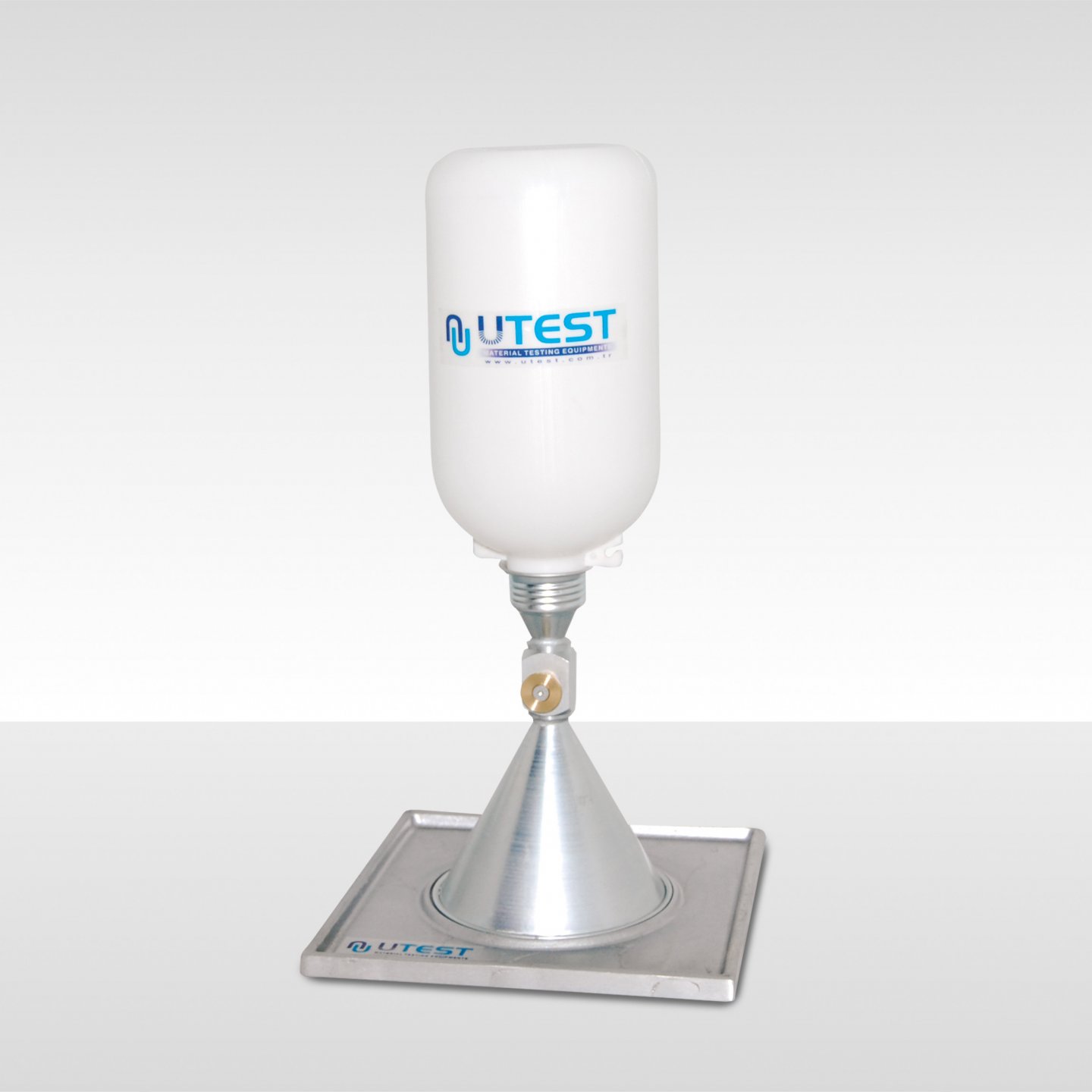
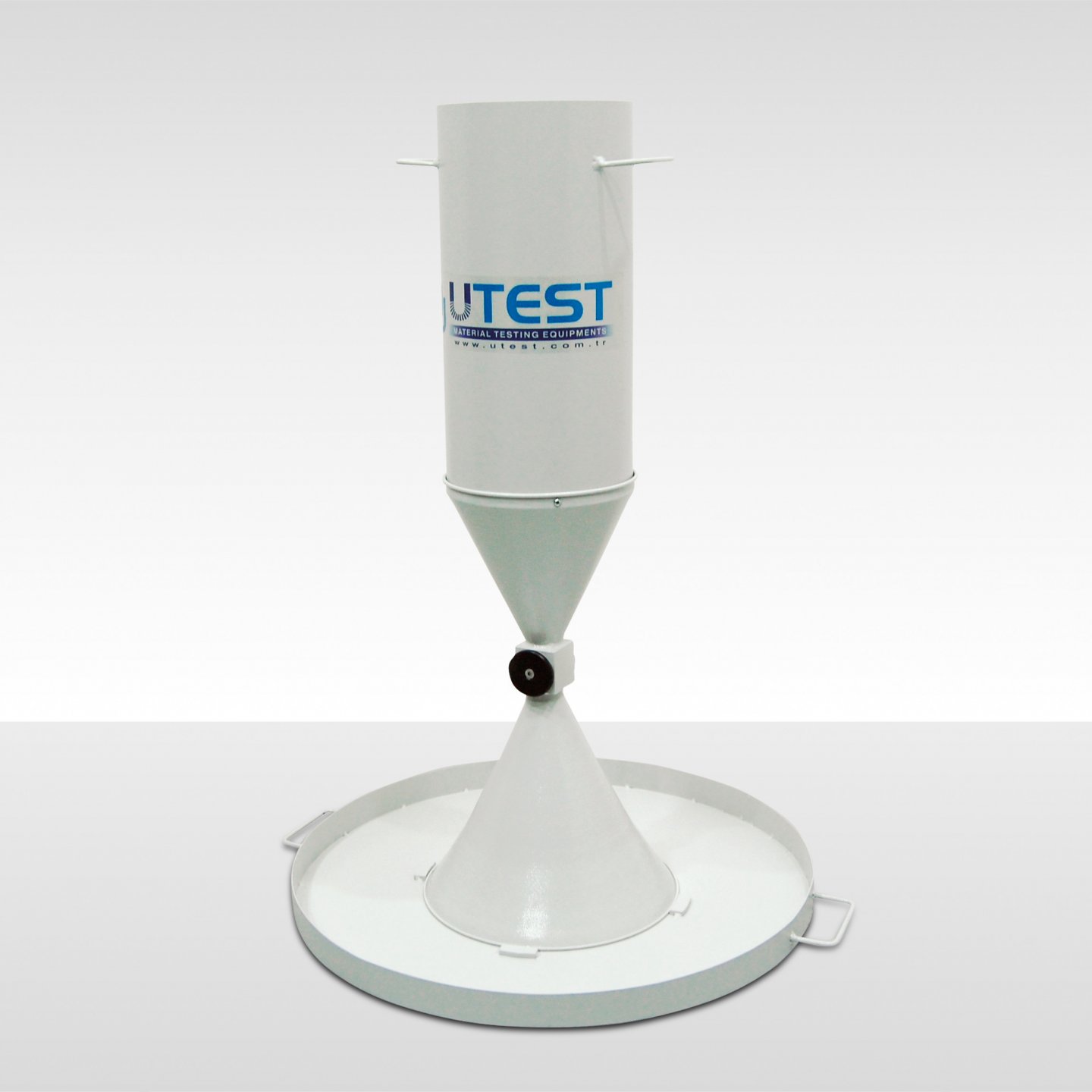
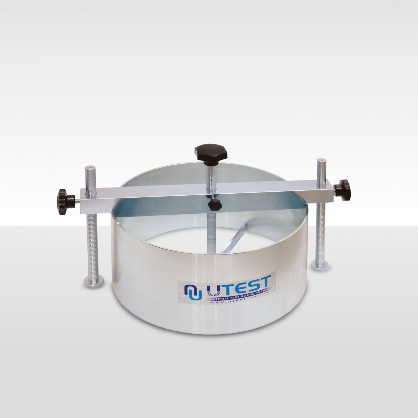
Product Code
|
UTS-0950 |
Sand Cone Set 6.5" |
|
UTS-0960 |
Sand Cone Set 12" |
|
UTS-0952 |
Plastic Sand Jar 5 L, for UTS-0950 |
|
UTS-0954 |
Calibration Container for UTS-0950 |
|
UTS-0962 |
Density Cylinder, 12" |
Standards
ASTM D1556; AASHTO T181, T191
The UTS-0950 and UTS-0960 Sand Cone Sets are used for the determination of the degree of compaction on site. UTS-0950 includes double cone, plastic sand jar and base plate with flanged hole.Calibration container should be ordered seperately.
UTS-0962 Density Cylinder is used for determining in place density of compacted base courses containing large sizes of coarse aggregates. Density cylinder should be ordered seperately.
|
Product Code |
Dimensions |
Weight (approx.) |
|
UTS-0950 |
350x350x200 mm |
3 kg |
|
UTS-0960 |
310x310x600 mm |
10 kg |
|
UTS-0962 |
550x400x350 mm |
10 kg |
53. Surface Soil Samplers
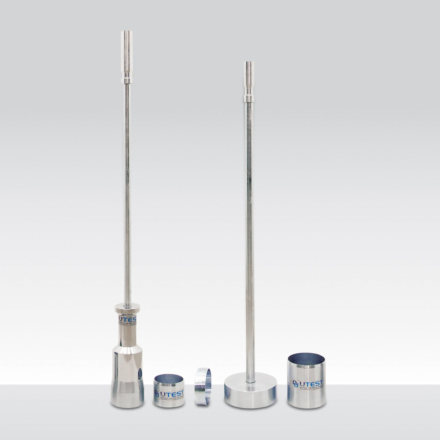
Product Code
|
UTS-0965 |
Surface Soil Sampler (Core Cutter), 3” dia. ASTM |
|
UTS-0966 |
Spare Sampling Tube (Drive Cylinder), 3” (76.2 mm) x 70 mm high, ASTM, for UTS-0965 |
|
UTS-0967 |
Surface Soil Sampler (Core Cutter), 4” dia. ASTM |
|
UTS-0968 |
Spare Sampling Tube (Drive Cylinder), 4” (101.6 mm) x 127 mm high, ASTM, for UTS-0967 |
|
UTS-0970 |
Surface Soil Sampler (Core Cutter) Set, 100 mm dia., BS |
|
UTS-0975 |
Surface Soil Sampler (Core Cutter) Set, 150 mm dia., BS |
Standards
ASTM D2937; CNR No.22; BS 1377:9
Surface Soil Sampler (Core Cutter) is used to determine the insitu density of soil by taking a standard volume of soil sample from the ground which is then removed, trimmed and weighed.
The ASTM/CNR version, UTS-0965 and UTS-0967 Surface Soil Sampler (Core Cutter) consists of a drive head, 5 kg drive hammer and a thin wall sampling tube. 5 kg sliding weight drop hammer makes a free-fall on to the driving head which is placed on top of the sampling tube. Manufactured from steel and plated for corrosion resistance.
UTS-0970 BS Type 100 mm Surface Soil Sampler (Core Cutter) Set consists of a driving dolly, 13,5 kg driving rammer and 100 mm dia. x 130 mm high core cutter. UTS-0975 BS Type 150 mm Surface Soil Sampler (Core Cutter) Set BS consits of a driving dolly, 16 kg driving rammer and 150 mm diax 180 mm high core cutter.
|
Product Code |
Dimensions |
Weight (approx.) |
|
UTS-0965 |
70x70x1100 mm |
6 kg |
|
UTS-0966 |
70x70x80 mm |
0,30 kg |
|
UTS-0967 |
110x110x1100 mm |
9 kg |
|
UTS-0968 |
110x110x110 mm |
0,50 kg |
|
UTS-0970 |
100x100x1000 mm |
15 kg |
|
UTS-0975 |
150x150x1000 mm |
18 kg |
54. Balloon Density Apparatus
Product Code
|
UTS-0990A |
Balloon Density Apparatus 1600 ml ASTM |
|
UTS-0993NF |
Balloon Density Apparatus 3000 ml NF |
|
UTS-0996NF |
Balloon Density Apparatus 6000 ml, NF |
|
UTS-1000NF |
Balloon Density Apparatus NF, 10000 ml, NF |
Standards
ASTM D2167; NF P94-061-2: AASHTO T205
Balloon Density Apparatus are used for the on-site determination of the density of well bonded soil according to the ASTM and French standards respectively.
UTS-0990A consists of a graduated cylinder of 1596 ml capacity housed inside an aluminium guard, a reversible rubber aspirator pump, a density plate 9 inches square, and 12 rubber balloons. The principle of operation is similar to the sand replacement but the hole is filled by a rubber balloon where water is pumped. The amount of water can be easily determined by the graduation of the cylinder.
According to NF standard, a metal cylinder is filled with water which is then pumped into a rubber membrane mounted on the base of the cylinder. The water pressure is controlled by a pressure gauge and the volume of the balloon is measured on the graduated piston stem.
NF Type Balloon Density Apparatus are supplied complete with complete with;
• Reinforced Membranes, 6 pcs./pack
• Base Plate
• Locking Clamps, 4 pcs. (6 pcs. for UTS-1000NF)
ASTM Type Balloon Density Apparatus is supplied complete with complete with;
• A graduated cylinder, 1596 mL capacity housed inside an aluminum guard,
• A reversible rubber aspirator pump,
• Density plate,
• Rubber balloons, 12pcs.
|
Product Code |
Dimensions |
Weight (approx.) |
|
UTS-0990A |
320x320x650 mm |
7 kg |
|
UTS-0992NF |
320x320x650 mm |
7 kg |
|
UTS-0996NF |
450x450x860 mm |
12 kg |
|
UTS-1000NF |
350x350x820 mm |
25 kg |
55. Non-Nuclear Soil Density Gauge
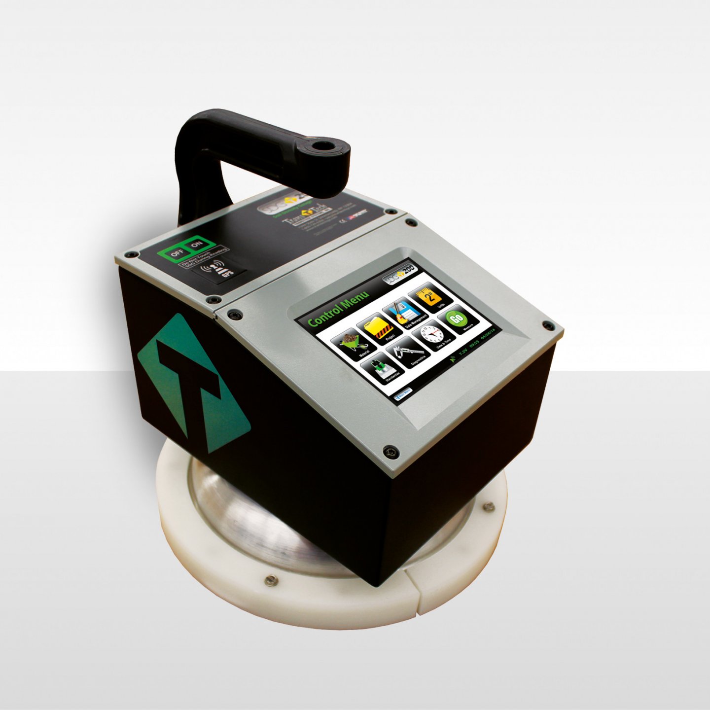
Product Code
UTS -1060 Non-Nuclear Soil Density Gauge
Standards
ASTM D 7830
Non-Nuclear Soil Density Gauge is used for detecting density of Soil specimens with non nuclear type. UTS-1280 is fully equipped with a touch screen and user friendly graphical menu interface, running Microsoft Windows silently in the backround for flowless operation, easy software are upgrades and enchanced user support.
The instruments general specifications are;
- Full colour graphics driven interface, 480 x 640 VGA touch screen display with LED backlight for easy visibility.
- Displays GPS status, available battery voltage, low battery and date/time,
- Rugged case design made from aluminum, powder-coated gloss black with orange reflective vinyl graphics increasing driver awareness to road workers at night
- Data Management Feature, quickly access, can be downloaded and deleted project data,
- Required files can be downloaded to UTS-1280 via. USB,
- Fast, reliable, accurate, and repeatable in real time, User Friendly, in-process, cost effective tool for any user,
- The most inpoftant point is; Non-Nuclear means no Badges or Lisances and no storage or transport concerns.
Operational Features
- Display: Full color graphics driven user interface, 480x640 VGA touch screen display with LED backlight for easy visibility in daylight or dark situations.
- Status Bar: Displays GPS status, Data Save status, battery voltage, low battery and date and time
- Project Details: Stores up to 20 projects with details,
- Material Details: Stores up to 20 materials, details include Material
- Name, Description, Max Dry Density, Opt. Moisture, Dry Density Offset,
- % Moisture Offset, % Greater than 3", % Greater than 3/4", % Gravel,
- % Sand, % Fines, PL, LL, Cu and Cc
- Data Logging: Ability to store all measurements
- Reports: Easily download data to be imported into Excel
- GPS Control: When activated will display latitude and longitude positions, number of satellites the gauge is connected to as well as the UTC date and time, also available in UTM format. GPS information will store with each measurement when Data Save and GPS feature is enabled, (Status Bar Icon)
- Update Software: One touch upload of new software using a USB memory stick
- Data Management: Quickly access, download or delete your project data
- Set Time & Date: Quick time and date setup, MM/DD/YY and DD/MM/YY formats
- Units: Interchangeable settings for Density (kq/rn3, Ib/ft3), Temp (°C,°F)
- Standardization: While gauge is still in the case, a quick one touch measurement will insure the gauge is still in proper working mode
- Calculator: Built in four function calculator
- Enhanced Customer Support: Diagnostic screen to aid in factory support
- User Programmable Target Density: Used for calculating % compaction
Operational Specification
|
Measurement Mode |
|
|
• Average |
Averages five (5) readings and stores data including location date and time. Stores thousands of records |
|
• Continuous |
Instantaneous density readings. |
|
Function Mode |
|
|
• Wet & Dry Density, % Compaction, % Moisture |
|
|
Soil Specification |
|
|
• Designed to operate with standard soils used in civil construction projects. |
|
|
• Requires inputs from standard |
- Standard Test Methods for Liquid Limit, Plastic Limit and |
|
-Plasticity Index of Soils (ASTM D4318) |
|
|
- Particle Size Distribution (ASTM D422) |
|
|
- Proctor Test (ASTM D698 and D1557) |
|
Mechanical Specification
|
• Unit Weight |
14.2 lbs (6.44kg) |
|
• Unit Dimensions |
11"x11"x12" High (27,9 cm x 27,9 cm x 30,4 cm) with handle extension 29" High (73,6 cm) |
|
• Shipping Weight w/ Case |
42,5 lbs (19,27 kg) |
|
• Shipping Dimensions |
24" x 19,5" x 14" (60,9 cm x 49,5 cm x 35,5 cm) |
Measurement Specification
|
• Sensing Area |
11 in. (27.9mm) dia. base allows optimum measurement on fine and coarse material types |
|
• Measurement Depth |
Designed for use on a standard 12" (30cm) un-compacted layer of soil during or after compaction. |
|
• Measurement Display |
Dry Density, % Compaction, % Moisture, GPSData, Material Information and Project Name |
Electrical Specification
|
• Microprocessor Controlled |
|
|
• CE Mark |
Complies with EN 61000-4-2, 61000-4-3, 61000-4-8 |
|
• Battery |
14.0 Amp-hr NiMH, 7.2 V |
|
• Recharge Time |
4 hours |
|
• Battery Charger |
Self Contained CE & UL Certified Universal AC Charger, DC Charger |
|
• Computer Ports |
1 USB Port |
56. RoadReader Nuclear Density Gauges
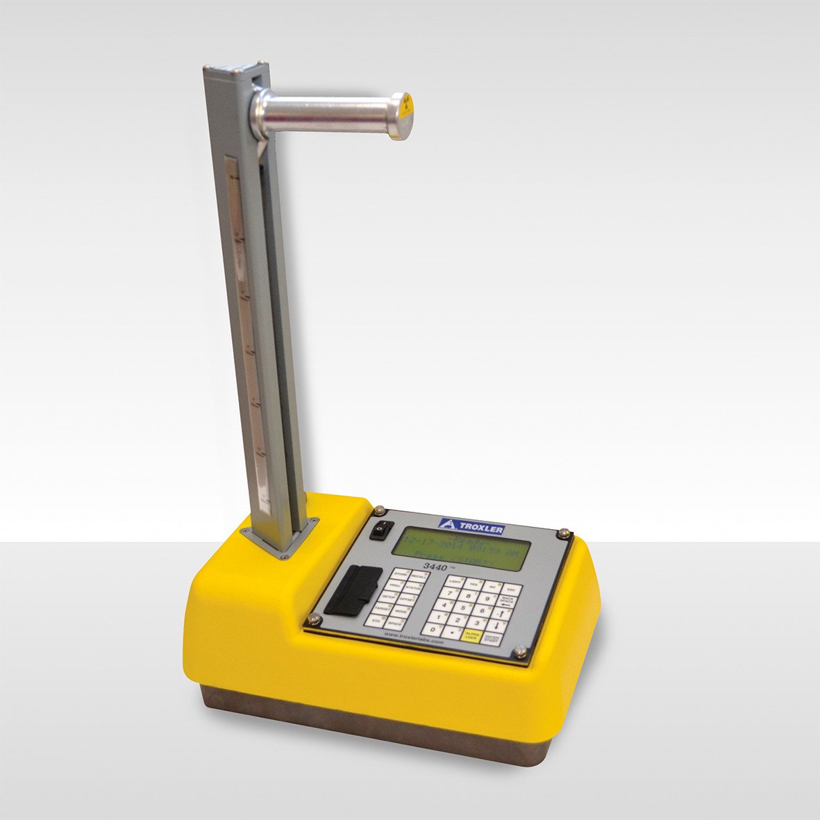
Product Code
UTS-1050 RoadReader Nuclear Density Gauges Model 3440P
Standards
ASTM D 2950, C 1040, D 6938
The Troxler RoadReader nuclear moisture / density gauges are used by many contractors, engineers and highway departments for compaction control of soil, aggregate, concrete and full asphalt. The ASTM standarts numbers D 2922, D 3017, D 2950 and C 1040 are met or exceeded by these gauges. Two test models are avaliable for density determination: Direct transmission and Backscatter. The operator selects the mode depending on the material type and thickness of the layer being tested. The model 3430 is avaliable with keypad, display and operator’s manual in languages and is the siplest most economical gauge offered by Troxler. The Model 3440 provides 30 special functions, storage of up to 1000 test records, an 18-month warranty and many more options that make it simple to operate and a necessity for all technicians.
Three Test Modes
BACKSCATTER
Backscatter is rapid and nondestructive. The gamma source and detectors remain inside the gauge which rests on the surface of the test material. Gamma rays enter the test material and those scattered through the material and reaching the detectors are counted. Backscatter is primarily used to determine density on layers of asphalt and concrete approximately 4" thick.
DIRECT TRANSMISSION
The gamma source is positioned at a specific depth within the test material by insertion into an access hole. Gamma rays are transmitted through the test material to detectors located within the gauge. The average density between the gamma source and the detectors is then determined. Erros resulting from surface roughness and chemical composition of the test material are greatly reduced and aguge accuracy is improved. Direct transmission is used for testing lifts of soil, aggreaget, asphalts and concrete up to 12" depth.
MOISTURE DETECTION
The moisture measurement is nondestructive with the neutron source and detector located inside the gauge just above the surface of the test material. Fast neutrons enter the test material and are slowed after colliding with the hydrogen atoms present. The helium 3 detector in the gauge counts the number of thermalized (slowed) neutrons which relates directly to the amount of moisture in the sample.
Both Models Offer
- Direct readout of wet density, dry density, moisture, %moisture, %voids and %compaction.
- Lightweight
- Powered by rechargeable nicad batteries or backup alkaline batteries
- Prompts user through steps of operation
- Software allows for moisture, density and trench offsets
3440 Features
- Data storage- stores up to 1000 complete test records which canbe downloaded to a printer or computer.
- Extended storage-gauge allows notes to be stored with test record.
- Automatic indexing-eliminates a major source of operator error by automatically sensing depth of measurement.
- 30 special functions provided-self test and service programs, selected precision and field calibration for special materials.
- Calculator mode with storage.
- Nomograph method for measurement of asphalt overlays.
|
Measurement (U.S. Customary Units) |
|||
|
Direct Transmission Density (6") Pcf=lb/ft3 |
15 sec. |
1 min. |
4 min. |
|
Precision at 120 pcf |
±0.42 pcf |
±0.21 pcf |
±0.11 pcf |
|
Composition error at 120 pcf |
±1.25 pcf |
±1.25 pcf |
±1.25 pcf |
|
Surface error (0.05", 100% Void) |
-1.1 pcf |
-1.1 pcf |
-1.1 pcf |
|
Backscatter (98%) (4") |
15 sec. |
1 min. |
4 min. |
|
Precision at 120 pcf |
±1.00 pcf |
±0.50 pcf |
±0.25 pcf |
|
Composition error at 120 pcf |
±2.50 pcf |
±2.50 pcf |
±2.50 pcf |
|
Surface error (0.05", 100% Void) |
-4.7 pcf |
-4.7 pcf |
-4.7 pcf |
|
Moisture at 15 pcf |
15 sec. |
1 min. |
4 min. |
|
Precision at 15 pcf |
±0.64 pcf |
±0.32 pcf |
±0.16 pcf |
|
Surface error (0.05", 100% Void) Depth of measurement @ 15 pcf (8.45") |
-1.12 pcf |
-1.12 pcf |
-1.12 pcf |
|
|
|||
|
Measurement (S.I. Units) |
|||
|
Direct Transmission Density-150mm |
15 sec. |
1 min. |
4 min. |
|
Precision at 2000 kg/m3 |
±6.8 kg/m3 |
±3.4 kg/m3 |
±1.7 kg/m3 |
|
Composition error at 2000 kg/m3 |
±20.0 kg/m3 |
±20.0 kg/m3 |
±20.0 kg/m3 |
|
Surface error (1.25mm, 100% Void) |
-17.0 kg/m3 |
-17.0 kg/m3 |
-17.0 kg/m3 |
|
Backscatter (98%) (100mm) |
15 sec. |
1 min. |
4 min. |
|
Precision at 2000 kg/m3 |
±16.0 kg/m3 |
±8.0 kg/m3 |
±4.0 kg/m3 |
|
Composition error at 2000 kg/m3 |
±40.0 kg/m3 |
±40.0 kg/m3 |
±40.0 kg/m3 |
|
Surface error (1.25mm, 100% Void) |
-75.0 kg/m3 |
-75.0 kg/m3 |
-75.0 kg/m3 |
|
Moisture |
15 sec. |
1 min. |
4 min. |
|
Precision at 250 kg/m3 |
±10.3 kg/m3 |
±5.1 kg/m3 |
±2.6 kg/m3 |
|
Surface error (1.25mm, 100% Void) Meas. Depth @ 250 kg/m3 - 212.5mm |
-18.0 kg/m3 |
-18.0 kg/m3 |
-18.0 kg/m3
|
|
Radiological |
|
|
Gamma Source |
8 mCi ±10% Cs-137 |
|
Neutron Source |
0.060 mCi ±10% Cf-252 or 40 mCi ±10% Am-241:Be |
|
Source Housing |
Stainless Steel Encapsulation |
|
Shielding |
Tungsten, lead and cadmium |
|
Surface Dose Rates |
19 mrem/hr max., neutron and gamma |
|
Source Rod Material |
Stainless Steel |
|
Shipping Case |
DOT 7A, Type A Yellow label II, Tl=0.3 |
|
Mechanical |
|
|
Case |
High Impact Plastic 75L x 35W x 42 T in. |
|
Vibration Test |
0.1 in. (2.5 mm) @ 12.5 hz |
|
Drop Test |
300 mm on 25 mm diameter steel ball |
|
Operating Temp: |
Ambient: 14 to 158°F (-10 to 70°C) Surface: 350°F (175°C) |
|
Storage Temp. |
-70 to 185°F (-55 to 85°C) |
|
Weight |
29 lbs. (13.2 kg) |
|
Shipping Weight |
90 lbs. (40.8 kgs) w/case |
|
Available Models |
8" or 12" index rod with 1" or 2" increments (200 or 300 mm index rod with 25 or 50 mm increments) |
|
Electrical |
|
|
Time Accuracy and Stability |
0.005%, 0.0002% / °C |
|
Power Supply Stability |
0.01% / °C |
|
Stored Power |
30 watt hours |
|
Battery Recharge Time |
14-16 hours (automatic cutoff) |
|
Charger |
110/220 V ac, 50-60 Hz or 12-14 V dc |
|
Readout |
2 x 16 alpha-numeric liquid crystal display |
|
Notes |
|
Gauge returns to Gauge Ready (power saving mode) after two minutes of inactivity, except in standard, stat test, drift test, and in nomograph programs when a 30-minute delay is provided. After 5 hours of inactivity, gauge performs complete power shut-down.
Battery packs are fully protected against overcharge and overdischarge. Emergency Use - Capable of operation with D size alkaline batteries. |
57. Plate Loading Test Set
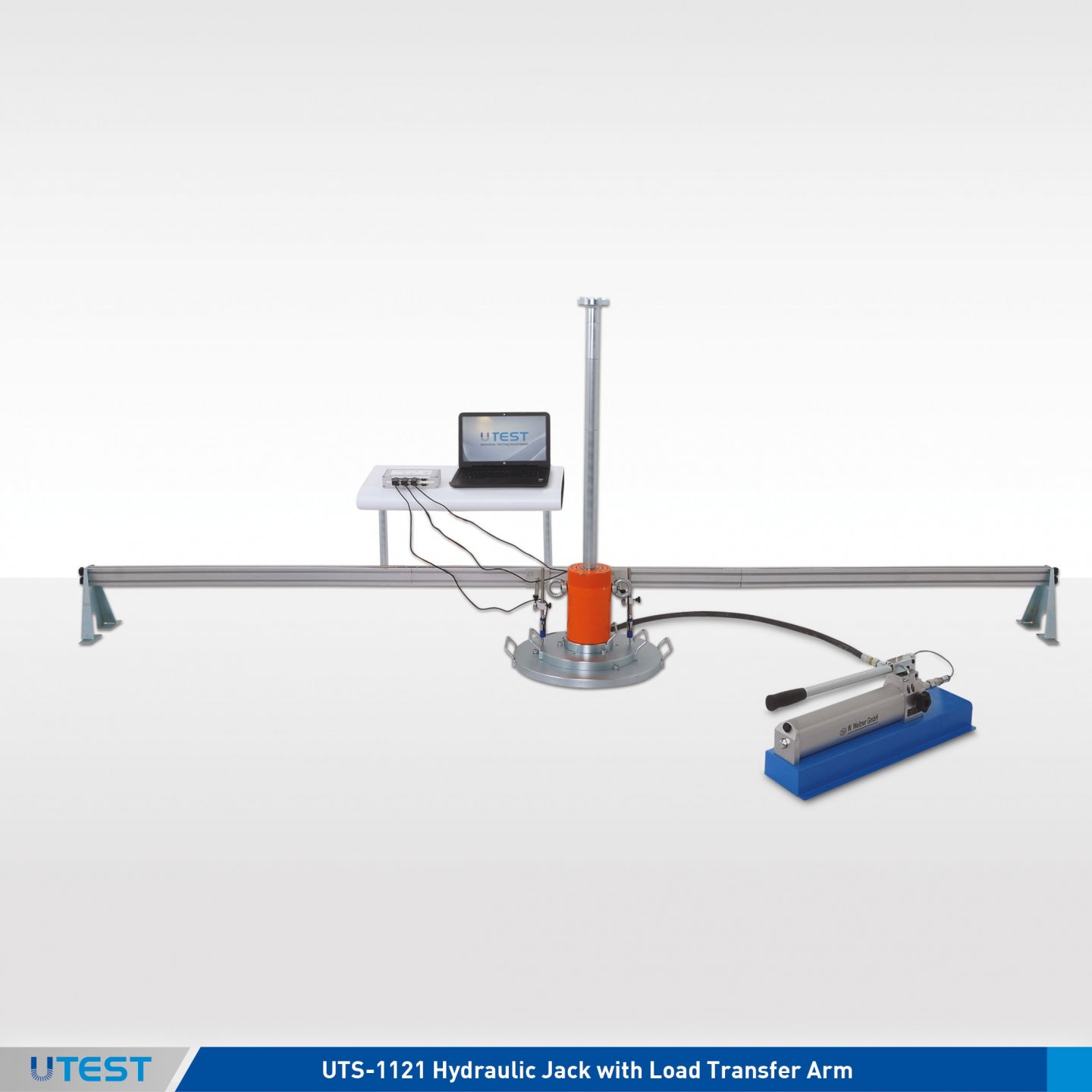
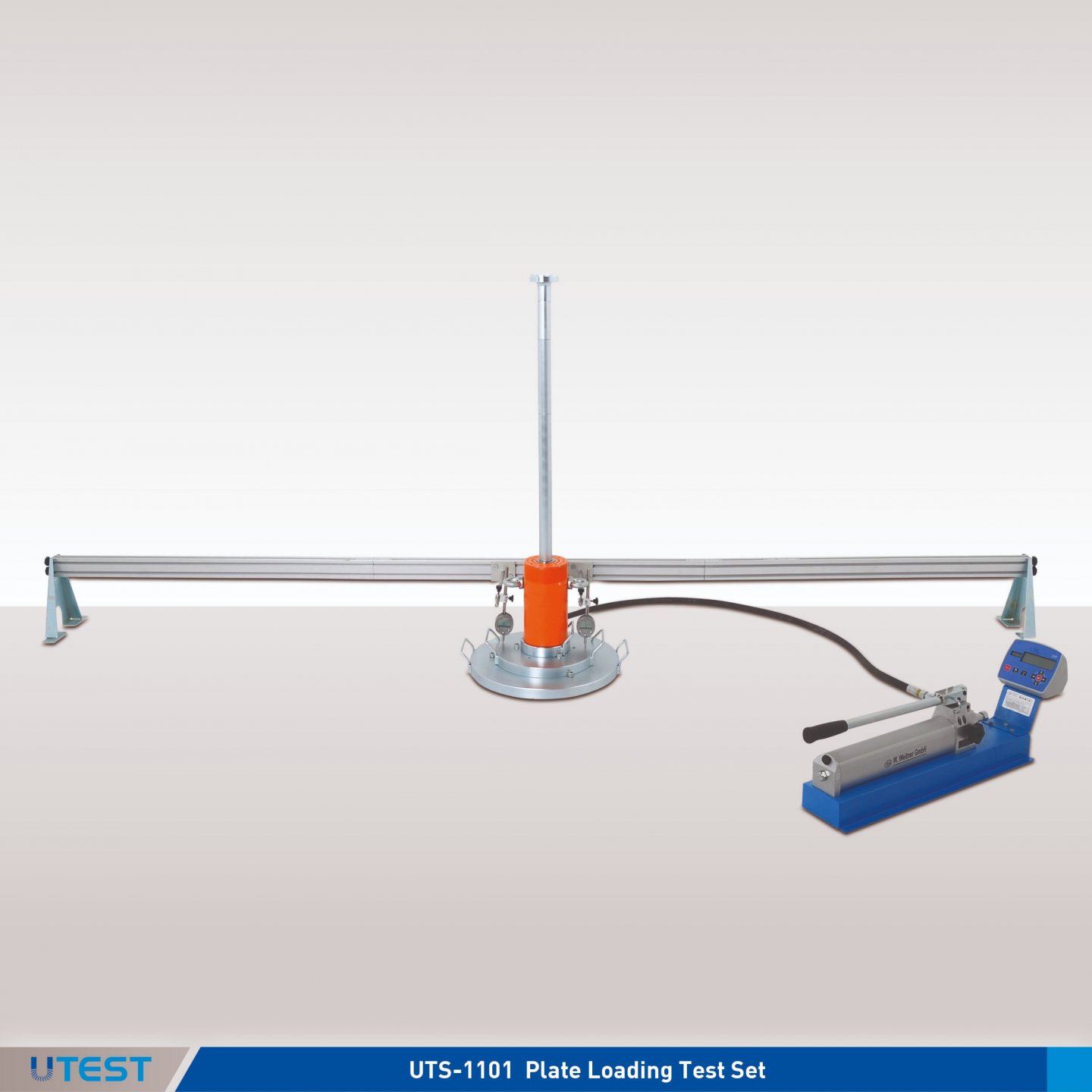
Product Code
|
UTS-1101 |
100 kN (22 500 lbf) Plate Loading Digital Test Set |
|
UTS-1102 |
200 kN (45000 lbf) Plate Loading Digital Test Set |
|
UTS-1105 |
500 kN (112400 lbf) Plate Loading Digital Test Set |
|
UTS-1108 |
Digital Deflection Measurement Assembly for Plate Loading Test Sets |
|
UTS-1109 |
Additional Bar to extend total length up to 5.5 meters |
|
UTS-1111 |
100 kN (22500 lbf) Plate Loading Test Set with Displacement Transducers and Data Logger |
|
UTS-1112 |
200 kN (45000 lbf) Plate Loading Test Set, with Displacement Transducers and Data Logger |
|
UTS-1115 |
500 kN (112400 lbf) Plate Loading Test Set, with Displacement Transducers and Data Logger |
|
UTS-1118 |
Electronic Deflection Measurement Assembly for Plate Loading Test Set |
|
UTS-1133 |
Loading Plate, Ø152 mm (6”), for Plate Loading Test |
|
UTS-1134 |
Loading Plate, Ø160 mm (6,3”), for Plate Loading Test |
|
UTS-1135 |
Loading Plate, Ø10”(254 mm, for Plate Loading Test |
|
UTS-1136 |
Loading Plate, Ø305 mm, (12”) for Plate Loading Test |
|
UTS-1137 |
Loading Plate Ø 457 mm (18”) for Plate Loading Test |
|
UTS-1138 |
Loading Plate Ø 610 mm (24”) for Plate Loading Test |
|
UTS-1139 |
Loading Plate Ø 762 mm (30”) for Plate Loading Test |
|
UTS-1140 |
Additional Plates Set for Plate Loading Test, ASTM (Ø457 mm/18”, Ø610 mm/24” and Ø762mm/30” plates) |
|
UTGE-3810 |
700 bar Manual (Hand Operated) Pressure Equipment |
|
UTGE-3811 |
600 bar Manual (Hand Operated) Pressure Equipment |
Standards
ASTM D1195, D1196; BS 1377:9
Plate load test sets can be used to determine the ultimate bearing capacity of subgrade soils and compacted pavement components. Plate load tests provide data for use in the evaluation and design of rigid and flexible-type airport and highway pavements.
The test is performed by pressing a steel bearing plate into the layer to be measured by the help of a hydraulic jack and measuring the resulting deformation taking place on the layer. This deformation value can also be used to obtain modulus of subgrade reaction which can be correlated to resilient modulus as proposed by “1993 AASHTO Guide for Design of Pavement Structures”
Utest provides two models, one digital and one electronic for plate load testing sets. Both models have 3 different capacities: 100 kN (22 500 lbf), 200 kN (45 000 lbf) and 500 kN (112400 lbf)
All test set supplied with a wooden carrying case.
UTS-1109 Additional Bar to extend total length up to 5.5 meters of measuring bar of plate loading test sets should be ordered.
And also, UTS-1140 Additional Plate Set for 500 kN Plate Loading Test (UTS-1105 or UTS-1115) should be ordered. UTS-1140 which packed in a separate wooden box consists of Ø457mm/18”; Ø610mm/24" and Ø762mm/30" plates.
Detail of UTS-1102 Detail of UTS-1112
|
Product Code |
Capacity |
Automatic Data Logging and PC Software Support |
Load Plates Included |
|
UTS-1101 |
100 kN Plate Loading Digital Test Set |
100 kN Hydraulic Equipment with Fittings ( UTS-1121) |
100 kN hydraulic cylinder, 3 pcs. extension rods with different length |
|
UTGE-3810 700 Bar Manual (Hand Operated) Pressure Equipment. |
|||
|
Ø152mm(6") and Ø305mm(12") loading plates |
|||
|
Digital Deflection Measurement Assembly (UTS-1108) |
2,5 m (8,2 ft) measuring bar with base supports,. plump, spirit level |
||
|
3 pcs. 25 x 0.01mm digital dial gauges (UTGM-0148) with dial supports, |
|||
|
UTS-1102 |
200 kN Plate Loading Digital Test Set. |
200 kN Hydraulic Equipment with Fittings ( UTS-1122) |
200 kN hydraulic cylinder, 3 pcs. extension rods with different length |
|
UTGE-3810 700 Bar Manual (Hand Operated) Pressure Equipment. |
|||
|
Ø152mm(6") and Ø305mm(12") loading plates |
|||
|
Digital Deflection Measurement Assembly (UTS-1108) |
2,5 m (8,2 ft) measuring bar with base supports,. plump, spirit level |
||
|
3pcs. 25 x 0.01mm digital dial gauges (UTGM-0148)with dial supports |
|||
|
UTS-1105 |
500 kN Plate Loading Digital Test Set. |
500 kN Hydraulic Equipment with Fittings ( UTS-1125) |
500 kN hydraulic cylinder, 3 pcs. extension rods with different length |
|
UTGE-3810 700 Bar Manual (Hand Operated) Pressure Equipment. |
|||
|
Ø152mm(6") and Ø305mm(12") loading plates |
|||
|
Digital Deflection Measurement Assembly (UTS-1108) |
2,5 m (8,2 ft) measuring bar with base supports,. plump, spirit level |
||
|
3pcs. 25 x 0.01mm digital dial gauges (UTGM-0148) (UTB with dial supports |
|||
|
UTS-1111 |
100 kN Plate Loading Electronic Test Set. |
100 kN Hydraulic Equipment with Fittings (UTS-1127) |
100 kN hydraulic cylinder, 3 pcs. extension rods with different length |
|
UTGE-3811 600 Bar Manual (Hand Operated) Pressure Equipment. |
|||
|
Ø152mm(6") and Ø305mm(12") loading plates |
|||
|
Electronic Deflection Measurement Assembly (UTS-1118) |
2,5 m (8,2 ft) measuring bar with base supports,. plump, spirit level |
||
|
3pcs. 25 x 0.001mm linear potentiometric displacement transducers and their supports |
|||
|
Interface unit with 4 channel for data acquisition (UTCU-0020), converter DC 12 V to DC 24V and UTEST software.PC is not included and have to be ordered separately |
|||
|
UTS-1112 |
200 kN Plate Loading Electronic Test Set. |
200 kN Hydraulic Equipment with Fittings (UTS-1128) |
200 kN hydraulic cylinder, 3 pcs. extension rods with different length |
|
UUTGE-3811 600 Bar Manual (Hand Operated) Pressure Equipment. |
|||
|
Ø152mm(6") and Ø305mm(12") loading plates |
|||
|
Electronic Deflection Measurement Assembly (UTS-1118) |
2,5 m (8,2 ft) measuring bar with base supports,. plump, spirit level |
||
|
3pcs. 25 x 0.001mm linear potentiometric displacement transducers and their supports |
|||
|
Interface unit with 4 channel for data acquisition (UTCU-0020), converter DC 12 V to DC 24V and UTEST software.PC is not included and have to be ordered separately |
|||
|
UTS-1115 |
500 kN Plate Loading Electronic Test Set. |
500 kN Hydraulic Equipment with Fittings ( UTS-1129) |
500 kN hydraulic cylinder, 3 pcs. extension rods with different length |
|
UTGE-3811 600 Bar Manual (Hand Operated) Pressure Equipment. |
|||
|
Ø152mm(6") and Ø305mm(12") loading plates |
|||
|
Electronic Deflection Measurement Assembly (UTS-1118) |
2,5 m (8,2 ft) measuring bar with base supports,. plump, spirit level |
||
|
3pcs. 25 x 0.001mm linear potentiometric displacement transducers and their supports |
|||
|
Interface unit with 4 channel for data acquisition (UTCU-0020), converter DC 12 V to DC 24V and UTEST software.PC is not included and have to be ordered separately |
|
Product Code |
Dimensions |
Weight (approx.) |
|
UTS-1101/UTS-1111 |
370x1330x570 mm |
50 kg |
|
UTS-1102/UTS-1112 |
370x1330x570 mm |
54 kg |
|
UTS-1105/UTS-1115 |
80x1330x80 mm |
60 kg |
|
UTS-1121 |
20x95x30 mm |
43 kg |
|
UTS-1122 |
30x1050x30 mm |
47 kg |
|
UTS-1125 |
35x1100x30 mm |
53 kg |
|
UTS-1108 |
450x2600x240 mm |
8 kg |
|
UTS-1109 |
30x100x60 mm |
8 kg |
|
UTS-1118 |
450x2600x230 mm |
8 kg |
|
UTS-1133 |
160x170x50 mm |
3,50 kg |
|
UTS-1134 |
160x180x50 mm |
4,50 kg |
|
UTS-1136 |
310x370x50 mm |
15 kg |
|
UTS-1137 |
460x530x50 mm |
34 kg |
|
UTS-1138 |
700x700x50 mm |
60 kg |
|
UTS-1139 |
850x850x50 mm |
94 kg |
|
UTS-1140 |
850x850x50 mm |
187 kg |
58. Light Weight Deflectometer
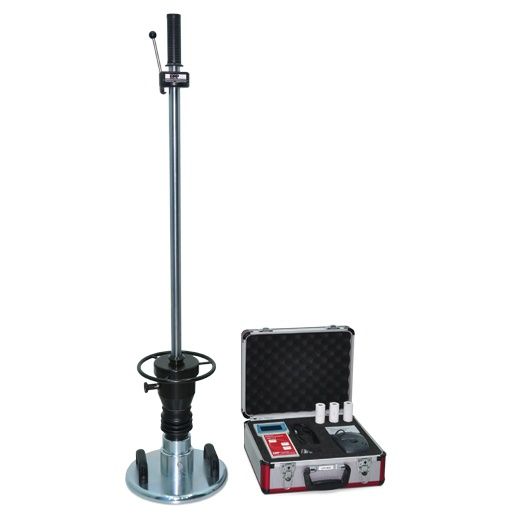
Product Code
|
UTS-1250 |
Light Weight Deflectometer |
Standards
ASTM E2835-11
The Light Weight Deflectometer makes it possible to quickly determine, in an uncomplicated manner, the soil bearing capacity and compaction quality of soils, non-cohesive sub-bases, and pavement improvements. The dynamic plate load tester is described in the Engineering Code for Soil and Rock in Road Construction.
In this way testing inbuilt soil layers can be carried out very quickly and without requiring a vehicle, which means it is also suitable for sites that are difficult to access. The machine is used in many areas - in road construction, railway engineering and earthworks for quality protection in canal construction and utility trenches, and in the examination of roadbeds and foundation fillings.
Due to the easy handling and the immediately available measurement results. The Light Weight Deflectometer is especially suitable for in house self-monitoring.
The deflectometer is a very reliable device with a ergonomic design and special structure. It can be transported and operated easily by only one person. The transportation lock on the drop weight ensures safety.
The load plate is equipped with practical handgrips, and the bubble level helps with the exact alignment of the loading mechanism. Despite this precision, the Light Weight Deflectometer (LWD) is very robust and long-lived: it is made using only the very best of materials. Naturally, the measurement device is splash proof and can be used in all weather conditions.
59. Constant Head Permeability Cells, ASTM
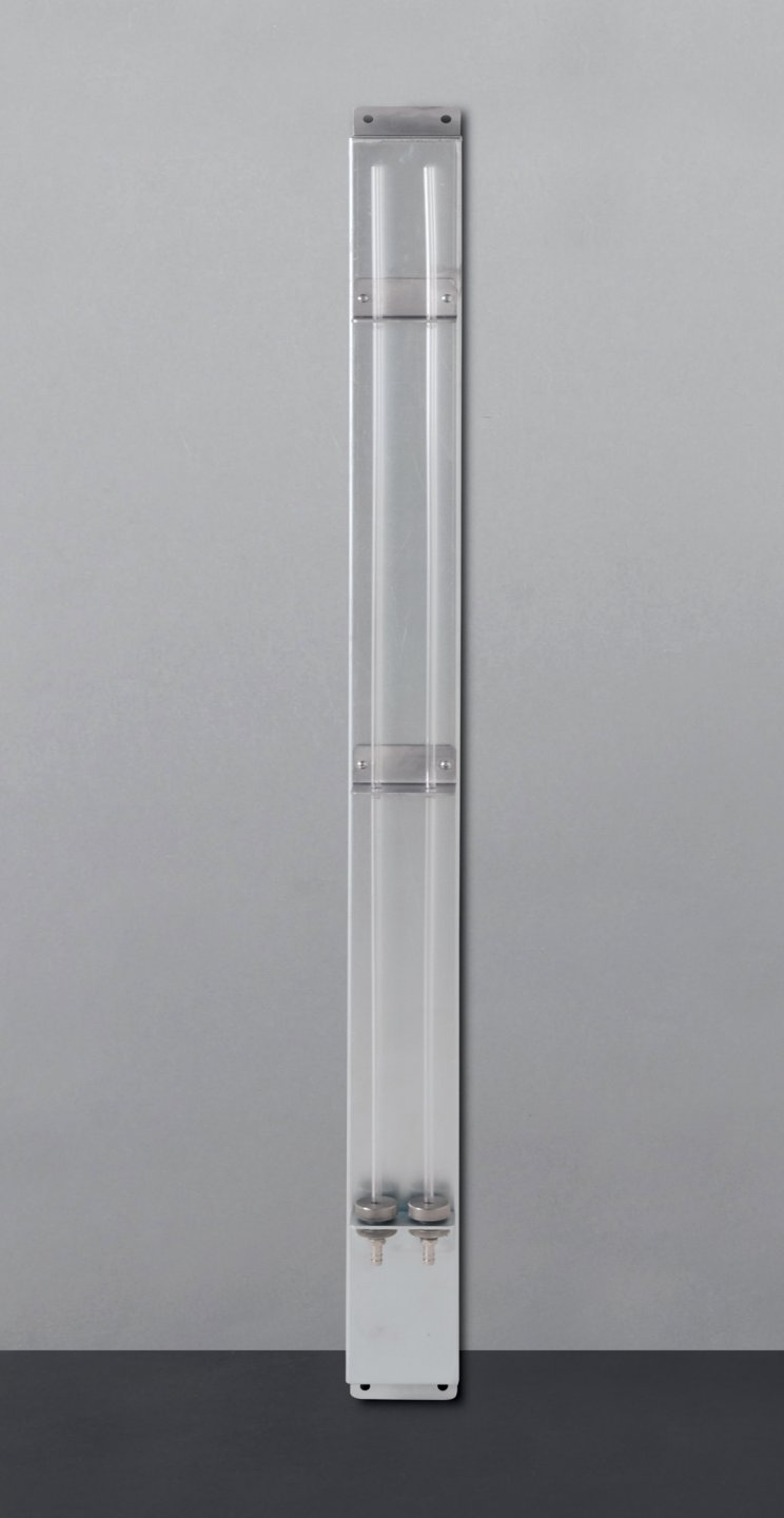
Product Code
|
UTS-1302A |
Constant Head Permeability Cell, ASTM 80 mm dia. (nominal) with transparent plexy body |
|
UTS-1303A |
Constant Head Permeability Cell, ASTM 120 mm dia. (nominal) with transparent plexy body |
|
UTS-1305A |
Wall Type Metal Manometer Panel with Two Tubes |
|
UTS-1306A |
Sliding Tamper, ASTM, |
|
UTS-1309A |
Constant-Head Filter Tank, 4 L. (Supplied without sand) |
|
UTS-1311A |
Constant Head Permeability Cell, ASTM 63 mm (2.5”) dia. with metal body |
|
UTS-1312A |
Constant Head Permeability Cell, |
|
UTS-1313A |
Constant Head Permeability Cell, |
|
UTS-1314A |
Constant Head Permeability Cell, |
|
UTS-1315A |
Constant Head Permeability Cell, |
|
UTGP-1140 |
Plastic Hose, Ø8 mm OD, 3 m |
Standards
ASTM D 2434
Constant Head Permeability Cells are used to study the behaviour of soil, relatively coarse-grained soil such as sands and gravel, in its natural conditions with respect to water flow.
The cells have an transparent plexy or metal body with 2 pressure points at different level and aluminium base and head.
UTS-1305A Wall type metal manometer panel is fitted with 2 manometer tubes each being 1000 mm long. Each tube has its own valve.
UTS-1309A Constant-Head Filter Tank, made of transparent plexy, has separate valves for inlet, outlet and overflow. Supplied with metal carriying case for wall mounting.
The Manometers Panel, Sliding Tamper, UTS-1309A Constant-Head Filter Tank and The Equipment for De-Airing Water should be ordered separately.
The Constant Head Permeability Cells are supplied complete with;
- Perforated plates and No.100 screen (each 2pcs.).
UTS-1305A
|
Product Code |
Dimensions |
Weight (approx.) |
|
UTS-1302A |
140x220x420 mm |
4 kg |
|
UTS-1303A |
180x250x640 mm |
7 kg |
|
UTS-1305A |
250x250x200 mm |
2 kg |
|
UTS-1306A |
50x50x400 mm |
2 kg |
|
UTS-1309A |
200x300x200 mm |
5 kg |
|
UTS-1311A |
200x200x350 mm |
5 kg |
|
UTS-1312A |
250x250x350 mm |
7 kg |
|
UTS-1313A |
300x300x350 mm |
8 kg |
|
UTS-1314A |
350x350x350 mm |
10 kg |
|
UTS-1315A |
400x400x350 mm |
10 kg |
60. Constant Head Permeability Set, BS
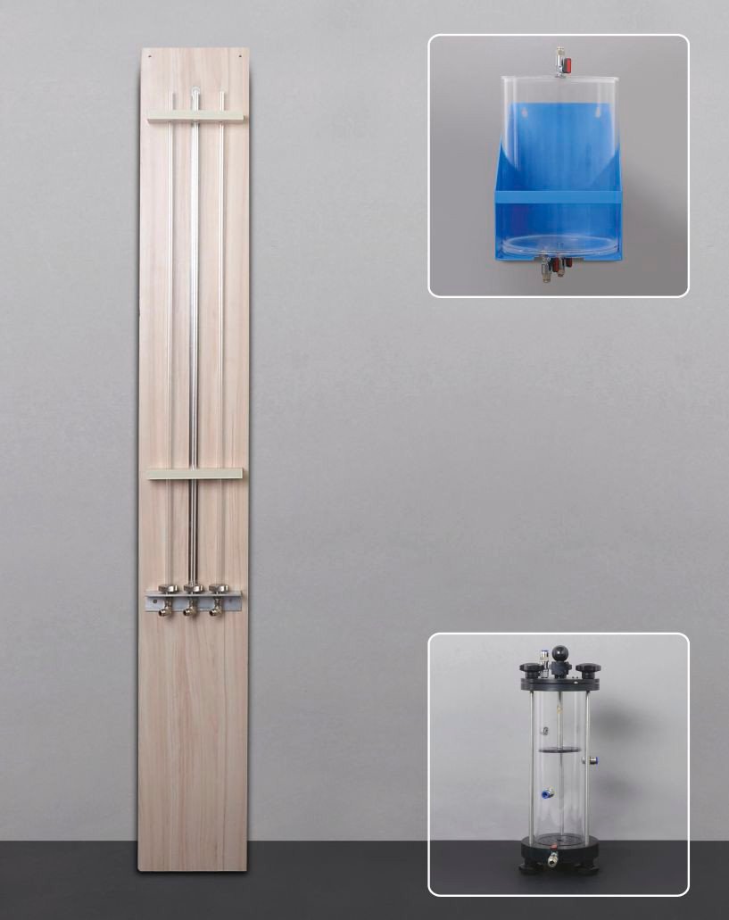
Product Code
|
UTS-1300B |
Constant Head Permeability Set, BS, |
|
UTS-1302B |
Constant Head Permeability Cell, BS, |
|
UTS-1305B |
Wooden Stand with 3 Manometer Tubes |
|
UTS-1308 |
Constant Level Water Tank, 7 L. |
|
UTA-0645 |
Tamping Rod Ø 8x300 mm |
Standards
BS 1377:5
The UTS-1300B Constant Head Permeability Set is used to study the behaviour of soil, relatively coarse-grained soil such as sands and gravel, in its natural conditions with respect to water flow.
UTS-1302B cell has 3 pressure points.
UTS-1305B Wooden stand is fitted with 3 glass manometer tubes each being 1000 mm long.
UTS-1308 Constant Level Tank 7 L, made of transparent plastic, is used to provide constant water level in the manometer tubes.
Optional Equipment For De-Airing Water and Tamping Rod should be ordered separately.
The Constant Head Permeability Sets are supplied complete with;
- Ø 80 mm Permeability Cell with Pressure Points at 3 different levels and 2 pcs. Wire Gauze fit for the prefered cell dia.
- Constant Level Water Tank (UTS-1308)
- Wooden Stand with 3 manometer tubes
- 10 m Hose (UTGP-1145)
|
Product Code |
Dimensions |
Weight (approx.) |
|
UTS-1302B |
140x220x420 mm |
3.5 kg |
|
UTS-1305B |
220x70x1700 mm |
5.6 kg |
|
UTS-1308 |
300x200x250 mm |
3 kg |
|
UTA-0645 |
Ø 8x300 mm |
0.5 kg |
UTS-1302B UTS-1308 UTS-1330 UTGG-2016/UTGP-1140 UTGE-3505
Constant Head Permeability Test with De-Airing Water System
61. Falling Head Permeability Set
Product Code
|
UTS-1320 |
Falling Head Permeability Set |
|
UTS-1322 |
Falling Head Permeability Cell 100 mm dia. |
|
UTS-1324 |
Wooden Stand with 3 Manometer Tubes |
|
UTS-1326 |
Soaking Reservoir Tank |
Standards
EN ISO 17892-11
The UTS-1320 Falling Head Permeability Set is used to study the behaviour of soil, particularly finegrained soils such as clay-like or silty soils, with respect to water flow.
The UTS-1322 Falling Head Permeability Cell is manufactured from plated steel with an inside diameter of 100 mm.
The UTS-1324 Wooden Stand is fitted with 3 glass Manometer Tubes of each 1500 mm long with inside diameters of about 12 mm, 5 mm and 3.5 mm. All tubes have connection valves.
The UTS-1326 Soaking Reservoir Tank is manufactured from plated steel with an over-flow tube and is used for containing the permeability cell during the test.
Optional Equipment For De-Airing Water should be ordered separately.
The UTS-1320 Falling Head Permeability Set is supplied complete with;
- Ø 100 mm Falling Head Permeability Cell
- Wooden Stand with 3 manometer tubes
- Soaking Reservoir Tank
- 3 m Hose (UTGP-1440)
|
Product Code |
Dimensions |
Weight (approx.) |
|
UTS-1322 |
150x150x260 mm |
3 kg |
|
UTS-1324 |
220x135x1700 mm |
4,5 kg |
|
UTS-1326 |
320x320x250 mm |
3.6 kg |
UTS-3505 UTGG-2016/UTGP1140 UTS-1330 UTS-1326 UTS-1322 UTGE-3580
Falling Head Permeability Test with De-Airing Water System
62. Compacted Soil Permeability Cells
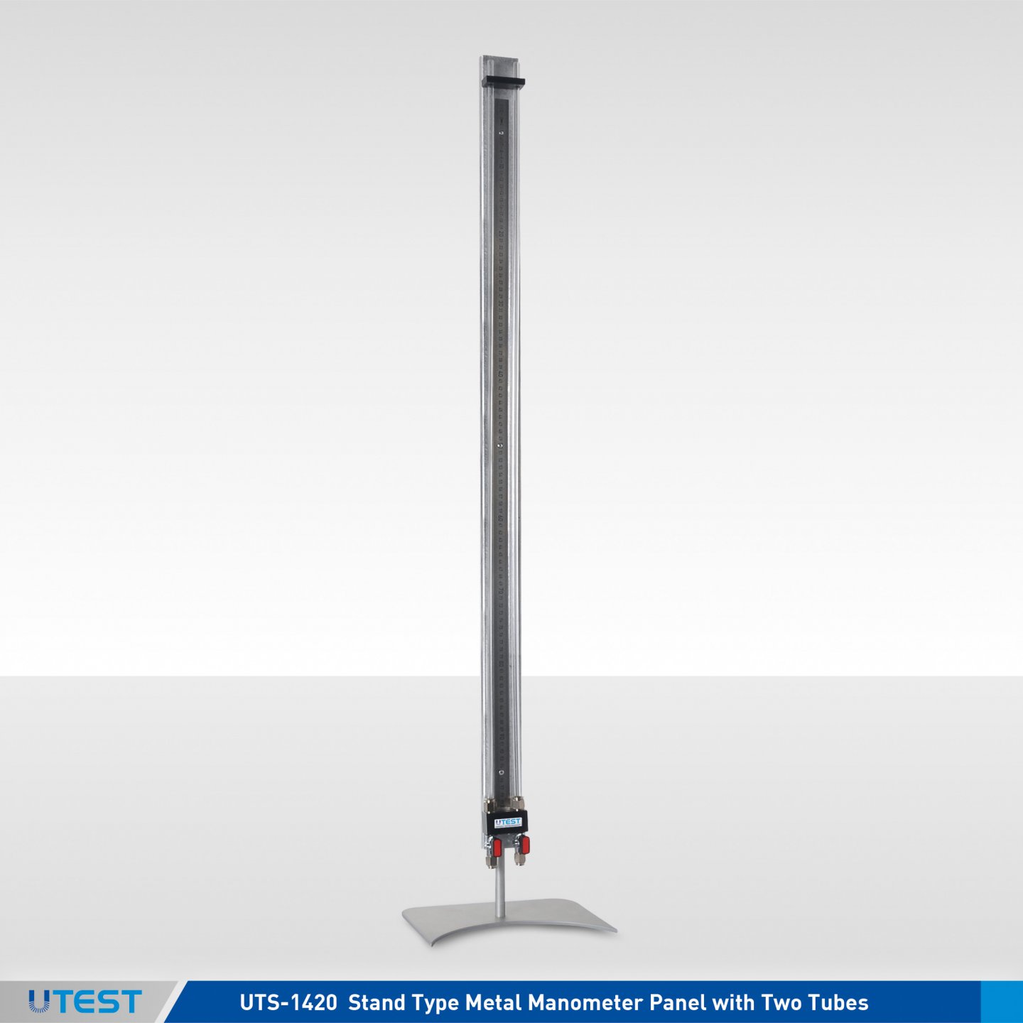
Product Code
|
UTS-1403 |
Compaction Permeameter Mould without Swell Ring. Ø 4” |
|
UTS-1404 |
Compaction Permeameter Mould without Swell Ring. Ø 6” |
|
UTS-1407 |
Compaction Permeameter Mould without Swell Ring, Ø105 mm |
|
UTS-1420 |
Stand Type Metal Manometer Panel with Two Tubes |
|
UTGP-1140 |
Plastic Hose, Ø8 mm OD, 3 m |
Standards
ASTM D5856
The Compaction Permeameter Moulds are used together with UTS-1420 Stand type metal manometer panel for determining the water permeability of compacted soil specimens like clay, sand, gravel etc.
Stand Type Metal Manometer Panel is 1000 mm in lenght and graduated in mm.Each tube has its own valve.
Stand type metal manometer panel (UTS-1420) and plastic hose should be ordered seperately
UTS-1404 and UTS-1407 are supplied with perforated plates and No.100 screen (each 2pcs.). UTS-1403 is supplied with two prous discs.
|
Product Code |
Dimensions |
Weight (approx.) |
|
UTS-1420 |
200x100x1100 mm |
6 kg |
|
UTS-1403 |
150x150x220 mm |
7,5 kg |
|
UTS-1404 |
200x200x700 mm |
15 kg |
63. Pinhole Test Apparatus
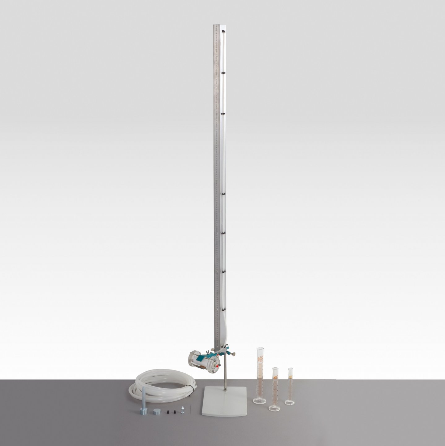
Product Code
|
UTS-1500 |
Pinhole Test Apparatus, Ø33mm ID |
|
UTS-1504 |
Pinhole Test Apparatus, Ø44mm ID |
|
UTS-1308 |
Constant Level Water Tank, 7 L. |
Standards
BS 1377:5; ASTM D4647; TS 1900-2
Water flowing through fine-grained soils with high sodium content makes them highly erodible.
The UTS-1500 and UTS-1504 Pinhole Test Apparatus are used for evaluating the erodibility of clay soils by flowing water through a small hole that is drilled through the compacted specimen.
The apparatus consist of a cylindrical plexiglass body (container) fitted top cap with a water inlet and the base cap with an outlet connection, a plastic nipple, a plastic centering guide, a wire punch (1.0 mm), a stand to support the apparatus with 1100mm scale and standpipe tube(Ø4mm IDx6mm OD), four pcs wire mesh, 1,5m pvc tubing with a valve, 10ml, 25ml and 50 ml graduated glass measuring cylinders and an anvil with a tamper (fit with the body of ordered apparatus).
Constant level water tank (UTS-1308) and de-airing water equipment should be ordered separately.
If required, different inner diameter plexiglass bodys with caps can be produced.
|
Product Code |
UTS-1500 |
UTS-1504 |
|
Dimensions |
150x200x1200 mm |
50x100x50 mm |
|
Weight (approx.) |
4 kg |
1 kg |
64. Fully-Automated Triaxial and Strees Path System
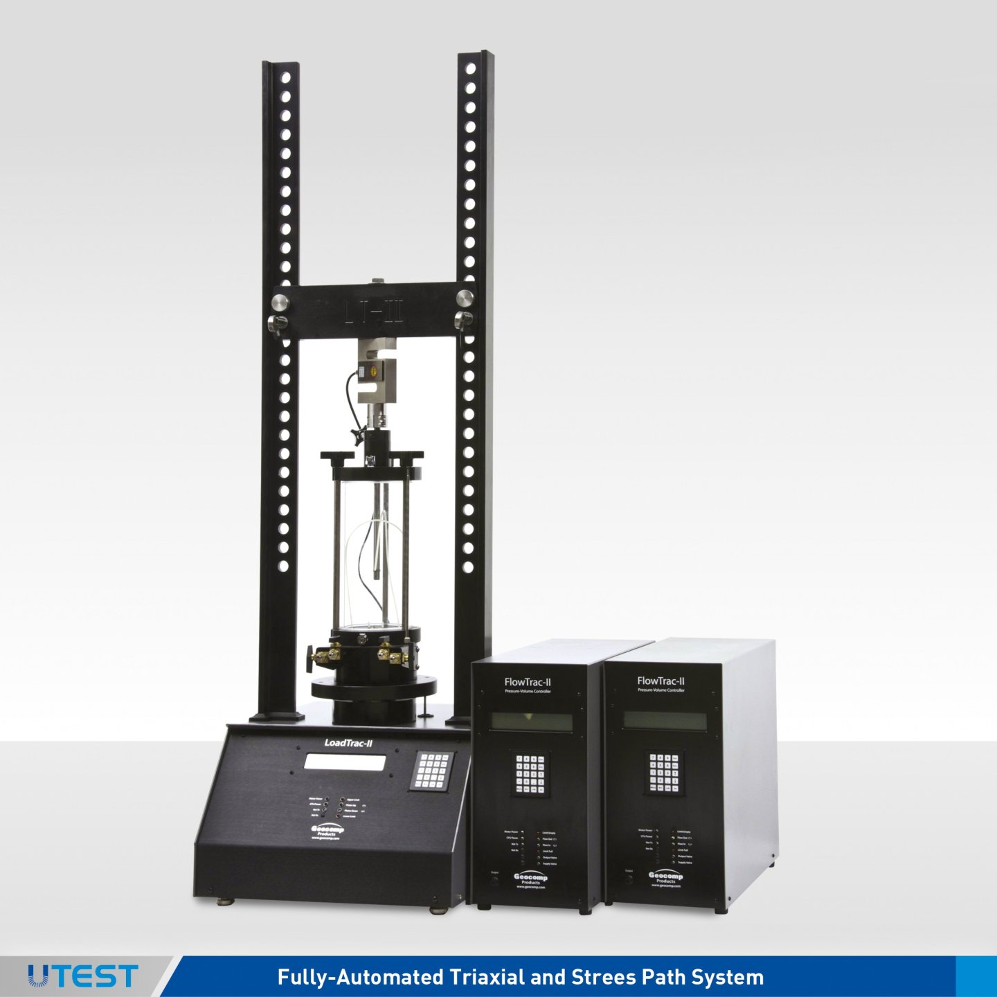
Product Code
LoadTrac II
FlowTrac II
The Load Trac-II/FlowTrac-II system fully auto mates the performance of a Controlled Strain Loading Consolidation (CSL) test. Once a soil sample is in place, and the test conditions selected, the LoadTrac-II/ FlowTrac-II system will run the entire CRCS test from start to finish. The LoadTrac II/ FlowTrac-II system consolidates the sample through a loading path specified by the user using constant rate of strain loading. To avoid running the test too fast (excess pore pressures become too large for the transducer) or too slow (the test takes too long), LoadTrac II/FlowTrac-II uses Excess Pore Pressure Ratio Limits. If the measured excess pore pressure divided by the current total vertical stress exceeds the Upper Pore Pressure Ratio Limit, the current strain rate is automatically decreased by a factor of 2. If the measured excess pore pressure divided by the current total vertical stress falls below the Lower Pore Pressure Ratio Limit, the current strain rate is increased by a factor of 2. These limits give the user a great deal of control over how a constant strain rate test is run.
The FlowTrac II is used during back pressure saturation as well as maintaining a constant cell pressure during the consolidation phase of the test. A typical consolidation test can be completed in 24 to 36 hrs. on most materials.
Applicable Test Standards
- ASTM D-4186 One-Dimensional Consolidation
- Properties of Soils Using Controlled - Strain Loading
User Benefits
- Choose capacity to fit user needs from 22, 45 and 90 kN (5,000, 10,000 and 20,000 lbs.) models
- Total automation of data collection and reporting of test results
- Prepare tables and plots of report quality within minutes of completing a test
- Generate columns of data for easy reduction using your own spreadsheet software
- Ability to access and control the unit over a computer network using Geo-Net option
Technical Specifications
|
Motor |
Stepper motor with built-in controls |
|
Travel |
Built-in displacement transducer with 76 mm (3 in.) range and 0.0013 mm(0.00005 in) resolution |
|
Displacement |
Control from 0.00003 to 15 mm per minute (0.000001 to 0.6 in. per minute) |
|
Flow Range |
0.000006 to 3 cc per second |
|
Power |
110/220 V, 50/60 Hz, 1phase |
Models
|
FlowTrac II Models |
|
|
FTII-250-nn |
250 cc capacity |
|
FTII-750-nn |
750 cc capacity |
|
LoadTrac II Models |
|
|
LTII-5,000 |
22 kN (5,000 lbs.) frame capacity |
|
LTII-10,000 |
45 kN (10,000 lbs.) frame capacity |
|
LTII-20,000 |
90 kN (20,000 lbs.) frame capacity |
|
LTII-50,000 |
222 kN (50,000 lbs.) frame capacity |
Accessories
|
1230 |
All stainless steel consolidation cell with backpressure saturation capability, 62.5mm (2.5 in.) sample diameter standard. External stainless steel pressure sensor. Other sample sizes are available upon request |
|
Product Code |
Dimensions |
Weight (approx.) |
|
LoadTrac II |
464 x 546 x1206 mm (18 x 21.5 x 47.5 in.) |
55 kg |
|
FlowTrac II |
203 x 406 x 470 mm (8 x 16 x 18.5 in.) |
14 kg |
65. Fully-Autometed Unconfined Compression System
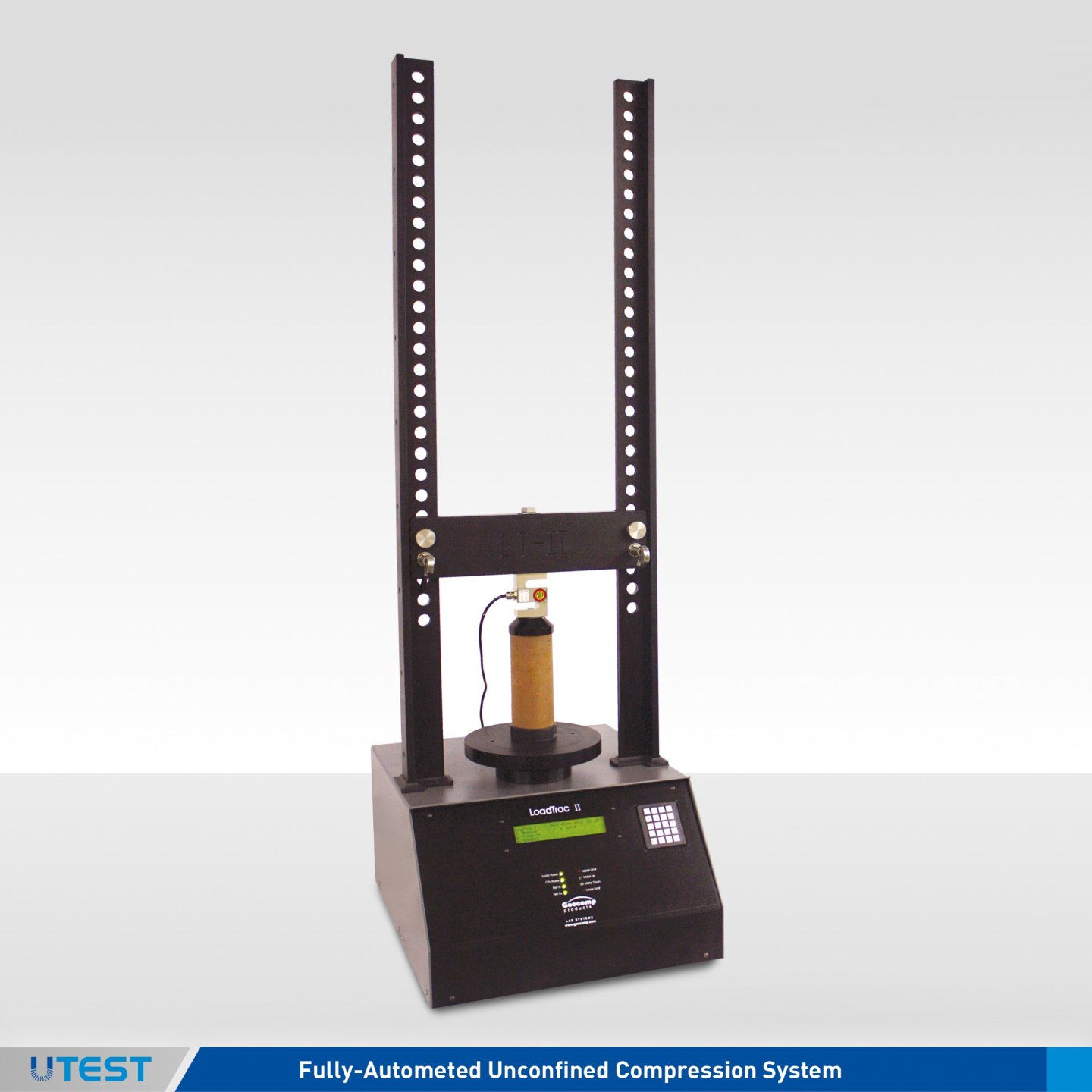
Product Code
LoadTrac II
The LoadTrac II load frame provides compression/extension testing for a number of geotechnical tests that must have accurate control of the rate of dis-placement during loading. With acces-sories, the unit can perform uncon-fined compression, CBR, and triaxial shear phase testing.
The base unit includes a stepper mo-tor, lead screw, vertical tension rods and crosshead, displacement trans-ducer, electronic controls and network communications. Versions of the unit are available to test loads up to 90 kN (20,000 lbs.). Displacement rates can be set to any value between 0.00003 and 15 mm per minutes (0.000001 to 0.6 inches per minute).
The base unit can run in stand-alone mode without a computer. It includes built-in data acquisition and display capability. Sensor readings are dis-played in Sl or English units and stored in memory.
Optional software running in Win-dows® 2000, XP, Vista, 7 completely automates the test, reducing the data and preparing test results.
Applicable Test Standards
- ASTM D-2166, AASHTO T-208 Unconfined Compression Testing of Soils
- ASTM D-1663 Compressive Strength of Molded Soil-Cement Cylinders
User Benefits
- Choose capacity to fit user needs from 22, 45 and 90 kN (5,000, 10,000 and 20,000 lbs.) models
- Total automation of data collection and reporting of test results
- Prepare tables and plots of report quality within minutes of completing a test
- Generate columns of data for easy reduction using your own spreadsheet software
- Ability to access and control the unit over a computer network using Geo-Net option
Technical Specifications
|
Motor |
Stepper motor with built-in controls |
|
Travel |
Built-in displacement transducer with 76 mm (3 in.) range and 0.0013 mm(0.00005 in) resolution |
|
Displacement |
Control from 0.00003 to 15 mm per minute (0.000001 to 0.6 in. per minute) |
|
Power |
110/220 V, 50/60 Hz, 1phase |
|
Dimensions |
464x546 x1206 mm |
|
Weight (approx.) |
55 kg |
Models
|
LTII-5,000 |
22 kN (5,000 lbs.) frame capacity |
|
LTII-10,000 |
45 kN (10,000 lbs.) frame capacity |
|
LTII-20,000 |
90 kN (20,000 lbs.) frame capacity |
|
LTII-50,000 |
222 kN (50,000 lbs.) frame capacity |
Accessories
|
7020 |
75 mm (3.0 in) platen with load cell adaptor |
|
Geo NET™ |
Network/Communication card and cable to link load frame to PC. |
|
UC |
Software package to automatically run and report UC tests |
Option
|
UC Report |
Editing/reporting software for multiple tests |
66. Fully-Automated California Bearing Ratio System
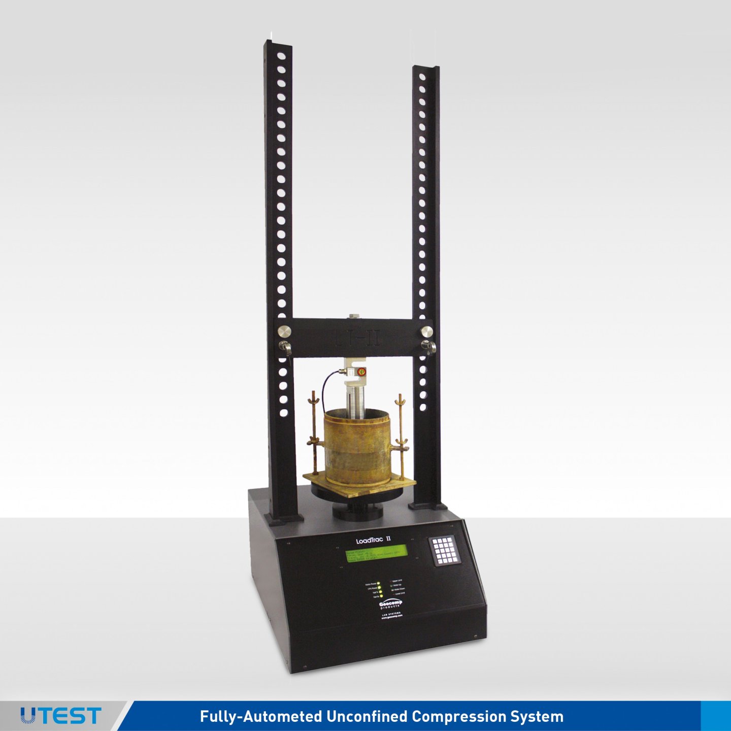
Product Code
LoadTrac II
The LoadTrac II load frame provides compression/extension testing for a number of geotechnical tests that must have accurate control of the rate of dis-placement during loading. With acces-sories, the unit can perform uncon-fined compression, CBR, and triaxial shear phase testing.
The base unit includes a stepper mo-tor, lead screw, vertical tension rods and crosshead, displacement trans-ducer, electronic controls and network communications. Versions of the unit are available to test loads up to 90 kN (20,000 lbs.). Displacement rates can be set to any value between 0.00003 and 15 mm per minutes (0.000001 to 0.6 inches per minute).
The base unit can run in stand-alone mode without a computer. It includes built-in data acquisition and display capability. Sensor readings are dis-played in Sl or English units and stored in memory.
Optional software running in Win-dows® 2000, XP, Vista, 7 completely automates the test, reducing the data and preparing test results.
Applicable Test Standards
- ASTM D-2166, AASHTO T-208 Unconfined Compression Testing of Soils
- ASTM D-1663 Compressive Strength of Molded Soil-Cement Cylinders
User Benefits
- Choose capacity to fit user needs from 22, 45 and 90 kN (5,000, 10,000 and 20,000 lbs.) models
- Total automation of data collection and reporting of test results
- Prepare tables and plots of report quality within minutes of completing a test
- Generate columns of data for easy reduction using your own spreadsheet software
- Ability to access and control the unit over a computer network using Geo-Net option
Technical Specifications
|
Motor |
Stepper motor with built-in controls |
|
Travel |
Built-in displacement transducer with 76 mm (3 in.) range and 0.0013 mm(0.00005 in) resolution |
|
Displacement |
Control from 0.00003 to 15 mm per minute (0.000001 to 0.6 in. per minute) |
|
Power |
110/220 V, 50/60 Hz, 1phase |
|
Dimensions |
464x546 x1206 mm |
|
Weight (approx.) |
55 kg |
Models
|
LTII-5,000 |
22 kN (5,000 lbs.) frame capacity |
|
LTII-10,000 |
45 kN (10,000 lbs.) frame capacity |
|
LTII-20,000 |
90 kN (20,000 lbs.) frame capacity |
|
LTII-50,000 |
222 kN (50,000 lbs.) frame capacity |
Accessories
|
7020 |
CBR plunger with load cell adapter. |
|
Geo NET™ |
Network/Communication card and cable to link load frame to PC. |
|
UC |
Software package to automatically run and report CBR tests |
Option
|
UC Report |
UC, consolidation, and triaxial testing modules |
67. Fully-Automated Constant Rate of Strain Consolidation System
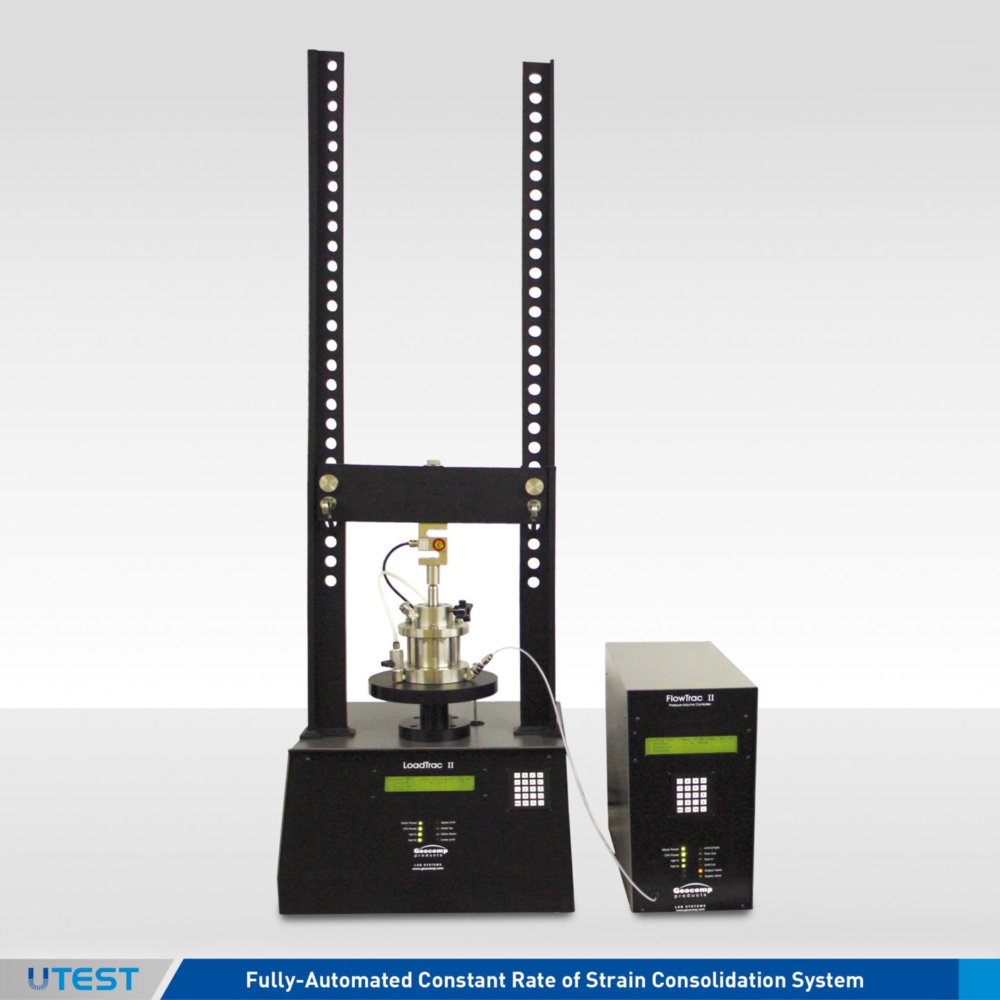
Product Code
LoadTrac II
FlowTrac II
The Load Trac-II/FlowTrac-II system fully auto mates the performance of a Controlled Strain Loading Consolidation (CSL) test. Once a soil sample is in place, and the test conditions selected, the LoadTrac-II/ FlowTrac-II system will run the entire CRCS test from start to finish. The LoadTrac II/ FlowTrac-II system consolidates the sample through a loading path specified by the user using constant rate of strain loading. To avoid running the test too fast (excess pore pressures become too large for the transducer) or too slow (the test takes too long), LoadTrac II/FlowTrac-II uses Excess Pore Pressure Ratio Limits. If the measured excess pore pressure divided by the current total vertical stress exceeds the Upper Pore Pressure Ratio Limit, the current strain rate is automatically decreased by a factor of 2. If the measured excess pore pressure divided by the current total vertical stress falls below the Lower Pore Pressure Ratio Limit, the current strain rate is increased by a factor of 2. These limits give the user a great deal of control over how a constant strain rate test is run.
The FlowTrac II is used during back pressure saturation as well as maintaining a constant cell pressure during the consolidation phase of the test. A typical consolidation test can be completed in 24 to 36 hrs. on most materials.
Applicable Test Standards
- ASTM D-4186 One-Dimensional Consolidation
- Properties of Soils Using Controlled - Strain Loading
User Benefits
- Choose capacity to fit user needs from 22, 45 and 90 kN (5,000, 10,000 and 20,000 lbs.) models
- Total automation of data collection and reporting of test results
- Prepare tables and plots of report quality within minutes of completing a test
- Generate columns of data for easy reduction using your own spreadsheet software
- Ability to access and control the unit over a computer network using Geo-Net option
Technical Specifications
|
Motor |
Stepper motor with built-in controls |
|
Travel |
Built-in displacement transducer with 76 mm (3 in.) range and 0.0013 mm(0.00005 in) resolution |
|
Displacement |
Control from 0.00003 to 15 mm per minute (0.000001 to 0.6 in. per minute) |
|
Flow Range |
0.000006 to 3 cc per second |
|
Power |
110/220 V, 50/60 Hz, 1phase |
Models
|
FlowTrac II Models |
|
|
FTII-250-nn |
250 cc capacity |
|
FTII-750-nn |
750 cc capacity |
|
LoadTrac II Models |
|
|
LTII-5,000 |
22 kN (5,000 lbs.) frame capacity |
|
LTII-10,000 |
45 kN (10,000 lbs.) frame capacity |
|
LTII-20,000 |
90 kN (20,000 lbs.) frame capacity |
|
LTII-50,000 |
222 kN (50,000 lbs.) frame capacity |
Accessories
|
1230 |
All stainless steel consolidation cell with backpressure saturation capability, 62.5mm (2.5 in.) sample diameter standard. External stainless steel pressure sensor. Other sample sizes are available upon request |
|
|
Dimensions |
Weight (approx.) |
|
LoadTrac II |
464 x 546 x1206 mm ( 18 x 21.5 x 47.5 in. ) |
55 kg |
|
FlowTrac II |
203 x 406 x 470 mm (8 x 16 x 18.5 in.) |
14 kg |
68. Fully Automated Consolidation & Swell System
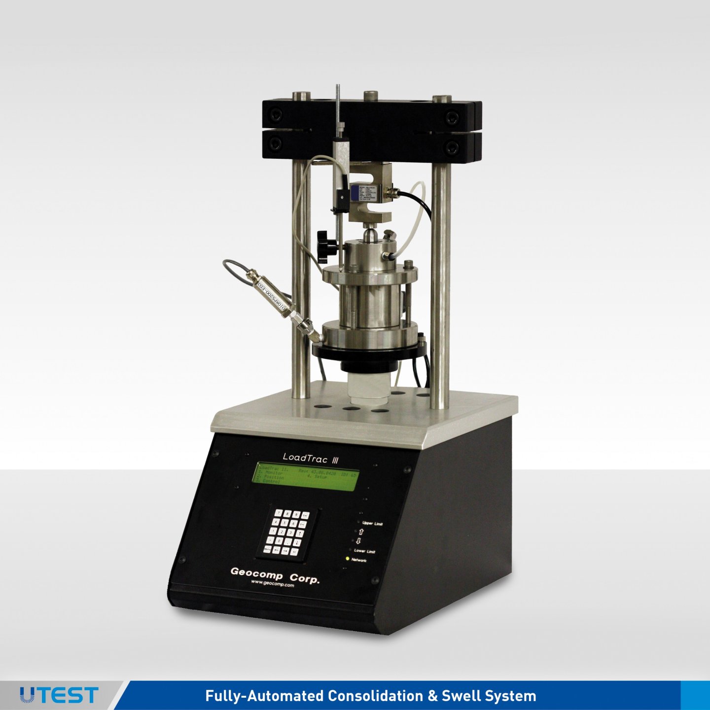
Product Code
LoadTrac III (Mini-LoadTrac)
LoadTrac III system for incremental consolidation and swell testing fully automates an entire consolidation test. Constant load and constant volume swell tests can be run automatically. Once a sample is placed into the load frame, the test conditions programmed, and the test started, the LoadTrac III system performs the complete test up to 32 steps without intervention by the user. The computer automatically increments to the next stress by using conditions specified by the user. Incremental consolidation test can be completed in 24 to 48 hours on most materials.
The LoadTrac III system utilizes a high speed, precision microstepper motor to apply the vertical load to the soil specimen. An embedded control board with a dedicated CPU takes readings from the force transducer and displacement transducer to control the stepper motor.
The base unit includes built-in data acquisition and display capability. Sensor readings are displayed in SI or English units and stored in memory. For incremental consolidation, the base unit is linked to a PC using the network communications module and the appropriate software.
Optional software running in Windows® 2000, XP, Vista, 7 completely automates the test, reducing the data and preparing test results.
Other options include running constant rate of consolidation, unconfined compression and triaxial on a 50 mm (2.00 in.) or less diameter sample.
Applicable Test Standards
- ASTM D-2435 Incremental Consolidation
- AASHTO T-216 Incremental Consolidation
- ASTM D-4546 One dimensional swell or settlement potential of cohesive soils
User Benefits
- Total automation, control, data collection and reporting of test results
- Prepare tables and plots of report quality within minutes of completing a test
- Generate columns of data for easy reduction using your own spreadsheet software
- Ability to access and control the unit over a computer network using Geo-Net option
Technical Specifications
|
Capacity |
11 kN (2,500 lbs.) |
|
Motor |
Stepper motor with built-in controls |
|
Travel |
25 mm (1.0 inches) resolved to 0.0025 mm (0.0001 inches) |
|
Clearance |
180 mm (7 inches) horizontal between uprights, 150 mm (6 inches) vertical platen to crosshead standard |
|
Power |
110/220 V, 50/60 Hz, 1 phase |
Accessories
|
1220 |
All stainless steel consolidation cell includes 63.5 mm (2.5 in.) sample ring, top cap, top and bottom porous stones. |
|
1230 |
Consolidation cell with back pressure saturation capability, 62.5 mm (2.5 in.) sample diameter standard. Other sizes available upon request with optional external stainless steel pressure sensor. |
|
Geo NET™ |
Network/Communication card and cable to link load frame to PC. |
|
ICONP |
Software package to automatically run incremental consolidation test and swell tests with built-in editing reporting option. |
|
Dimensions |
305 x 381 x 838 mm |
|
Weight (approx.) |
20 kg |
69. Fully-Automated Permeability System
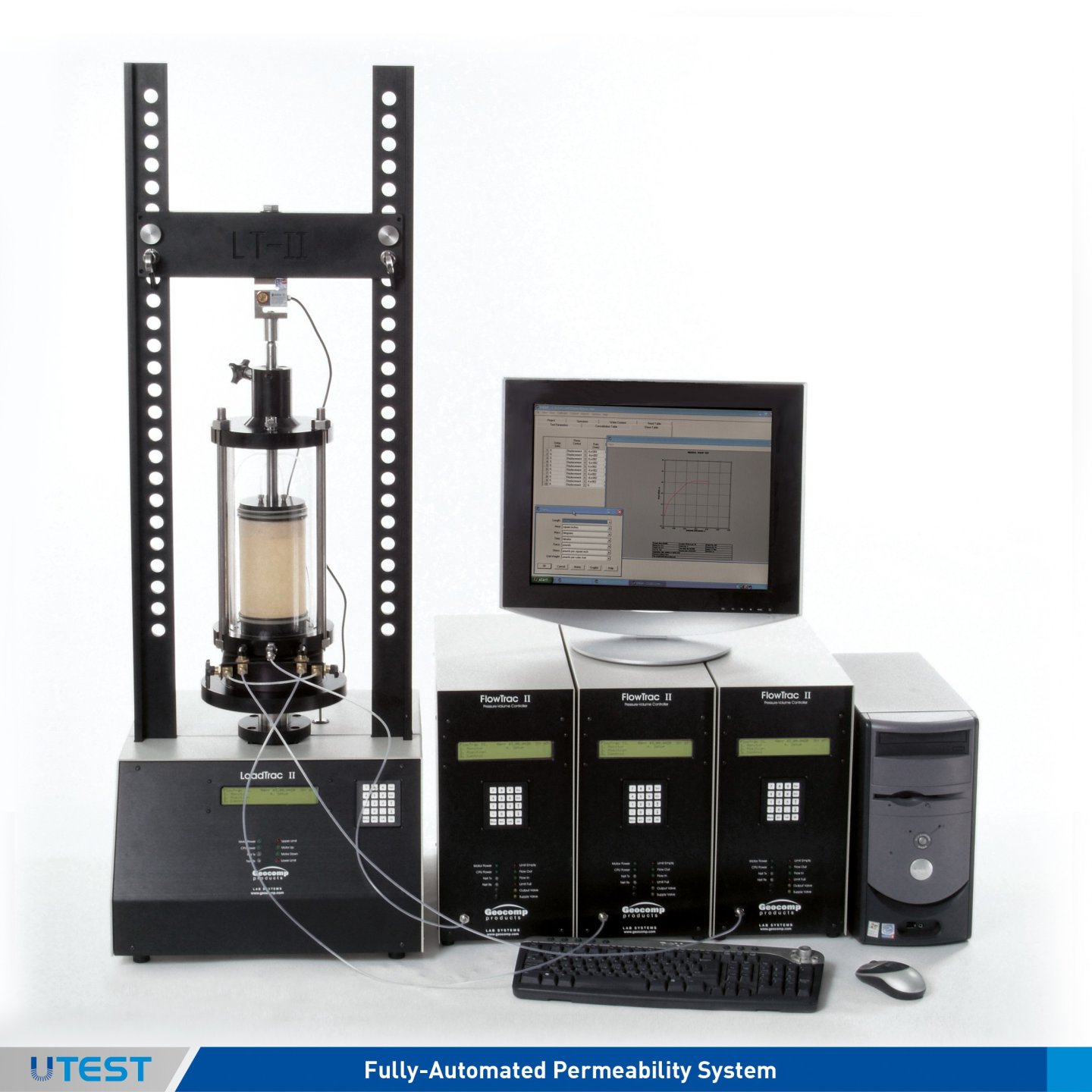
Product Code
LoadTrac II
FlowTrac II
The LoadTrac II/FlowTrac II flow pump provides a unique and versatile way to run flexible wall permeability tests on a wide variety of materials quickly and accurately. By adjusting the gradient or the flow rate across the sample, the system can measure permeabilities of cohesive soils varying from 10-4 cm/sec to 10-9 cm/sec. With the appropriate test cells, this one system can determine the permeability of some silty clays within minutes.
The FlowTrac-II base unit includes a stepper motor, lead screw, pressure chamber and piston, pressure transducer, electronic controls and network communications. Versions of the unit are available with flow volumes of 250 cc and 750 cc. Flow rates can be set to any value between 0.000006 cc/sec. and 3.0 cc/sec. Flexible wall tests are run in a fully automated mode with three flow pumps and one LoadTrac-II; the FlowTrac-II's controls cell pressure and flow of cell, bottom sample and top sample. This configuration allows great versatility to run fully automated permeability tests with isotropic, anisotropic or Ko consolidation.
With the network communications module and the appropriate software, the entire test can be automatically controlled, data captured and displayed in real time, and test reports prepared on a PC. With GeoNet-LAN option, the test can be monitored and data reported from any PC located on a LAN to which the LoadTrac II/FlowTrac II system is connected.
® Control and editing software runs in Windows 2000, XP, Vista 7
Applicable Test Standards
- ASTM D-5084 - Flexible wall permeability
- ASTM D-2434 - Rigid wall permeability
User Benefits
- Choose load capacity to fit user needs from 10, 22, 45, and 90kN (2,000, 5,000,10,000, and 20,000 lbs.) models
- Total automation, control, data collection and reporting of test results
- Prepare tables and plots of report quality within minutes of completing a test
- Geo-NET compatibility lets unit be accessed and controlled over a computer network
- Generate columns of data for easy reduction using your own spreadsheet software
- Choose volume capacity to fit user needs from 250, and 750 cc models
- Accurate displacement rate control from 0.00003 to15 mm per minute (0.000001 to 0.6 in. per minute)
- Accurate pressure and volume measurements with integrated sensors
- Stand alone through front keypad and LCD menu,
Accessories
- Triaxial/Permeability cells up to 150mm (6.00 in.) diameter, membranes, porous stones and sample preparation accessories upon request.
- Geo-NET PC network card and cable to link LoadTrac II / FlowTrac II to PC
Technical Specifications
|
Motor |
Stepper motor with built-in controls |
|
Travel |
Built-in displacement transducer with 76 mm (3 in.) range and 0.0013 mm(0.00005 in) resolution |
|
Displacement |
Control from 0.00003 to 15 mm per minute (0.000001 to 0.6 in. per minute) |
|
Flow Range |
0.000006 to 3 cc per second |
|
Power |
110/220 V, 50/60 Hz, 1 phase |
|
|
Dimensions |
Weight (approx.) |
|
LoadTrac II |
464 x 546 x1206 mm ( 18 x 21.5 x 47.5 in. ) |
55 kg |
|
FlowTrac II |
203 x 406 x 470 mm (8 x 16 x 18.5 in.) |
14 kg |
Models
|
FlowTrac II Models |
|
|
FTII-250-nn |
250 cc capacity |
|
FTII-750-nn |
250 cc capacity |
|
LoadTrac II Models |
|
|
LTII-5,000 |
22 kN (5,000 lbs.) frame capacity |
|
LTII-10,000 |
45 kN (10,000 lbs.) frame capacity |
|
LTII-20,000 |
90 kN (20,000 lbs.) frame capacity |
|
LTII-50,000 |
222 kN (50,000 lbs.) frame capacity |
70. Fully-Automated Cyclic Trixial System
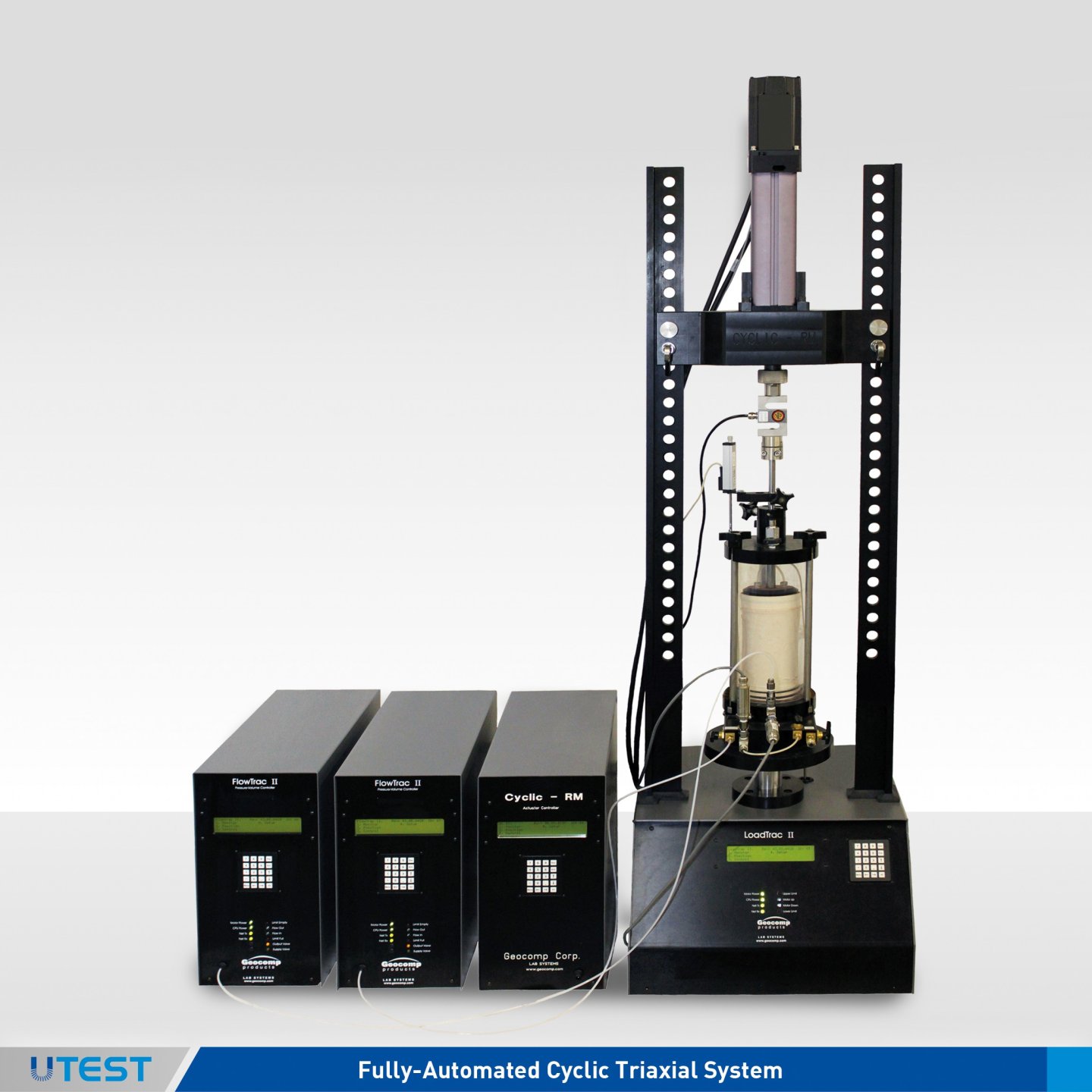
Product Code
LoadTrac II
FlowTrac II Cyclic
The LoadTrac II/FlowTrac II Cyclic system automated test unit completely automates cyclic triaxial testing of soils. Minimum mantime is required.
The LoadTrac II/FlowTrac-II Cyclic consists of a triaxial cell to retain the sample, a load frame with computercontrolled platen for static loading, two computer controlled flow pumps to control chamber pressure and back pressure, a high performance linear actuator servo control actuator for cyclic loading with update rates of 500 times per second, a micro-processor for accurately controlling cyclic loading, a PC with a Pentium processor to control the test, and to log test data. Editing and reporting is built-in to the test and control software program. The unit arrives in a completely selfcontained system with all necessary equipment.
The LoadTrac II/FlowTrac II Cyclic system is menu driven. The Windows® XP, Vista, 7 based software allows users to define the conditions for running the test, logging test data and reporting results. Users can specify the values for controlling the saturation, consolidation and cyclic loading of a test. During testing, current data and system status information is displayed. Collected data are written to a file on the system's hard drive. The reporting software performs all required calculations and permits users a variety of options in graphing and generating test data.
Applicable Test Standards
- ASTM D-3999 Determination of the Modulus Properties
- ASTM D-5311 Load Controlled Cyclic Triaxial Testing of Soils
Benefits and Features
- Reduces time required for testing
- Run tests on isotropically, anisotropically and Ko consolidated samples
- Select number of data points logged per cycle from 10 to 500 readings per second
- Reduce test error and improve quality control
- Operates in a Windows® XP/2000/Vista/7 environment
Technical Specifications
|
Cyclic Loading System |
High performance custom linear actuator 1.8kW peak, low inertia servo-drive system for fast response time. High resolution feedback system for precise and accurate control of load and speed. 4.4 kN (1000lbs force) continuous load at speeds in excess of 200 mm (8") /sec Self-contained and maintenance free Single Phase 208 VAC/60Hz (US) / 220VAC/50Hz (international) |
|
Type Of Cyclic Loading |
Load controlled sinusoidal shape |
|
Cyclic Rate |
Up to 10 Hz |
|
Options To End Test |
Maximum number of cycles Maximum strain |
|
Reporting Options |
Load, displacement, sample, and cell vs. cycle number, Shear stress, strain, p-p strain, excess pore pressure vs. cycle number, Shear stress vs. axial strain, Shear stress vs. normal stress, Automatic or user specified scaling on any of above plots, Plotting to monitor, printer, plotter, or file |
|
Test Cell |
Modified triaxial cell with accessories |
|
Unit Systems |
U.S., English, metric and SI changeable at any time before, during and after test |
|
Sample Diameter |
50, 70, up to 100 mm (2/2.8/4 inches) Custom sizes by special order |
|
Transducers |
Force: 2, 5,10 kN (500, 1000, 2500 lbf.) Displacement: 50mm (2.0 in.) range Cell and sample pressures: 0-1400 kPa (0-200 psi) |
71. Fully-Automated Resonant Column & Torsional Shear System
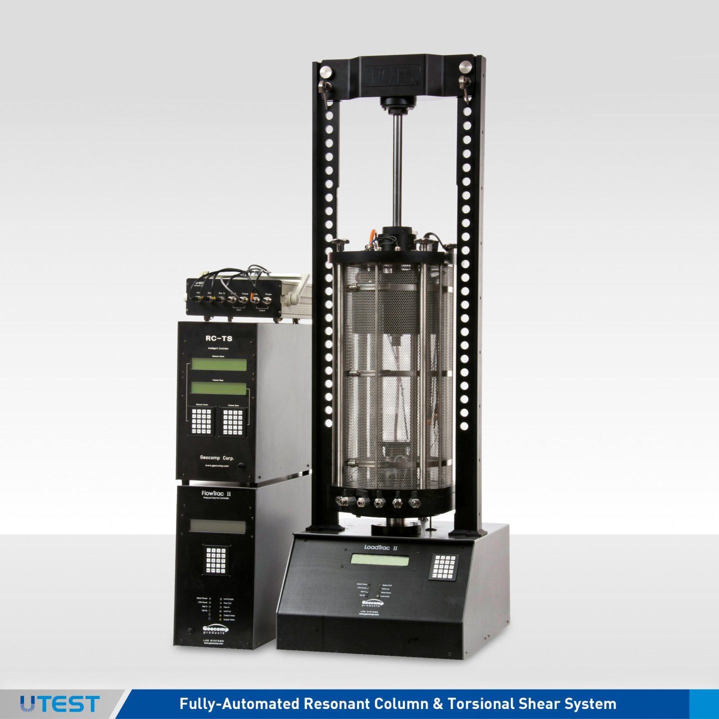
Geocomp's resonant column and torsional system is based on the Long-Tor Resonant Column Apparatus developed by Dr. Vincent P. Drnevich (patent 1974) at Purdue University. The term Long- Tor denotes the capability of the apparatus to vibrate specimens in ei- ther a longitudinal or torsional mode of vibration. The basic principle of the resonant column device is to excite one end of a confined cylindrical soil specimen in a fundamental mode of vibration by means of torsional or longitudinal excitation. Once the fundamental mode of resonance frequency is established, measurements are made of the resonance frequency and amplitude of vibration from which wave propagation velocities and strain amplitudes are calculated using the theory of elasticity. The shear modulus is determined from the derived velocity and the density of the specimen.
The resonant column test is used to measure shear modulus (G) and the damping ratio (D) at small shear strains. These values are a function of strain level. In the test, the shear strain level is increased step-by-step and the shear modulus and damping ratio are measured. The result of the test is a relationship between shear modulus and shear strain and between damping ratio and shear strain over a shear strain magnitude of 10-6 to 10-4 percent. Higher strain levels associated with extreme loads such as earthquakes and wave loading can not be achieved by resonant column testing using the electromagnetic force actuator to twist the specimen. For higher shear strains, our device can be switched to shearing in torsion. The torsional shear phase can be run to obtain shear modulus and damping up to shear strains of 10% depending on the stiffness of the soil. We can also subsequently shear the specimen along any stress path possible in a triaxial cell. Specimens can be consolidated isotropically or anisotropically.
A typical resonant column-torsional shear test on a specimen involves the following steps:
- Consolidation to the first stress condition
- Measurement of G and D versus shear strain at end of primary consolidation and at 3 times during secondary consolidation
- Consolidation to the second stress condition
- Measurement of G and D versus shear strain at end of primary consolidation and at 3 times during secondary consolidation
- Repeat above through final stress condition. Run torsional shear test to 10% strain to measure G and D for higher shear strain levels. Run triaxial compression test to measure shear strength of the specimen, drained or undrained.
Testing Capabilities
Geocomp's resonant column torsional shear testing system is a complete system capable of performing the following tests:
- Resonance in torsion.
- Damping Ratio in torsion.
- Torsional shear up to 2 Hz
- Triaxial or stress path after torsional shear
Geocomp RCTS turnkey system consists of the following:
- LoadTrac-II
- Two FlowTrac-II's
- Electro-Magnetic Drive System
- Torsional Shear System
- All built-in electronics and data acquisition
- Full automation through all phases of a test
Applicable Standards
- ASTM D4015
- ASTM D-4767
- AASHTO T-297
Technical Specifications
|
Motor |
Stepper motor with built-in controls |
|
Travel |
Built-in displacement transducer with 76 mm (3 in.) range and 0.0013 mm(0.00005 in) resolution |
|
Displacement |
Control from 0.00003 to 35 mm per minute (0.000001 to 1.3 in. per minute) |
|
Flow Range |
0.000006 to 3 cc per second |
|
Power |
110/220 V, 50/60 Hz, 1 phase |
|
|
Dimensions |
Weight (approx.) |
|
LoadTrac II |
464 x 546 x1206 mm ( 18 x 21.5 x 47.5 in. ) |
55 kg |
|
FlowTrac II |
203 x 406 x 470 mm (8 x 16 x 18.5 in.) |
14 kg |
Models
|
FlowTrac II Models |
|
|
FTII-250-nn |
250 cc capacity |
|
FTII-750-nn |
750 cc capacity |
|
|
Maximum pressure range for system: 1400 and 3500 kPa (200 and 500 psi) available (resolution of pressure will be 0.00005 times the range) |
|
LoadTrac II Models |
|
|
LTII-5,000 |
22 kN (5,000 lbs.) frame capacity |
|
LTII-10,000 |
45 kN (10,000 lbs.) frame capacity |
|
LTII-20,000 |
90 kN(20,000 lbs.) frame capacity |
Accessories
Triaxial cells to test samples up to 305mm (12.00 in.) diameter, membranes, porous stones and sample preparation accessories upon request.
72. Fully-Automated Resilient Modulus Unit
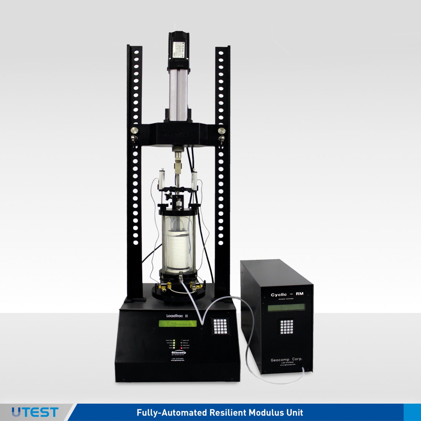
Product Code
LoadTrac II-RM
Geocomp's LoadTrac II Resilient Modulus unit fully automates resilient modulus tests on base/subbase/subgrade materials. The LoadTrac II meets or exceeds all specifications for Resilient Modulus Testing of Base/Subbase/Subgrade Materials by AASHTO T-294/T-307 and SHRP Protocol P46. It minimizes man time during testing and offers a versatile platform for performing additional geotechnical tests.
User Features and Benefits
ADDITIONAL TESTING CAPABILITIES
Geocomp's load frame does more than just Resilient Modulus testing. With software and accessories, the following tests can also be done:
- California Bearing Ratio
- Compression Testing of Weak Rocks and Cement Mixtures
- Constant Rate of Strain Consolidation Testing
- Cyclic Triaxial Testing
- Incremental consolidation
- Triaxial Testing
- Unconfined Compression.
FULLY AUTOMATED MINIMUM INTERVENTION ON YOUR PART
The LoadTrac II performs resilient modulus tests from beginning to end according to the latest AASHTO standards without human intervention.
APPLIES AN ACCURATE LOAD THROUGHOUT TESTING
Resilient modulus testing is a complicated test in which the stiffness of the sample changes with loading. Since the performance of cyclic loading systems depends on the stiffness of the sample, most systems fail to apply the correct load throughout the test. Our system uses real-time adjustment of a PID controller to adjust the system control parameters as the stiffness of the specimen changes. This feature permits our system to apply an accurate load from the beginning to the end of the test. Our system meets the rigid AASHTO specs for precision on loading to a haversine shape.
OPERATES IN A WINDOWS ENVIRONMENT
Training time is short, as most people are familiar with the Windows operat- ing environment. Users can configure a wide variety of graphical screens to display the test results including tabular and graphical display of channel values with time, graphical display of stresses, strains, displacements and resilient modulus values.
TEST DATA...THE WAY YOU WANT IT
Our system generates data in a variety of formats, so users get the most use out of the data. Options include:
- A complete final test report with all appropriate calculations on the data and constitutive relationships based on Publication
- No. FHWA-RD-97-083
- A text file of raw data and a text file of data in engineering units. Either can be easily loaded into a spreadsheet for further data analysis. Complete reporting software is included. This software creates reduced test results that are printed in tabular and graphical form instantly after testing. Results are available in any set of units, regardless of which set of units the test was run. Geocomp's Resilient Modulus Testing System is efficient and reliable. Many details of the test cell, instrumentation and loading system have been optimized thorough inhouse testing on a wide variety of materials utilizing over fifteen years of R&D experience. We continually improve our systems based on new technology and the experiences of our customers.
Technical Specifications
|
Cell Pressure |
Automatically applied, maintained and incremented with electro-pneumatic air pressure regulator |
|
Type Of Cyclic Loading |
Haversine pulse |
|
Cyclic Rate |
0.1 sec per pulse, 1 pulse per second and any slower values given by user |
|
Cyclic Loading |
• High performance custom linear actuator • 2.8kW peak, low inertia servo-drive system for fast response time. • High resolution feedback system for pre- cise and accurate control of load and speed. • 22 kN (5000lbs force) continuous load at speeds in excess of 200 mm (8") /sec • Self-contained and maintenance free • Single Phase 208 VAC/60Hz (US) / 220 VAC/50Hz (international) |
|
Options To End Test |
Maximum number of cycles Maximum strain |
|
Reporting Options |
• Shear stress versus pulse number • Axial strain versus pulse number • Resilient Modulus versus pulse number • Resilient Modulus versus deviator stress • Resilient Modulus versus confining stress • Automatic or user specified scaling on any of above plots • Plotting to monitor, printer, plotter, or file |
|
Test Cell |
Modified triaxial cell with sample preparation accessories |
|
Unit Systems |
U.S., English, metric and SI changeable at any time before, during and after test |
|
Sample Diameter |
70, 100, and 150 mm (2.8/4/6 inches) Custom sizes by special order |
|
Transducers |
Force: 2, 5,10 kN (500, 1000, 2500 lbf.) Displacement: 0.5 inch range, +25.4 mm (+1.00 in.) Cell pressure: 0-500 kPa (0-70 psi) |
|
System Requirements |
System is delivered complete to perform tests, store data, reduce data and report the test results. System will be calibrated and ready to begin testing immediately after installation. |
|
Documentation |
Full documentation and user's manuals are provided. HELP screens are available at every point in all software |
73. Fully-Automated Direct Residual Shear System
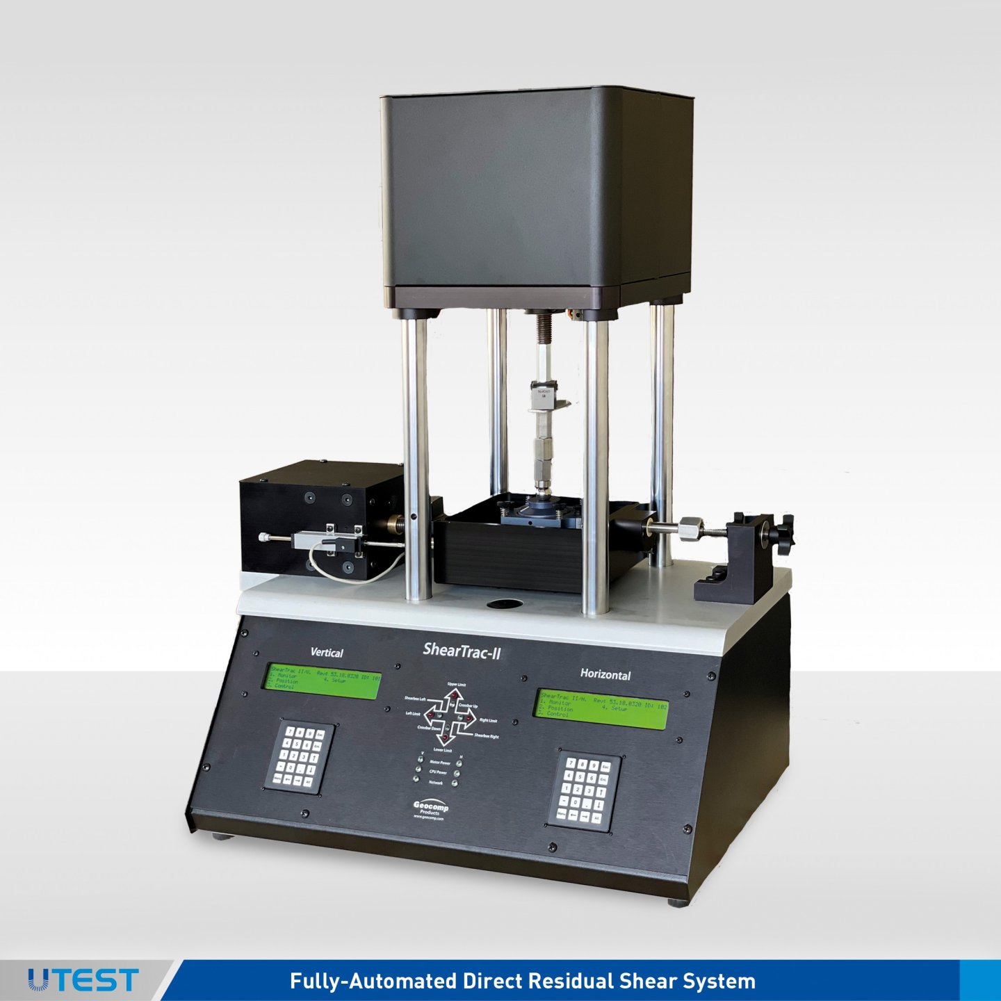
Product Code
ShearTrac II
The ShearTrac II system is capable of performing the consolidation and shearing phases of a standard direct shear and residual shear test under full automatic control. The system consists of a computer-controlled unit that utilizes microstepper motors to apply the vertical and horizontal loads to the soil specimen. Versions of the unit are available to produce vertical and horizontal loads up to 10 kN (2000 lbs.).
The system is capable of running a consolidation phase for up to 32 increments automatically. Horizontal shearing can be applied at a specified rate of deformation or at a specified rate of horizontal force change, or at a specified set of force steps of a specified duration. The system is capable of displaying the current status of a test and graphically portraying the progress of the test in real time. The system includes the capability for the operator to alter the test process and conditions at any stage of the test. The system is also capable of performing repeated direct shear tests to determine residual strength based on a specified number of repeated cycles. The system comes complete with hardware and software for recording all test input data and settings of selected test parameters, performing standard engineering calculations on the data, and producing graphically plotted and printed output in the standard Corps format.
Applicable Test Standards
- ASTM D3080/T236 Direct Shear testing of soils under Consolidated Drained Conditions.
User Benefits
- Choose load capacity to fit user needs up to 10kN (2,000 lbs.)
- Total automation, control, data collection and reporting of test results
- Prepare tables and plots of report quality within minutes of completing a test
- Geo-NET compatibility lets unit be accessed and controlled over a computer network
- Generate columns of data for easy reduction using your own spreadsheet software
- Accurate displacement rate control from 0.00003 to15 mm per minute (0.000001 to 0.6 in. per minute)
- Full automation of residual shear testing
- Stand alone through front keypad and LCD menu capability
Technical Specifications
|
Capacity |
Up to 10 kN (2,000 lbs.) |
|
Vertical Motor |
Stepper motor with built-in controls for vertical load |
|
Horizontal Mot. |
Stepper motor with built-in controls for horizontal load |
|
Speed Range |
0.00003 to 15 mm per min. (0.000001 to 0.6 in per minute |
|
Vertical Travel |
25.45 mm (1.00 in.) resolved to 0.0013 mm (0.00005 inches) |
|
Horizontal Travel |
±12.5 mm (±0.50 in.) resolved to 0.0013 mm (0.00005 inches) |
|
Power |
110/220 V, 50/60 Hz, 1phase |
|
ShearTrac II |
Load Capacity |
|
ST-1000 |
4.4kN(1000lb.) |
Accessories
- ShearTrac II accessories including ShearTrac II box to test square or round samples up to 101 mm (4 in.) dimension/ diameter,includes top and bottom porous stones.
- Geo-NET-PC Network card and cable to link ShearTrac II to PC.
- SHEAR Software package to automatically run and report direct /residual shear test on ShearTrac II.
|
Dimensions |
228 mm x 560 mm x 762 mm (9 in. x 22 in. x 30 in.) |
|
Weight (approx.) |
63 kg (140 lbs.) |
74. Fully-Automated Direct Simple Shear System
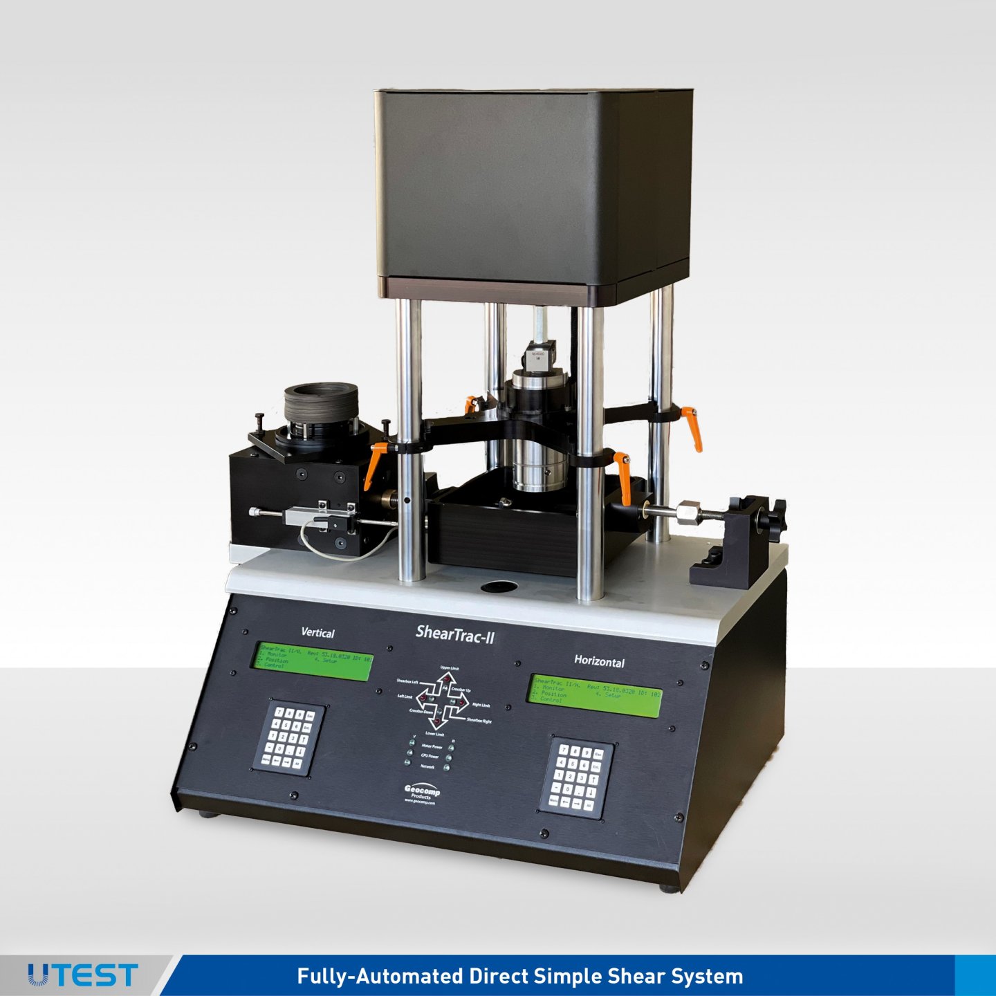
ShearTrac II-DSS
The ShearTrac II-DSS system is a universal shear system capable of performing the consolidation and shear phases of a direct simple shear test under full automatic control.
The direct simple shear device is a way to measure undrained shear strength of soils that reflects the average shear strength mobilized in the field during failure of embankments on soft soil foundations and deep excavations in clay The DSS test generates a fairly homogeneous state of shear stress throughout the specimen, which provides initial stress condition, stress path, and deformation configuration that models numerous field loading conditions more closely than any other test systems such as triaxial. The system consists of a computer controlled unit that utilizes micro-stepper motors to apply the vertical and horizontal loads to the soil specimen.
The system is capable of running a consolidation phase for up to 32 increments automatically. Horizontal shearing can be applied at a specified rate of deformation or at a specified rate of horizontal force change. The constant volume condition during the shear is maintained through a closed loop computer control with the vertical displacement sensor as the feedback. The system is capable of displaying the current status of a test and graphically portraying the progress of the test in real time. The system includes the capability for the operator to alter the test process and conditions at any stage of the test.
Applicable Test Standards
- ASTM D 6528 Consolidated Undrained Direct Simple Shear Testing of Cohesive Soils
- ASTM D2435/T216 One-Dimensional Consolidation Properties of Soils
User Benefits
- Choose load capacity to fit user needs up to 10kN (2,000 lbs.)
- Total automation, control, data collection and reporting of test results
- Prepare tables and plots of report quality within minutes of completing a test
- Geo-NET compatibility lets unit be accessed and controlled over a computer network
- Generate columns of data for easy reduction using your own spreadsheet software
- Accurate displacement rate control from 0.00003 to15 mm per minute (0.000001 to 0.6 in. per minute)
- Stand alone through front keypad and LCD menu capability
Accessories
- ShearTrac II-DSS accessories includes shear box to test round samples up to 100 mm (4 in.) diameter, top and bottom ® porous stones with Teflon coated stacked rings.
- Geo-NET-PC Network card and cable to link ShearTrac II to PC.
- DSS Software package to automatically run and report direct simple shear tests.
Models
|
ST-DSS-500 |
2.5 kN (500 lbs.) |
|
ST-DSS-1000 |
5 kN (1000 lbs.) |
|
ST-DSS-2000 |
10 kN (2000 lbs.) |
Technical Specifications
|
Capacity |
Up to 11 kN (2,500 lbs.) |
|
Vertical Motor |
Stepper motor with built-in controls for vertical load |
|
Horizontal Mot. |
Stepper motor with built-in controls for horizontal load |
|
Speed Range |
0.00003 to 15 mm per min. (0.000001 to 0.6 in per minute |
|
Vertical Traver |
12.5 mm (0.5 in.) resolved to 0.0013 mm (0.00005 inches) |
|
Horizontal Travel |
±12.5 mm (±0.50 in.) resolved to 0.0013 mm (0.00005 inches) |
|
Power |
110/220 V, 50/60 Hz, 1 phase |
75. Fully-Automated Cyclic Simple Shear System
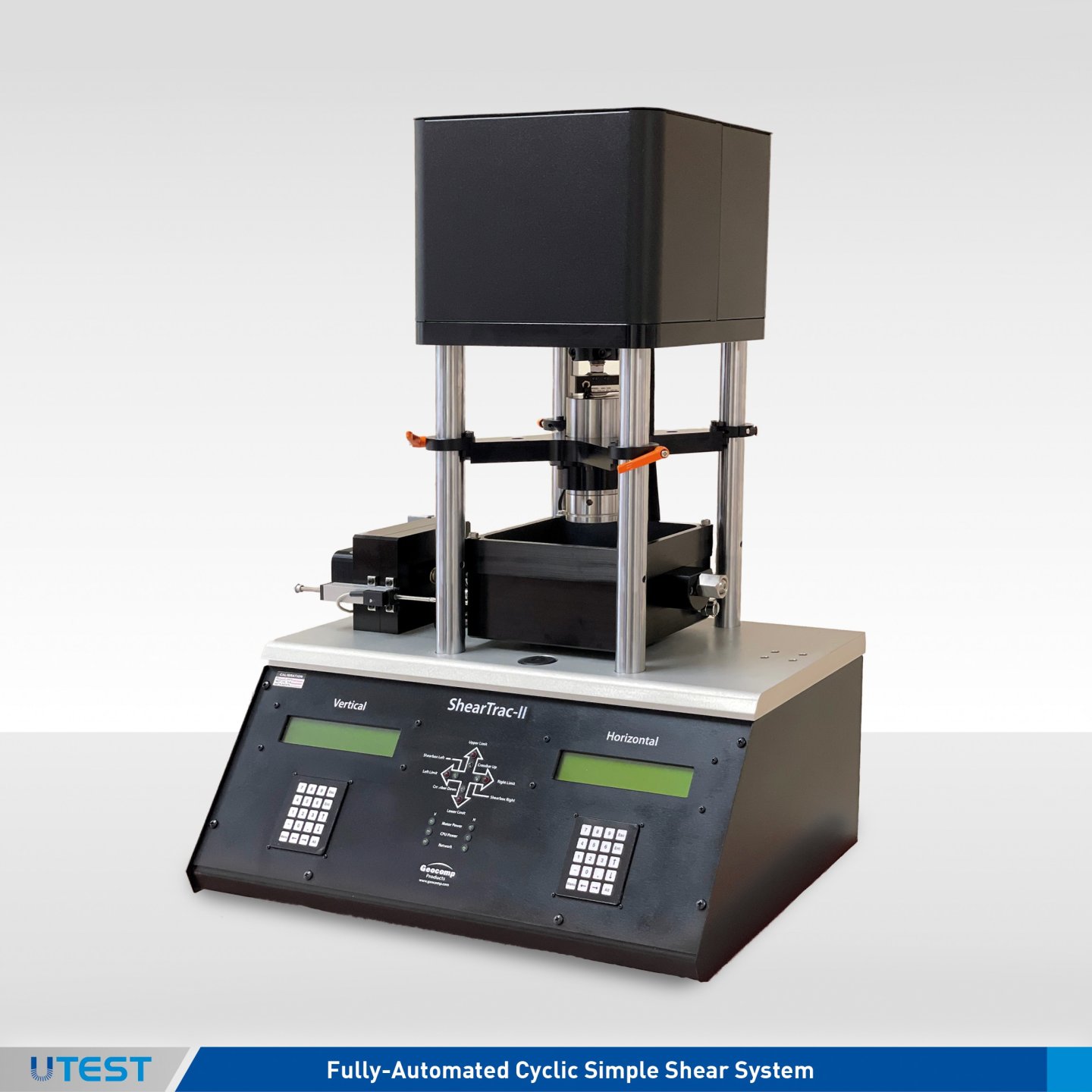
Product Code
ShearTrac II-DSS CY
The ShearTrac II-DSS CY system is a universal shear system capable of performing the consolidation, static and cyclic direct simple shear phases under full automatic control. This system is of the type developed at NGI in the mid 1960's. The DSS test generates a fairly homogeneous state of shear stress throughout the specimen, which provides initial stress condition, stress path, and deformation configuration that models numerous field loading conditions more closely than any other strength tests such as triaxial. The system consists of a computer controlled unit that utilizes micro-stepper motors to apply the vertical and horizontal loads to the soil specimen.
The system is capable of running a consolidation phase for up to 32 increments automatically. Stress controlled cyclic can be applied up to a frequency of 1 Hz that can be followed by simple shearing at a specified rate of deformation or force. The constant volume condition is maintained through a closed loop computer control with the vertical displacement sensor as the feed back. The system is capable of displaying the current status of a test and graphically portraying the progress of the test in real time. The system includes the capability for the operator to alter the test process and conditions at any stage of the test.
The system comes complete with hardware and software for recording all test input data and settings of selected test parameters, performing standard engineering calculations on the data, and producing graphically plotted and printed output.
Applicable Test Standards
- ASTM D 6528 Consolidated Undrained Direct Simple Shear Testing of Cohesive Soils
- ASTM D2435/T216 One-Dimensional Consolidation Properties of Soils
User Benefits
- Choose load capacity to fit user needs up to 5kN (1,000 lbs.)
- Total automation, control, data collection and reporting of test results
- Prepare tables and plots of report quality within minutes of completing a test
- Geo-NET compatibility lets unit be accessed and controlled over a computer network
- Generate columns of data for easy reduction using your own spreadsheet software
- Accurate displacement rate control from 0.00003 to15 mm per minute (0.000001 to 0.6 in. per minute)
- Select number of data points logged per cycle form 10 to 500 readings per second
- Manual control capability through front keypad and LCD menus
- Versatile system
SOIL SPECIMEN DIMENSIONS:
Diameter: 2.5 in. (63.5 mm) up to 4.0 in.(101.5 mm)
|
Dimensions |
228 mm x 560 mm x 762 mm (9 in. x 22 in. x 30 in.) |
|
Weight (approx.) |
63 kg (140 lbs.) |
|
Accessories |
Geo-NET-PC Network/Communication card to link ShearTrac II-DSS to PC. Teflon- coated stacked rings, and stainless steel trimming ring |
|
Software Module |
Cyclic DSS Software package to automatically run and edit cyclic and static direct simple shear test |
|
Options |
Direct/Residual Shear, Incremental Consolidation, and CRC options available upon request |
Technical Specifications
|
Capacity |
Up to 10 kN (2,000 lbs.) |
|
Vertical Force |
Stepper motor with built-in controls for vertical load and displacement |
|
Horizontal Force |
Stepper motor with built-in controls for horizontal load and displacement |
|
Speed Range |
0.00003 to 15 mm per min. (0.000001 to 0.6 in per minute |
|
Frequency Range |
Up to 1 Hz. |
|
Vertical Travel |
25.45 mm (1.00 in.) resolved to 0.0013 mm (0.00005 inches) |
|
Horizontal Travel |
±12.5 mm (±0.50 in.) resolved to 0.0013 mm (0.00005 inches) |
|
Power |
Single Phase 208 VAC/60Hz (US) / 220 VAC/50Hz (international) |
76. Fully-Automated Sheartrac III System
Product Code
ShearTrac III
The ShearTrac IIITM system is capable of performing the consolidation and shear- ing phases of a 305 mm x 305 mm (12 x 12 in. by 200mm(8.0 in) height direct shear test under automatic control for soils and geosynthetics (geomembrane, geotextile, GCL, geogrid, etc.) as well as for deter- mining the interface frictional properties of soil and geosynthetics, and internal friction of GCLs.
The system consists of a computer con- trolled unit that utilizes a micro stepper motor to apply the horizontal loads. Ver- sions of the unit are available to test loads up to 50 kN (10,000 lbs). Builtin elec- tronics control test and display data in real time. The system is capable of applying a constant rate of strain or stress at any displacement rate up to 15mm (0.6 inch) per minute. The computer controlled program runs under latest Windows. It includes the capability to display the current status of latest and graphically portray the progress of the test in real time. The system also includes the capa- bility for the operator to alter the test process and conditions at any stage during the test.
This is a turnkey system that includes hardware and software for recording all test input data and settings of selected test parameters, performing standard engineering calculations on the data, and producing graphically plotted and printed output in the standard Corps format, in accordance with ASTM D5321, D6243 and BS 1377 standards.
Applicable Test Standards
- ASTM D-5321 and D-6243
- ASTM 3080/T236
- BS 1377
Features / Benefits
- Built-in end clamps for geosynthetics testing
- Optional grip plates for true internal friction determination for GCLs
- Linear bearings for minimum horizontal friction
- Two sets of limit switches to prevent over traveling
- Built-in 4-channel data acquisition with 16-bit resolution
- Two LCD display
- Two displacement transducers with 100 mm (4.00 in.) range and 0.002 mm (0.00008 in.) resolution
- Two universal shear web type load cells
- Accurate displacement rate control from 0.00003 to 10 mm per minute (0.000001 to 0.4 in. per minute)
- Built-in electronic controls for automatic display of data and control of test
- Windows XP, or Vista, 7 friendly user interface
- Fully incremental consolidation test capability
Technical Specifications
|
Capacity |
50 kN (10,500 lbs.) |
|
Vertical Motor |
Stepper motor with built-in controls for vertical load |
|
Horizontal Mot. |
Stepper motor with built-in controls for horizontal load |
|
Speed Range |
90 mm (3.5 in.) resolved to 0.002 mm (0.00008 inches) |
|
Vertical Travel |
90 mm (3.5 in.) resolved to 0.002 mm (0.00008 inches) |
|
Horizontal Travel |
90 mm (3.5 in.) resolved to 0.002 mm (0.00008 inches) |
|
Power |
110/220 V, 50/60 Hz, 1phase |
Models
|
ST-10000 |
50 kN (10,000 lbs.) frame capacity in both directions. |
Accessories
|
Geo-NETTM-PC |
Network card and cable to link ShearTrac III to PC |
|
Shear |
Software package to automatically run consolidation and direct shear test on ShearTrac III |
|
Shear.report |
Editing/reporting software package |
|
Gripping Plates |
Optional for GCL testing |