UTEST ASPHALT TESTING
1. Reflux Extraction Test Set

Product Code
|
UTAS-0013 |
Reflux Extraction Test Set 1000 g, 220-240 V 50-60 Hz |
|
UTAS-0014 |
Reflux Extractor Jar 1000 g |
|
UTAS-0015 |
Reflux Extractor Condenser 1000 g |
|
UTAS-0016 |
Reflux Extractor Conical Wire Screen 500 g |
|
UTGH-1830 |
Iron Wire Gauze 120x120mm |
|
UTAS-0020 |
Reflux Extraction Test Set 4000 g, 220-240 V 50-60 Hz |
|
UTAS-0021 |
Reflux Extractor Jar 4000 g |
|
UTAS-0022 |
Reflux Extractor Condenser 4000 g |
|
UTAS-0023 |
Reflux Extractor Conical Wire Screen 2000 g |
|
UTAS-0024 |
Filter Paper Ø300mm (50 pcs./pack) for UTAS-0013 |
|
UTAS-0025 |
Filter Paper Ø 400mm (50 pcs./pack) for and UTAS-0020 |
|
UTGH-1835 |
Iron Wire Gauze 160x160mm |
Standards
ASTM D2172
The Reflux Extractor is used for the quantitative determination of bitumen in hot-mixed paving mixtures and pavement samples. The bitumen content is calculated by difference from the weight of extracted aggregates, moisture content and ash from an aliquot part of the extract.
The Reflux Extraction Test Sets are supplied complete with;
- Cylindrical Glass Extractor Jar
- Two Wire Mesh Cones with Interlocking Frames
- Water Condenser with Inlet/Outlet Tubes
- Filter Paper, 50 pcs./pack
- Hot Plate
- Iron Wire Gauze (UTGH-1830 with UTAS-0013, UTGH-1835 with UTAS-0020)
|
Dimensions |
UTAS-0013 |
200x200x800 mm |
|
UTAS-0020 |
330x600x330 mm |
|
|
Weight (approx.) |
UTAS-0013 |
7 kg |
|
UTAS-0020 |
8 kg |
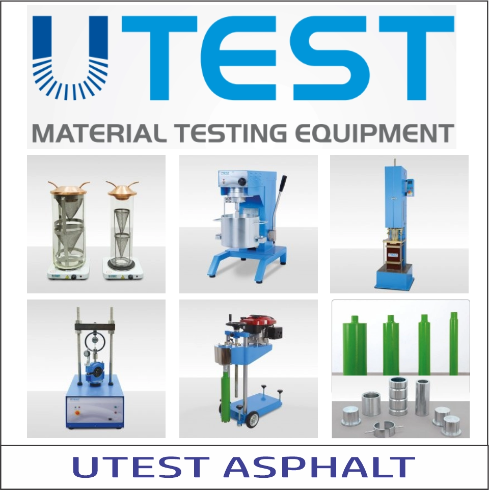
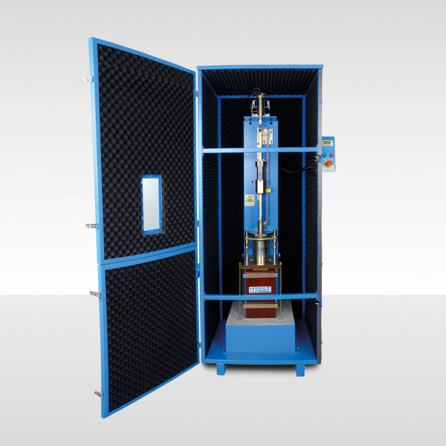
2. Centrifuge Extractor
Product Code
|
UTAS-0030 |
Centrifuge Extractor 1500 g |
|
UTAS-0031 |
Filter Paper 250 mm Outer dia. 45 mm Inner dia. for UTAS-0030 (100 pcs/Pack) |
|
UTAS-0032 |
Rotating Bowl and Cover for UTAS-0030 |
|
UTAS-0035 |
Centrifuge Extractor 3000 g capacity, 220-240 V 50-60 Hz |
|
UTAS-0036 |
Filter Paper 295 mm Outer dia. 45 mm Inner dia. for UTAS-0035(100 pcs / Pack) |
|
UTAS-0037 |
Rotating Bowl and Cover for UTAS-0035 |
|
Models for 220-240V 50-60 Hz, 1 ph. |
UTAS-0030 |
UTAS-0035 |
|
Models for 110-120V 60 Hz, 1 ph. |
UTAS-0030-N |
UTAS-0035-N |
Standards
EN 12697-1 Clause B.1.5; AASHTO T164 A; ASTM D2172 A
The Centrifuges are used for the determination of the bitumen percentage in bituminous mixtures. All models comprise a removable precision-machined rotor bowl housed in a cylindrical aluminum box. The bowl is driven by an electric motor fitted with an AC drive (inverter) with the double function of speed control up to 3600 rpm regardless of the frequency (50 or 60 Hz) and electrical breaking. The centrifuge can be set for the automatic speed ramp up to 3600 rpm and will stop in 10-15 seconds.
The cover is precisely machined and fitted with a solvent resistant gasket to avoid leakages.
The control panel includes: Start/Stop button and speed control knob.
Filter paper UTAS-0031 for UTAS-0030 or Filter paper UTAS-0036 for UTAS-0035 should be ordered seperately
The Centrifuge Extractor is supplied complete with;
- Bowl and Cover

UTAS-0031 UTAS-0032 UTAS-0036 UTAS-0037
|
Dimensions |
370x550x550 mm |
|
Weight (approx.) |
40 kg (for both models) |
|
Power |
370W (for both models) |
3. Asphalt Binder Analyzer (ABA)

Product Code
|
UTAS-0060 |
Asphalt Binder Analyzer (ABA) by the Ignation Method |
|
UTAS-0061 |
Spare Basket and Tray Set |
|
UTAS-0062 |
Cooling Cage |
|
UTAS-0065 |
Metal Stand for UTAS-0060 |
|
Models for 380V, 50 Hz, 3 ph. |
UTAS-0060-C |
Models for 240 V, 60 Hz, 2 ph. |
UTAS-0060-V |
|
Models for 208 V, 60 Hz, 3 ph. |
UTAS-0060-NC |
Models for 220-240V 50-60 Hz, 1 ph |
UTAS-0060 |
Standards
EN 12697-39; AASHTO TP53, T308; ASTM D6307
The UTEST ABA Asphalt Binder Analyzer is used to determine the binder content of hot mix asphalt/bituminous mixtures by the method of loss on ignition. The system combines a sophisticated furnace and weighing system to continuously measure the weight loss of a bituminous mixture during combustion and automatically calculates its binder content at the end of the test.
Supplied complete with 2 specimen baskets with a safety cover, a carrying tray, a fork to catch the tray, and 3m metal exhaust pipe. The Metal Stand (UTAS-0065), the cooling cage (UTAS-0062) and if the tests are to be performed consecutively without waiting for cooling, the Spare Basket and Tray Set (UTAS-0061) shoud be ordered seperately.
UTAS-0061 Spare Basket and Tray Set consists of 2 pcs. basket (one has a safety cover) and a carrying tray.
OVEN AND AFTERBURNER
- High efficiency heating system with afterburner chamber for a total combustion of exhaust fumes to minimize emissions to conform with EU Directives
- Sample size up to 4500 g for more representative test results
- Maximum power rating is 10 kW
HARDWARE
- 16 bit microprocessor with one CPU card controlling test data display, temperature, database and internal functions
- Large permanent memory to store test results
- On board 40 column serial printer
- Weighing system 15000 g capacity, 0.1 g resolution and detecting mass variations of ± 0,1 g
- PID closed loop thermoregulation for both oven and afterburner chamber
- 800 ºC Afterburner 540 ºC oven set temperature according to standard
- TFT touchscreen with 800x480 resolution and 65000 colors
FIRMWARE
- Bidirectional real time communication with the weighing system
- Test setting menu with physical and descriptive sample parameters (initial weight, weight loss percentage, correction factor)
- Calibration menu to check and set the temperature and weight calibration for possible manual control of the test performance
- Test performance menu with simultaneous display of all the test data
- Internal memory for up to 100 tests
SAFETY FEATURES
- Automatic door locking after 150 ºC
- Automatic monitoring of closed door before test start

The UTEST ABA Asphalt Binder Analyzer is supplied complete with;
- Two Specimen Basket with a Safety Cover
- A Carrying Tray
- Carrying Fork
- 3m Metal Exhaust Pipe

|
Dimensions |
670x1140x1230 mm |
|
Weight (approx.) |
135 kg |
|
Power |
10 kW |
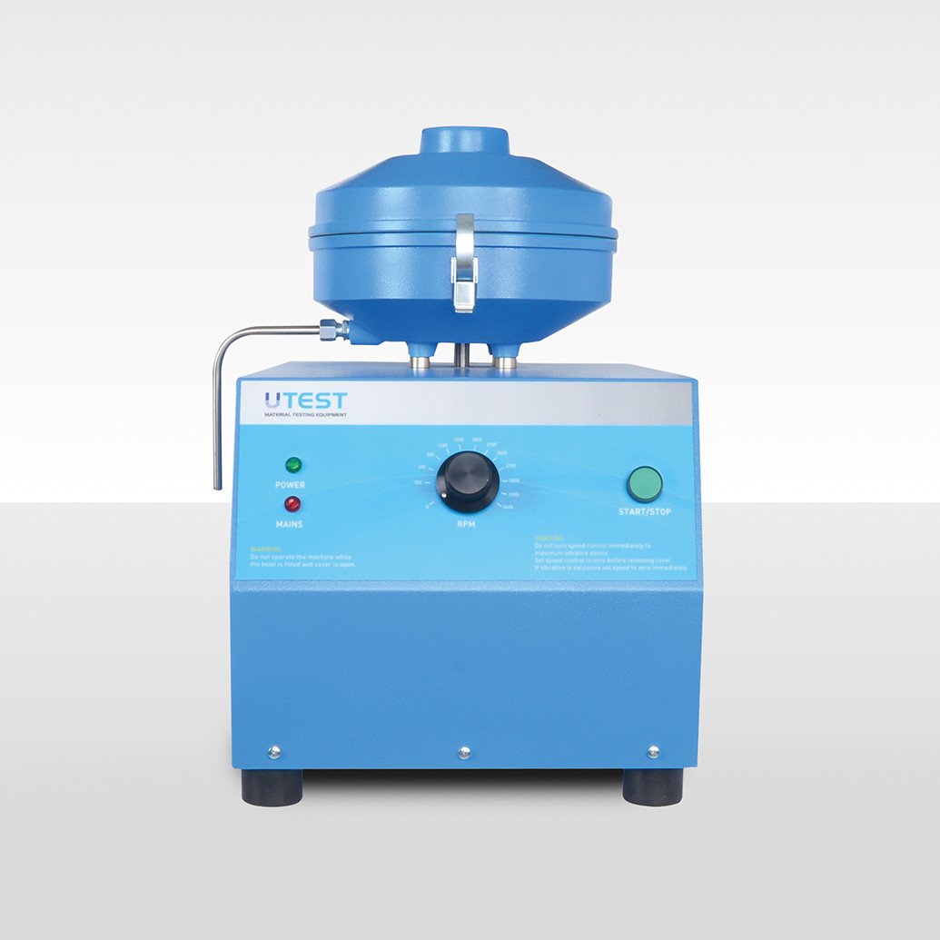
4. Solvent Recovery Unit
Product Code
|
UTAS-0091 |
Solvent Recovery Unit 10 lt/h Capacity |
|
Models for 220-240V 50-60 Hz, 1 ph. |
UTAS-0091 |
|
Models for 110-120V 60 Hz, 1 ph. |
UTAS-0091-N |
Non-flammable solvent liquids used for the binder extraction test can be successfully recovered using the UTAS-0091 Solvent Recovery Unit.
The recovery unit consists of two stainless steel chambers, one for the dirty used solvent and the other for the cleaned recovered solvent.
Solvent in the left-hand side chamber is distilled by an electrical heater and then passes through a water cooling system and drops into the second chamber ready for re-use.
A temperature switch automatically stops the heating elements when the recovery process is completed.
The unit is supplied complete with 3 m plastic tubing, tube clamps, sieve insert 0.6 mm opening and one lid.

The Solvent Recovery Unit is supplied complete with;
- Plastic Tubing, 3 m
- Tube Clamps
- Sieve Insert, 0.6 mm
- Lid
|
Dimensions |
360x420x600 mm |
|
Weight (approx.) |
21 kg |
|
Power |
1200 W |
|
Max. Tempature |
150°C |
5. Vacuum Pyknometer (Yale Pycnometer) for Rice Test
![]()
Product Code
|
UTAS-0093 |
Vacuum Pyknometer (Yale Pycnometer) for Rice Test 4.3L, Aluminium |
|
UTAS-0094 |
Large Size Heavy Duty Vacuum Pyknometer (Yale Pycnometer) for Rice Test, 10 L |
|
UTG-0310 |
Vibro-Deaerator, Timer Controlled |
|
UTGE-3505 |
Vacuum Pump, 51 lt/min Capacity, 220-240 V 50-60 Hz, 1ph |
|
UTGE-3530 |
Dual Stage Vacuum Pump 128 lt/min Capacity, 220-240 V 50-60 Hz, 1ph |
|
UTGE-3552 |
Vacuum Gauge, Analog, -100 kPa, 1 kPa graduated, dia: Ø 63 mm |
|
UTGE-3570 |
Air Drying Unit/ Water Trap, Vacuum Type |
|
UTGG-2016 |
Filter Flask for Vacuum, 2000 ml |
|
Models for 220-240V 50-60 Hz, 1 ph. |
UTG-0310 |
|
Models for 110-120V 60 Hz, 1 ph. |
UTG-0310-N |
Standards
ASTM D2041; EN 12697-5
The Vacuum Pyknometers (Yale Pyknometer) are used for determining the theoretical maximum specific gravity and density of compacted or non-compacted bituminous paving mixtures (voidless mass).Percent air voids in compacted bituminous mixtures and the amount of bitumen absorbed by the aggregates can also be calculated with the test.
UTAS-0093 consists of a 4,3 liter aluminium container, a transparent vacuum lid a aluminium volumetric lid.
UTAS-0094 consists of a 10 liter transparent plastic container, a transparent plastic vacuum lid and a transparent plastic plate.
To complete the test, vibro-deairator(UTG-0130), vacuum pump, vacuum gauge(UTGE-3552), 2 pcs. filter flask (UTGG-2016) or air drying unit / water trap (UTGE-3570) should be ordered separately, in addition to UTAS-0093 or UTAS-0094.
Vacuum Pumps are supplied with 3m plastic tube (Ø8mm OD, - UTGP-1440)) and an auto-nipple.
UTGE-3552 Vacuum gauge, analog, scale range (-100/0 kPa), accuracy (1.0 % of scale range), 1 kPa graduated, Ø63 mm. Supplied with a valve, 4-way dispenser muffler and. its hanger.
|
Product Code |
External Dimensions |
Weight (approx.) |
|
UTAS-0093 |
210x210x350 cm |
7 kg |
|
UTAS-0094 |
300x300x450 cm |
7 kg |
|
UTG-0310 |
500x500x320 cm |
90 kg |
|
UTGE-3505 |
290x290x220 cm |
7 kg |
|
UTGE-3530 |
340x140x240 cm |
10 kg |
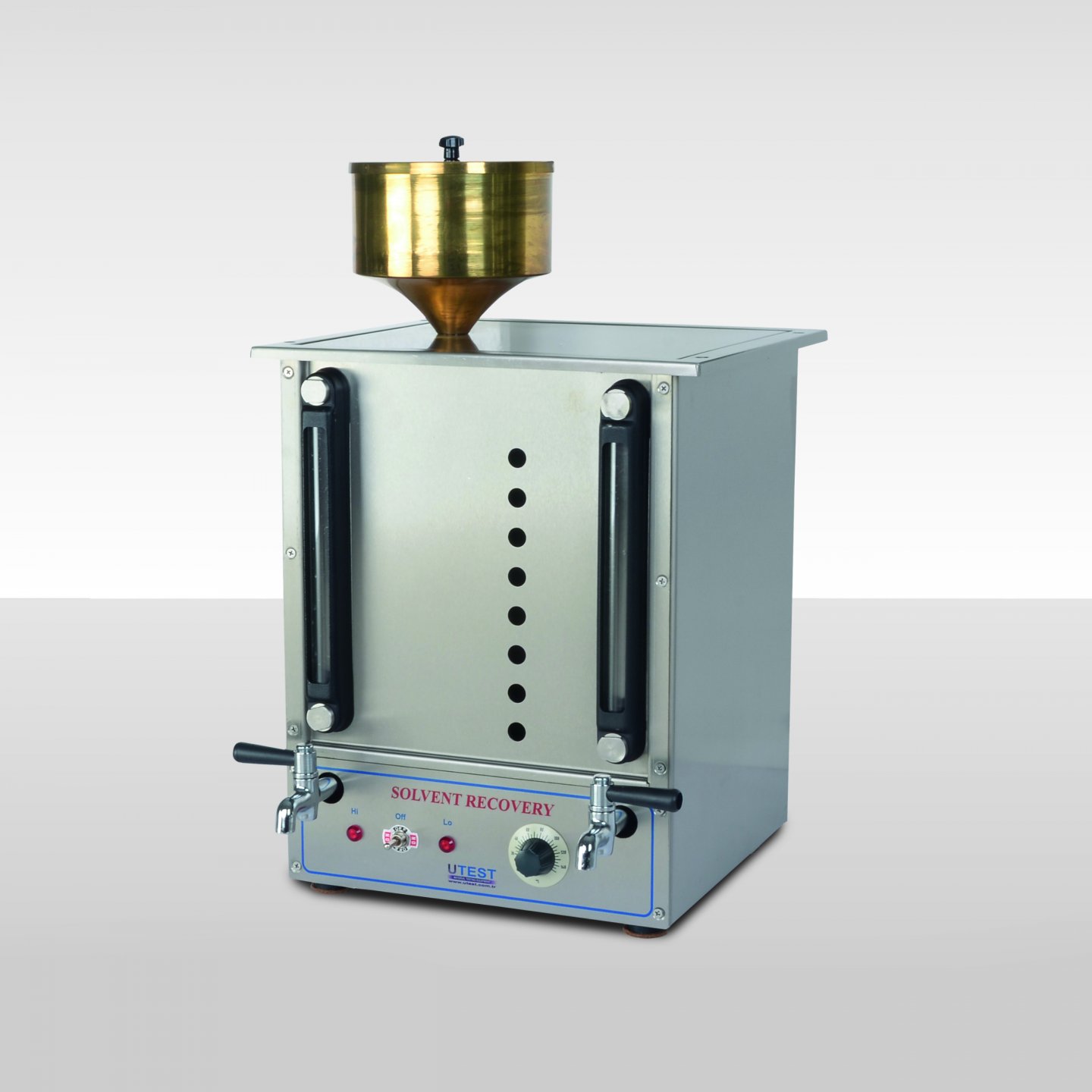
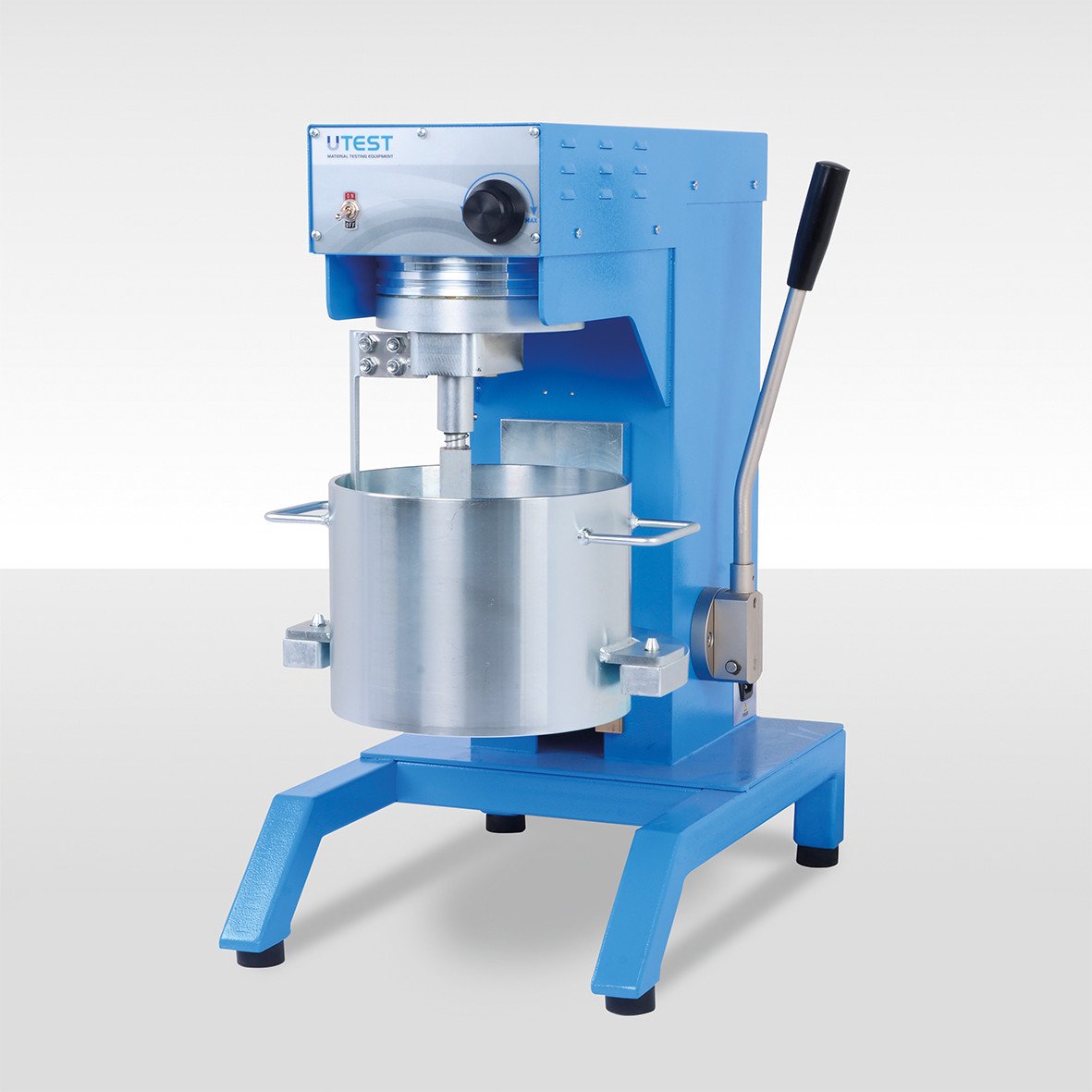
6. Laboratory Mixer 10 L

Product Code
|
UTG-0130 |
Laboratory Mixer 10 L |
|
UTAS-0187 |
Heating Mantle for UTG-0130 |
|
UTG-0131 |
Spare Bowl for UTG-0130 |
|
UTG-0132 |
Spare Whisk for UTG-0130 |
|
Models for 220-240V 50-60 Hz, 1 ph. |
UTG-0130 |
UTAS-0187 |
|
Models for 110-120V 60 Hz, 1 ph. |
UTG-0130-N |
UTAS-0187-N |
Standards
EN 12697-35
The UTG-0130 10 litre capacity Laboratory Mixer is designed for mixing of soil and asphalt samples to be used for mechanical tests such as compaction, indirect tensile, Marshall etc. The mixing head rotates at speeds of 10 to 240 r.p.m. and the whisk from 20 to 480 r.p.m. The user can adjust rotation speed between given values easily by using a control knob fitted to the front panel.
The bituminous mixture must be prepared at the prescribed temperature according to the EN standard. For this reason the mixer can be equipped with thermostatically controlled heater.
The Heating Mantle (Isomantle heater) has a digital thermostatic controller and used for heating the bituminous mixtures in the UTG-0130 up to 150°C. The Isomantle heater is supplied complete with PT100 temperature sensor.
Heating Mantle should be ordered separately.

UTAS-0187
The Laboratory Mixer is supplied complete with;
- Bowl,10 lt Capacity Stainless Steel
- Mixing Whisk

UTG-0132 UTG-0131
|
|
UTG-0130 |
UTAS-0187 |
|
Dimensions |
600x620x700 mm |
310x380x200 mm |
|
Weight (approx.) |
65 kg |
6 kg |
|
Power |
550 W |
600 W |
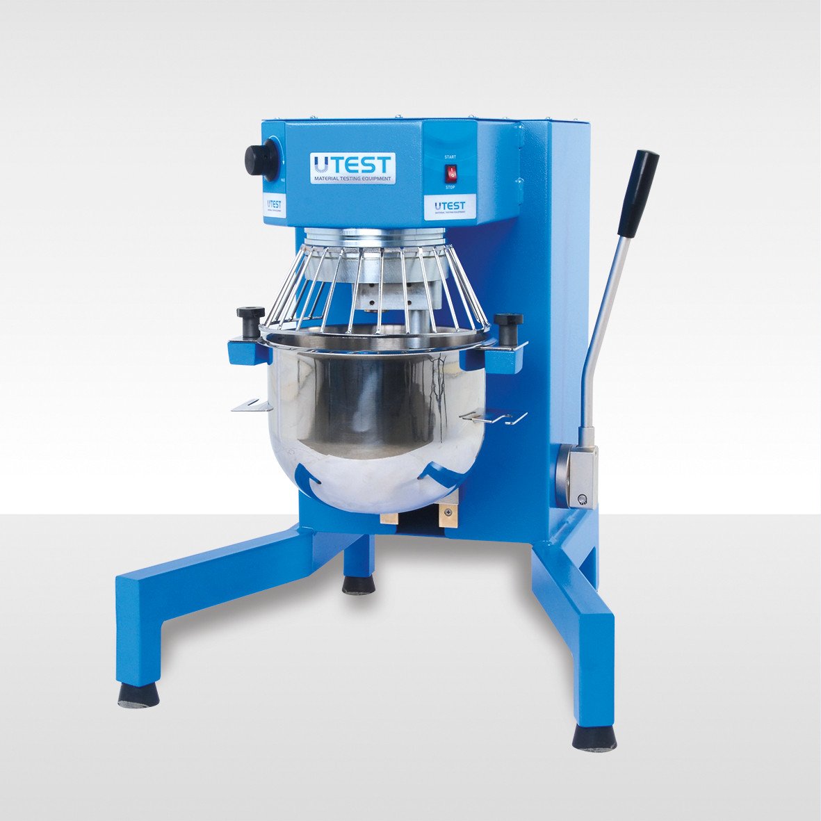
7. Laboratory Mixer 7.5 L
Product Code
|
UTAS-0195 |
Asphalt Mixer, 7.5 L |
|
UTAS-0196 |
Spare Mixing Bowl, 7.5 L, for UTAS-0195 |
|
UTAS-0197 |
Spare Mixing Whisk, for UTAS-0195 |
|
Models for 220-240V 50-60 Hz, 1 ph. |
UTAS -0195 |
|
Models for 110-120V 60 Hz, 1 ph. |
UTAS 0195-N |
Standards
EN 12697-35
The mixer has a capacity of 7.5 liters and is designed for mixing of asphalt samples to be used for mechanical tests such as compaction, indirect tensile, and Marshall. The mixer does not contain a heater.
The Laboratory Mixer is supplied complete with;
- Bowl, 7,5 lt Capacity, 5,5 kg, Stainless Steel
- Mixing Whisk

UTAS-0196 UTAS-0197
|
Dimensions |
370x570x700 mm |
|
Weight (approx.) |
70 kg |
|
Power |
550 W |
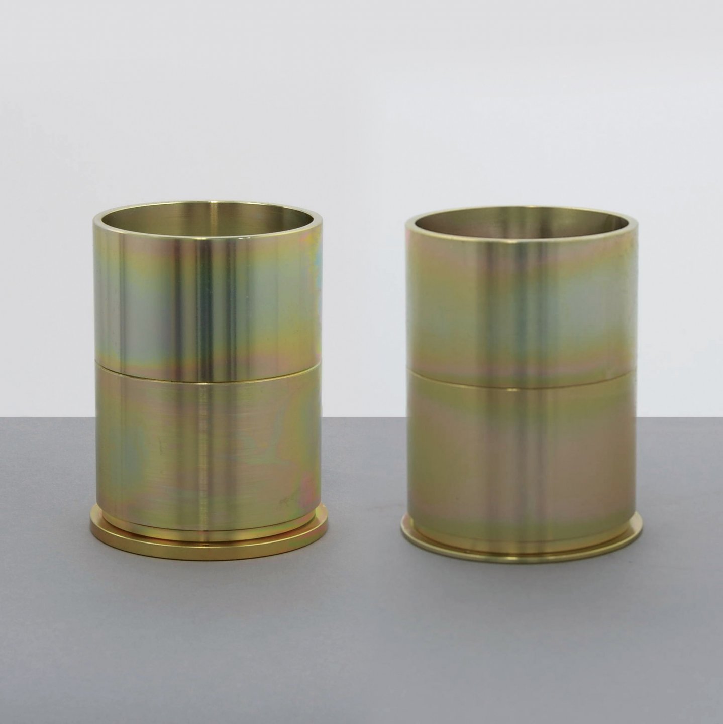
8. Marshall Compaction Mould
Product Code
|
UTAS-0641E |
Marshall Compaction Mould for Impact Compactor with Wooden Pedestal, EN, 101.6 mm |
|
UTAS-0642E |
Base Plate for UTAS-0641E |
|
UTAS-0643 |
Collar for UTAS-0641E and UTAS-0641A |
|
UTAS-0644 |
Mould Body for UTAS-0641E and UTAS-0641A |
|
UTAS-0641A |
Marshall Compaction Mould ASTM 4” |
|
UTAS-0642A |
Base Plate for UTAS-0641A |
|
UTAS-0646A |
Marshall Compaction Mould ASTM 6” |
|
UTAS-0664 |
Marshall Storage Plate for 6 pcs. for 4” (101.6mm) specimens |
Standards
EN 12697-30; ASTM D1559, D6926, D5581; AASHTO T245
The Marshall Compaction Moulds are used to produce the Marshall specimens with automatic or manual compactors. The moulds are manufactured using galvanized steel. UTAS-0664 Marshall Storage Plate is designed to store 6 pcs , 4” diameter Marshall specimens.
UTAS-0641E, UTAS-0641A and UTAS-0646A compaction moulds comprise a base plate, a mould body and a collar.


UTAS-0641E UTAS-0642A

UTAS-0664
|
|
Dimensions |
Weight (approx.) |
|
UTAS-0641E |
Ø120x170 mm |
3,5 kg |
|
UTAS-0641A |
Ø120x170 mm |
3,5 kg |
|
UTAS-0646A |
Ø175x210 mm |
6 kg |
|
UTAS-0664 |
250x500x70 mm |
6 kg |
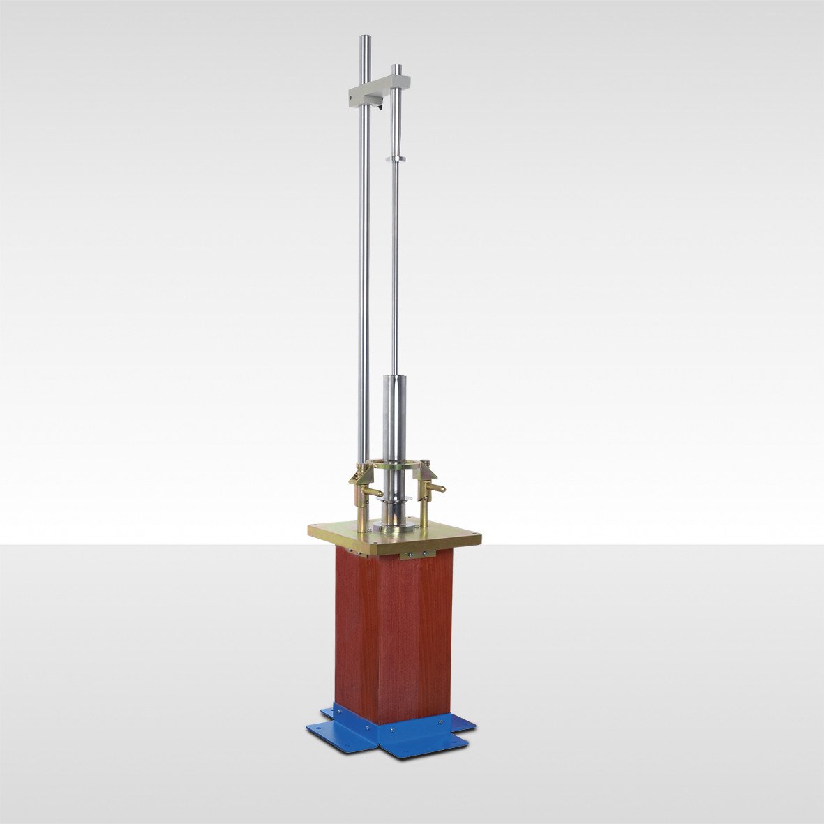
9. Marshall Manual Compaction Assembly, ASTM
Product Code
|
UTAS-0670 |
Manual Marshall Compaction Assembly, 4”, ASTM |
|
UTAS-0671 |
Marshall Compaction Hammer, 4” ASTM |
|
UTAS-0672 |
Wooden Compation Pedestal, ASTM, for UTAS-0670 |
|
UTAS-0674 |
Marshall Compaction Hammer BS |
|
UTAS-0676 |
Manual Marshall Compaction Assembly, 6”, ASTM |
|
UTAS-0677 |
Marshall Compaction Hammer, 6”ASTM, for UTAS-0676 |
|
UTAS-0678 |
Wooden Compaction Pedestal, 6”, ASTM, for UTAS-0676 |
|
UTAS-0667 |
Marshall Steel Block, Ø102 mm dia. and 50 mm height, |
|
UTAS-0668 |
Marshall Steel Block, Ø154mm dia. and 50 mm height, |
Standards
ASTM D6926, D5581; AASTHO T245 (only for UTAS-0071); BS-598
The UTAS-0670 and UTAS-0676 Marshall Manual Assemblies are used to prepare Marshall specimens manually.
The Compaction Assemblies consist of a Marshall Compaction Hammer and a Wooden Compaction Pedestal. The Pedestals are supplied complete with a steel plate, a mould holder and a hammer guide.
UTAS-0667 and UTAS-0668 Marshall Steel Blocks are used for initial heating of the foot of compaction hammer should be ordered separately.
|
|
Dimensions |
Weight (approx.) |
|
UTAS-0670 |
380x380x1570 mm |
45 kg |
|
UTAS-0671 |
100x100x108 mm |
8 kg |
|
UTAS-0672 |
350 x400x1600 mm |
42 kg |
|
UTAS-0674 |
150x150x150 mm |
8 kg |
|
UTAS-0676 |
400x380x1510 mm |
60 kg |
|
UTAS-0677 |
400x380x1510 mm |
60 kg |
|
UTAS-0667 |
150x150x100 mm |
4 kg |
|
UTAS-0668 |
200x200x100 mm |
8 kg |
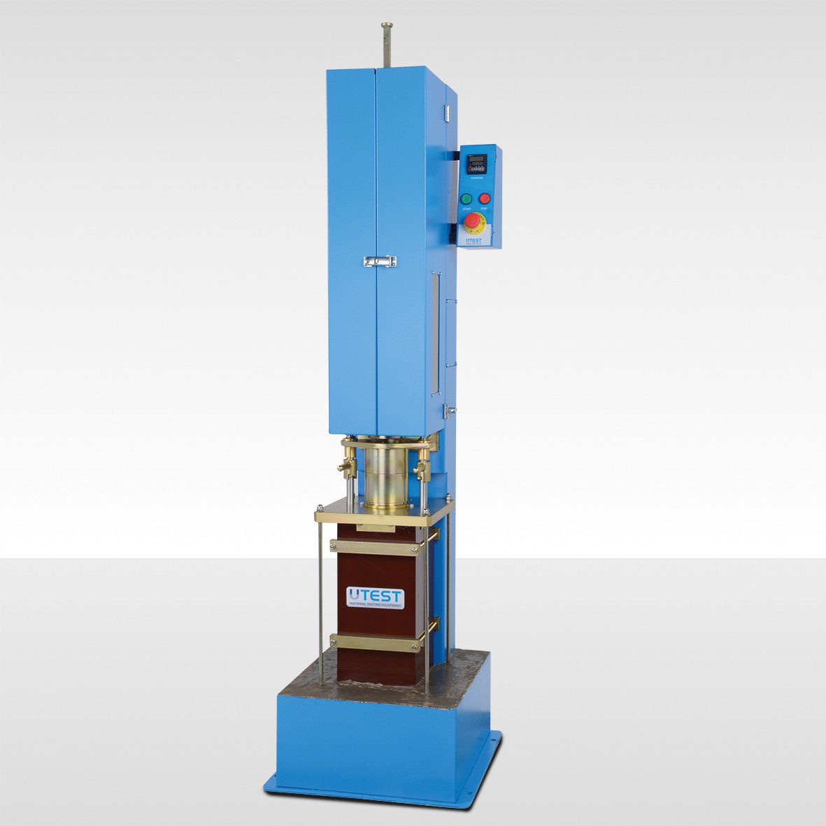
10. Automatic Marshall Impact Compactor, EN
Product Code
|
UTAS-0682E |
Automatic Marshall Impact Compactor with Wooden Pedestal, EN |
|
UTAS-0683E |
Automatic Marshall Impact Compactor with Wooden Pedestal and Soundproof Safety Cabinet |
|
UTAS-0667 |
Marshall Steel Block, Ø102 and 50 mm height |
|
UTAS-0641E |
Marshall Compaction Mould for Impact Compactor with Wooden Pedestal, EN, 101.6 mm |
|
Models for 220-240V 50 Hz, 1 ph. |
UTC-0682E-T |
UTC-0683E-T |
|
Models for 110-120V 60 Hz, 1 ph. |
UTC-0682E-N |
UTC-0683E-N |
|
Models for 220-240V 60 Hz, 1 ph. |
UTC-0682E-K |
UTC-0683E-K |
Standards
EN 12697-30, 12697-10, 12697-12
The UTAS-0682E and 0683E Automatic Marshall Compactor with wooden pedestal provides a uniform and even degree of compaction. The unit incorporates a compaction pedestal, comprising a laminated hardwood block secured to a concrete block by a 300 mm square x 25 mm thick steel plate.
The conveniently positioned control panel comprises of start/stop button, emergency stop button and a direct reading counter used to set the required number of blows.The apparatus stops automatically after the preset number of blows.
The compactors are equipped with a hand operated mould fixing mechanism which locks the mould in place during compaction and reduces vibration of the mould.
The standard model can be supplied with a safety/noise reduction cabinet. The cabinet is lined internally with soundproofing material to reduce sound level conforming to CE directives.
Particular attention has been paid to operator safety by the inclusion of various in-built safety features.
UTAS-0667 Marshall Steel Block which can be used for Initial heating of the foot of compaction hammer and Marshall moulds should be ordered separately.

Technical Specifications
|
Blows Frequency |
50 blows in 55 s to 60 s |
|
Free fall height of the sliding mass |
457±3 mm |
|
Total weight (Guide rod + Foot assembly+ Sliding mass) |
7850 ± 50 g |
|
Concrete Base Dimension |
450x450x200 mm |
|
Laminated Hardwork Block Dimensions |
200x200x450 mm |
|
Laminated Hardwork Block Density |
0,67 Mg/m3 to 0,78 Mg/m3 |
|
Product Code |
UTAS-0682E |
UTAS-0683E |
|
Dimensions |
520x520x1760 mm |
770x870x1970 mm |
|
Weight (approx.) 225 kg |
235 kg |
362 kg |
|
Power |
370 W |
370 W |
11. Automatic Marshall Impact Compactor for 4” Speciments, ASTM
Product Code
|
UTAS-0782A |
Automatic Marshall Compactor with Stationary Base for 4” dia. Specimens, ASTM |
|
UTAS-0783A |
Automatic Marshall Compactor with Stationary Base for 4” dia. Specimens with Soundproof Safety Cabinet, ASTM |
|
UTAS-0667 |
Marshall Steel Block, Ø102 and 50 mm height |
|
UTAS-0641A |
Marshall Compaction Mould ASTM 4” |
|
Models for 220-240V 50 Hz, 1 ph. |
UTC-0782A-T |
UTC-0783A-T |
|
Models for 110-120V 60 Hz, 1 ph. |
UTC-0782S-N |
UTC-0783A-N |
|
Models for 220-240V 60 Hz, 1 ph. |
UTC-0782A-K |
UTC-0783A-K |
Standards
ASTM D 1559 , ASTM D 6926-16; AASHTO T245
Automatic Marshall Compactor is designed to provide a stable and rigid mechanism to be used for preparation of bituminous specimens for Marshall Stability tests.
UTAS-0782A Compactor for compaction of 4” dia. specimens features a heavy-duty design, which stands up well to the constant jarring caused by the compaction process. The compactors are equipped with a hand operated mould fixing mechanism which locks the mould in place during compaction and reduces vibration of the mould
The conveniently positioned control panel comprises of start/stop button, emergency stop button and a direct reading counter used to set the required number of blows. The operator can keep track of the number of blows on an LCD display.
The apparatus stops automatically after the preset number of blows.
The standard models can be supplied with a safety/noise reduction cabinet. The cabinet is lined internally with soundproofing material to reduce sound level conforming to CE directives
UTAS-0667 Marshall Steel Blocks which can be used for initial heating of the foot of compaction hammer and Marshall moulds should be ordered separately.
Technical Specifications
|
Drop Numbers |
55 ± 5 blow/min |
|
Sliding Weight |
4536 ± 9 gr |
|
Falling Height |
457,2±1,5 mm |
|
Tamping Face Dia. |
98,5 mm |
|
|
UTAS-0782A |
UTAS-0783A |
|
Dimension |
400x440x1550 mm |
550x550x1650 mm |
|
Weight (approx.) |
110 kg |
250 kg |
12. Automatic Marshall Impact Compactor with Stationary Base for 4” and 6” Speciments, ASTM
Product Code
|
UTAS-0786A |
Automatic Marshall Compactor with Stationary Base for 4” and 6” dia Specimens, ASTM |
|
UTAS-0787A |
Automatic Marshall Compactor with Stationary Base for 4” and 6” dia. Specimens with Soundproof Safety Cabinet, ASTM |
|
UTAS-0668 |
Marshall Steel Block, Ø154 and 50 mm height |
|
UTAS-0789A |
Ø6” Hammer for UTAS-0786A and UTAS-0787A |
|
UTAS-0641A |
Marshall Compaction Mould ASTM 4” |
|
UTAS-0646A |
Marshall Compaction Mould ASTM 6” |
|
Models for 220-240V 50 Hz, 1 ph. |
UTC-0786A-T |
UTC-0787A-T |
|
Models for 110-120V 60 Hz, 1 ph. |
UTC-0786A-N |
UTC-0787A-N |
|
Models for 220-240V 60 Hz, 1 ph. |
UTC-0786A-K |
UTC-0787A-K |
Standards
ASTM D 1559 , ASTM D 6926-16, D5581; AASHTO T245
UTAS-0786A and UTAS-0787A Automatic Marshall Compactors are designed for the preparation of 4” and 6” bituminous specimens with the same device for Marshall Stability tests
The compactors have a heavy-duty design that withstands the continuous shaking caused by the compaction process and they are equipped with a hand operated mould fixing mechanism which locks the mould in place during compaction and reduces vibration of the moulds.
UTAS-0786A and UTAS-0787A Automatic Marshall Compactors are supplied complete 4” hammer. These compactors can easily be altered later to accommodate the 6” size by purchasing 6” hammer and molds. 6” hammer and the moulds (4” or/and 6”) should be ordered seperately.
The number of blows entered in the control panel by the user is applied automatically. By selecting the 55 blow, these compactors apply a speed of 55±5 compaction blows per minute to a 4” and 6” specimens.
The conveniently positioned control panel comprises of start/stop button, emergency stop button and a direct reading counter used to set the required number of blows. The operator can keep track of the number of blows on an LCD display.
The apparatus stops automatically after the preset number of blows.
The standard models can be supplied with a safety/noise reduction cabinet. The cabinet is lined internally with soundproofing material to reduce sound level conforming to CE directivesç
UTAS-0668 Marshall Steel Blocks which can be used for initial heating of the foot of compaction hammer and Marshall moulds should be ordered separately.
Technical Specifications
|
Mould Dia. |
Sliding Weight |
Falling Height |
|
4" |
4536 ± 9 gr 10 ± 0.02-lb |
457,2 ± 1,5 mm 18 ± 0.06 in |
|
6" |
10210 ± 10 gr 22.50 ± 0.02 lb |
457,2 ± 2,5 mm 18.0 ± 0.1 in |
|
Product Code |
UTAS-0786A |
UTAS-0787A |
|
Dimension |
377x485x1920 mm (14,84”x19,1”x75,6”) |
750x750x1975 mm (29,53”x29,53”x77,76”) |
|
Weight (approx.) |
180 kg (397 lb) |
320 kg (706 lb) |
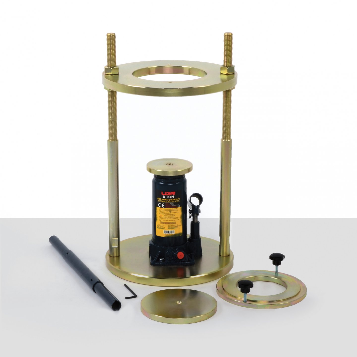
13. Marshall / CBR / Proctor Specimen Extruder
Product Code
|
UTGE-0080 |
Marshall-CBR-Proctor Specimen Extruder, 30 kN Capacity |
Standards
EN 12697-30, 13286-2, 13286-47; AASTHO T245, T134, T180,T193;
ASTM D1559, D698, D1557, D1883; BS 598-107, 1377-4, 1924-2
The specimen extruder is designed to easily extrude specimens from Marshall, CBR, standard and modified Proctor Moulds. The capacity of the extruder is 30 kN. Supplied complete with a manual hydraulic jack and 2 pcs. adaptor to extrude specimens from 100mm (4“), 150 mm (6”) inner diameter marshall, CBR, standard and modified proctor moulds.
|
Ram Travel |
130 mm |
|
Screw Travel |
90 mm |
|
Dimensions |
280x280x510 mm |
|
Weight (approx.) |
28 kg |
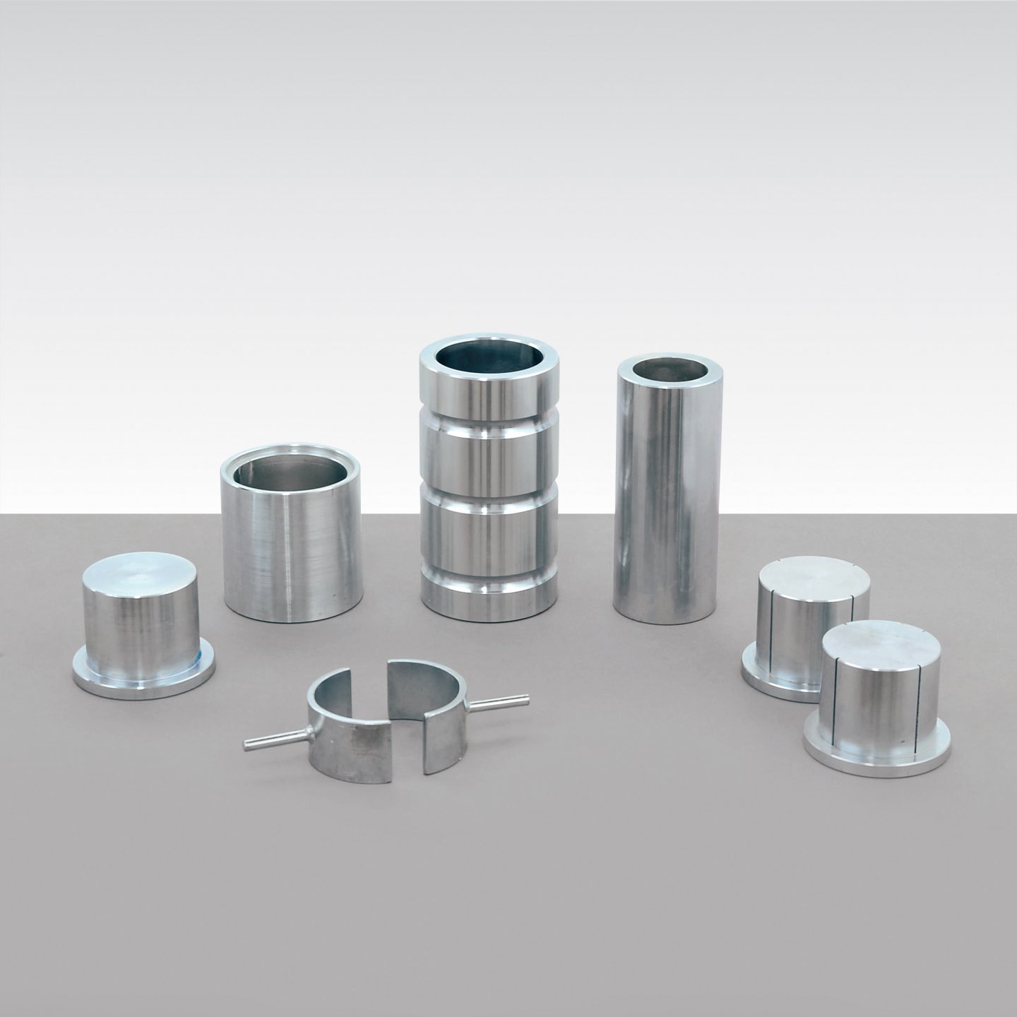
14. Duriez Compression Test Sets
Product Code
|
UTAS-0490 |
Duriez Compression Test Set, 80 mm dia. |
|
UTAS-0495 |
Duriez Grooved Piston Set, for UTAS-0490 |
|
UTAS-0496 |
Duriez Non-Grooved Piston Set, for UTAS-0490 |
|
UTAS-0503 |
Duriez Compression Test Set, 120 mm dia. |
|
UTAS-0505 |
Duriez Grooved Piston Set, for UTAS-0503 |
|
UTAS-0506 |
Duriez Non-Grooved Piston Set, for UTAS-0503 |
Standards
NF P98-251-1 and 4; EN 12697-12 Method B
The test sets are used to determine the physical and mechanical properties of bituminous mixtures, especially for the water sensitivity of bituminous specimens. One set for preparing 80 mm. specimens, the second set for preparing 120mm. specimens according to the maximum aggregate upper sieve size. All parts are made from steel protected against corrosion.
The compression test has to be performed with an electromechanical universal test machine such as UTM-8300.SMD2 model machine (300 kN Electromechanical Universal Test Machine. UTM-8300 can also be used for compaction transaction acc. to EN 12697-12 (Method B) for preparation of test specimens.
Grooved or Non-Grooved piston set includes upper and lower pistons.
Grooved piston set for cold mixes and Non-Grooved piston set for hot mixes should be ordered seperately.
Duriez compression test sets are supplied complete with;
- Mould
- Container
- Extraction Piston
- 2 pcs Half Spacers
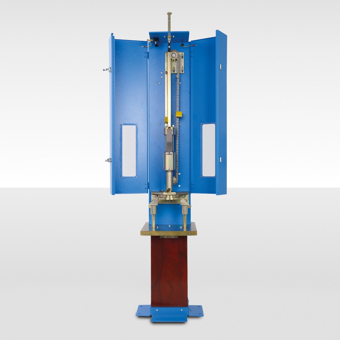
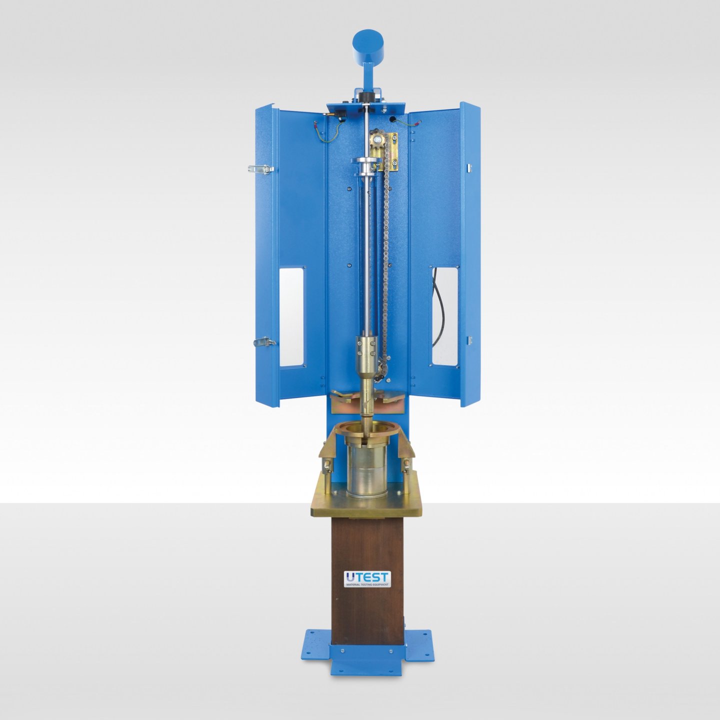
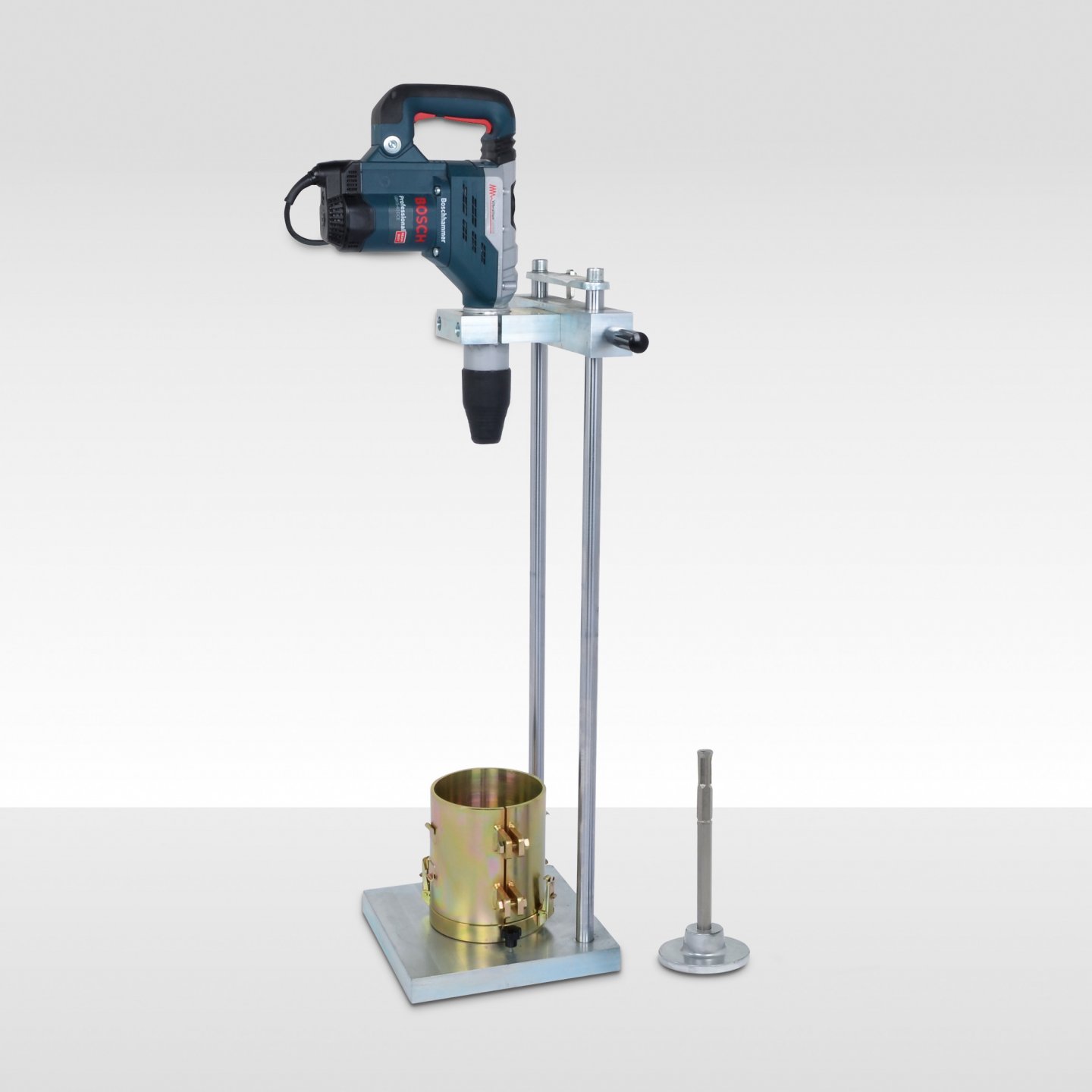
15. Vibratory Hammer for Compaction of Bituminous Mixtures and Soil
Product Code
|
UTS-0681-T |
Vibratory Hammer for Compaction of Bituminous Mixtures and Soil, 220-240V, 50 Hz, 1ph. |
|
UTS-0682 |
Steel Tamper, Ø146 mm |
|
UTAS-0885 |
P.R.D. Split Mould and Base Plate |
Standards
EN 12697-32, 12697-9, 12697-10, 13286-4; BS 1377-4
The UTS-0681 Vibratory compaction apparatus are used for preparing the test specimens of bituminous mixtures and soils.
P.R.D. (Percentage Refusal Density) Split Mould is split verticially on one side, attached to the base plate with clamp. Plated against corrosion.
UTAS-0885 The split mould and base plate should be ordered separately.
UTS-0682 the steel tamper which includes a tamping foot and a shank (UTS-0684) should be ordered separately when ordering the vibratory hammer.
|
Dimensions |
350x550x1300 mm |
|
Weight (approx.) (UTS-0681-T) |
105 kg |
|
Impact Rate |
1500-3000/min |
|
Power |
1150W |
16. Marshall Stability Test Machine with Proving Ring

Product Code
|
UTAS-1052 |
Marshall Stability Test Machine with Proving Ring, 50 kN |
|
UTAS-1057 |
Breaking Head (Stability Mould) for Ø4” specimen |
|
UTAS-1058 |
Breaking Head (Stability Mould) for Ø6” specimen |
|
UTAS-1063 |
Indirect Tensile (IDT) Strength/TSRTest Jig / Lottman Breaking Heads with Ø100mm Steel Loading Strips.EN, ASTM, AASHTO EN, ASTM, AASHTO |
|
UTAS-1064 |
Pair of Loading Strips for Ø150 mm Bituminous Specimens. EN, ASTM, AASHTO. For UTAS-1063E and UTAS-1066 |
|
UTAS-1065E |
Pair of Loading Strips for Ø160 mm Bituminous Specimens. EN. For UTAS-1063 |
|
UTAS-1066 |
Indirect Tensile (IDT) Strength / TSR Test jig / Lottman Breaking Heads with Ø4" loading strips. EN, ASTM, AASHTO. |
|
UTAS-1067A |
Pair of Loading strips for Ø6" bituminous specimens.ASTM, AASHTO. For UTAS- 1066 and UTAS-1063 |
|
UTAS-1086 |
Marshall Penetration Piston for StabilityTest, for UTAS-1052 |
|
Models for 220-240V 50-60 Hz, 1 ph. |
UTC-1052 |
|
Models for 110-120V 60 Hz, 1 ph. |
UTC-1052-N |
Standards
EN 12697-34, 12697-23, 12697-12 (Method A); ASTM D1559, D5581, D 6927, D 6931; AASHTO T245
The UTAS-1052 50 kN capacity Marshall Stability Test Machine with Proving Ring is used to determine the maximum load and flow values of bituminous mixtures.
The UTAS-1052 comprises a robust and compact two column frame with adjustable upper cross beam.
The unit is a bench mounted compression frame with motor and worm gear housed within the base unit.
The mechanical jack raises the lower platen at a constant speed of 50.8 mm/min as required in the relevant standard. For safety, the up and down travel of the lower platen movement is limited by limit switches.
Rapid adjustment of the platen is also provided using the control buttons on the front panel of the machine.
The measuring system consists of a 50 kN capacity load ring, digital flow meter (dial gauge) fitted to the breaking head. The UTAS-1052 Marshall Stability Machine is also suitable for testing 6” dia. specimens (152.4 mm) conforming to ASTM D5581.
The machine can be hand operated by a lateral hand wheel for calibration purposes; the hand wheel is supplied complete with the machine.
UTAS-1059 Holder for Digital Dial Gauge(UTGM-0148) is used for connecting to UTAS-1057, UTAS-1058 and UTAS-1063.
UTAS-1063 supplied with a pair of Ø100mm steel loading strip.Loading strips for Ø150 mm and/or Ø160mm and/or Ø4” and/or Ø6” specimens should be ordered separately.
UTAS-1066 supplied with a pair of Ø4” steel loading strip.Loading strips for Ø6” and/or Ø100mm and/or Ø150mm specimens should be ordered separately.
Breaking head/s and/or indirect tensile strength test jig/s should be ordered separately.
The UTAS-1052 Marshall Stability Test Machine is supplied complete with;
- Load Ring, 50 kN
- Penetration Piston for Marshall Stability Test (UTAS-1086)
- Digital Dial Gauge 25x0.01 mm (UTGM-0148) with Holder (UTAS-1059)
- Hand Wheel for Manual Control
|
Dimensions |
470x600x1180 mm |
|
Weight (approx.) |
102 kg |
|
Power |
1100 W |
17. Automatic Marshall Stability Test Machine

Product Code
|
UTAS-1056.ACPR |
Automatic Marshall Stability Test Machine with U-Touch PRO Control Unit, 50 kN / 11000 lbf capacity |
|
UTAS-1057 |
Breaking Head (Stability Mould) for Ø4” Specimen |
|
UTAS-1058 |
Breaking Head (Stability Mould) for Ø6” Specimen |
|
UTAS-1063 |
Indirect Tensile (IDT)Strenght /TSR Test Jig / Lottman Breaking Heads with Ø100mm loading strips.EN, ASTM, AASHTO |
|
UTAS-1064 |
Pair of Loading Strips for Ø150 mm Bituminous Specimens. EN, ASTM for UTAS-1063 and UTAS-1066 |
|
UTAS-1065E |
Pair of Loading Strips for Ø160 mm Bituminous Specimens. EN, for UTAS-1063 |
|
UTAS-1066 |
Indirect Tensile (IDT)Strenght /TSR Test Jig / Lottman Breaking Heads with Ø4” loading strips. EN, ASTM, AASHTO |
|
UTAS-1067A |
Pair of Loading Strips for Ø6” Bituminous Specimens. ASTM, AASHTO for UTAS-1063 and UTAS-1066 |
|
UTM-1088 |
Marshall Penetration Piston for Stability Test, for UTAS-1056 |
|
Models for 220-240V 50-60 Hz, 1 ph. |
UTC-1056.ACPR |
|
Models for 110-120V 60 Hz, 1 ph. |
UTC-1056.ACPR-N |
Standards
EN 12697-34, 12697-23, 12967-12 (Method A) ASTM D1559, D5581, D6927; D6931; AASHTO T245, T283, EN 12697-44; NF P98-251-2
The UTAS-1056.ACPR 50 kN capacity Automatic Marshall Stability Test Machine with U-Touch PRO Control Unit is designed to determine the maximum load and flow values of bituminous mixtures. With suitable accessories UTAS-1056.ACPR can also perform indirect tensile strength test of bituminous specimens.
The machine comprises of a robust, compact two column bench type compression frame with adjustable upper cross beam. Motor, worm gear system and U-Touch PRO Control Unit are housed within the base unit.For safety, up and down travel of the lower platen is limited by limit switches mounted on the gear system. Rapid adjustment of the platen can be done by using the up and down buttons located on the front panel. The machine can be hand operated by a lateral hand wheel for calibration purposes.
Breaking head/s, indirect tensile strength test jig/s and computer should be ordered separately.
UTAS-1063 supplied with a pair of Ø100mm steel loading strip.Loading strips for Ø150 mm and/or Ø160mm and/or Ø4” and/or Ø6” specimens should be ordered separately.
UTAS-1066 supplied with a pair of Ø4” steel loading strip.Loading strips for Ø6” and/or Ø100mm and/or Ø150mm specimens should be ordered separately.
The Automatic Marshall Stability Test Machine is supplied complete with;
- Load Cell, 50 kN
- Penetration Piston for Marshall Stability Test (UTM-1088)
- Linear Potentiometric Displacement Transducer 25 x 0.001 mm (UTGM-0062) with holder (UTAS-1060)
- Utest Software
- Ethernet cable for connecton PC
- Hand Wheel for Manual Control
MAIN FEATURES
- 50 kN capacity
- Stand alone fully automatic test execution
- For marshall, indirect tensile tests.
- Flow and stability values are automatically calculated and saved.
- Touchscreen graphic diplay 800x480 pixel, user-friendly menu consisting of icons, figures and diagrams.
- High resolution: 32 bits
- Large storing capacity on internal memory and data export function to usb stick drive
- Ethernet port for connection to PC
- Language and unit system selection
U-Touch PRO Control Unit
U-Touch PRO Control and Data Acquisition Unit is designed to control and process data from the loadcell and displacement transducers fitted on Marshall Stability test machine. UTAS-1056.ACPR can perform marshall, indirect tensile tests according to EN,ASTM/AASHTO standards listed above.
The Unit can perform tests stand-alone fully, automatic without the need of a PC or USOFT-1056 software. Software can be used to get additional advanges described in the section below.
U-Touch PRO incorporates a user-friendly interface that shows all existing menu options as buttons and tabs. Users can activate or deactivate certain functions easily and input test data by using touch keyboard. Parameters such as test information, user information, sample information and test parameters can be modified and saved for later use by operators.
Control Unit offers many additional unique features. Utouch Pro enables the users to display current memory usage and test results with its advanced data and memory management interface. U-Touch PRO can export, copy, or delete the test data saved in its internal memory. Results and additional information for previous tests can be recalled using U-Touch PRO. Test reports can be instantly printed using an (optional) thermal printer. U-Touch Pro TFT can simultaneously display machine status, test values, warnings during operation and test graphs in real time.
PLEASE see the pages of “General Properties of U-Touch PRO Control Units” for details of the properties of software and hardware of the Unit.

USOFT-1056 UTEST Software for UTAS-1056.ACPR
USOFT-1056 Marshall Stability Test Software is developed for Marshall stability tests in accordance with EN 12697-34, ASTM D 1559, D5581, D 6927, AASHTO T 245, NF P98-0251-2 indirect tensile tests in accordance with EN 12697-23 EN 12697-12(method A), ASTM 6931, AASHTO T283.
The software includes control of machine, acquisition of load and displacement data, saving them and generating reports. The software accepts specimen diameter and height as an input parameter. It automatically calculates correction factor coming from the standards with respect to specimen thickness. The stability value is calculated regarding this factor.
The software continuously updates load and displacement until the end of test. When the test is completed, the sharpest slope of the graph is calculated. The sharpest slope is shifted 1.5 mm to the right side of the graph and the intersection between 2nd slope and original test data is recorded as the stability value for the test. The horizontal distance between the intersection of first slope and X axis and intersection of test data with 2nd slope is recorded as “flow” value.
The point that this line crosses displacement axis is commented as an offset. This offset is subtracted from the displacement value at peak point and called as flow.
The report includes all results for 9 samples. The user can see 9 of the results on the same screen for easy comparision. The software supports SI, Imperial and kgf unit system.
See the pages of “General Properties of Utest USOFT Softwares” for detailed properties of the software.

|
Capacity |
50 kN |
|
Dimensions |
470x600x1180 mm |
|
Weight (approx.) |
102 kg |
|
Power |
1100 W |
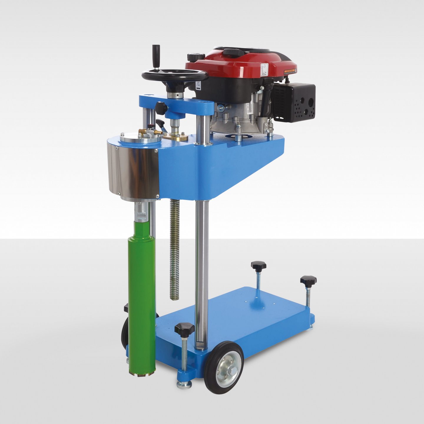
18. Core Drilling Machine
UTAS-2101_Core_Drilling_Machine+2.pdf
Product Code
|
UTAS–2101 |
Core Drilling Machine |
|
UTGD–0330 |
Coring Bit for Asphalt 50 mm dia. x 400 mm length |
|
UTGD–0330-S |
Coring Bit for Asphalt 50 mm dia. x 320 mm length |
|
UTGD–0332 |
Coring Bit for Asphalt 75 mm dia. x 400 mm length |
|
UTGD–0332-S |
Coring Bit for Asphalt 75 mm dia. x 320 mm length |
|
UTGD–0334 |
Coring Bit for Asphalt 100 mm dia. x 400 mm length |
|
UTGD–0334-S |
Coring Bit for Asphalt 100 mm dia. x 320 mm length |
|
UTGD–0336 |
Coring Bit for Asphalt 150 mm dia. x 400 mm length |
|
UTGD–0336-S |
Coring Bit for Asphalt 150 mm dia. x 320 mm length |
Standards
EN 12697-27, ASTM D 5361
Machine is designed to cut cores up to 150 mm diameter from concrete, asphalt and similar hard construction materials.
The machine comprises a vertical support column which carries the drill head/motor assembly. The motor assembly comprises a 6.5 Hp petrol engine.
A ball screw mechanism enables close control of the drilling pressure and rapid return when drilling is completed.
A water spraying assembly is mounted on the machine.
The complete assembly is supplied on a rigid wheel mounted metal base frame with leveling and fixing facility during the operation.
Coring Bits should be ordered separately.

UTGD–0336 UTGD–0334 UTGD–0332 UTGD–0330
|
Dimensions |
500x670x1050 mm |
|
Weight (approx.) |
90 kg |
|
Power |
6.5 Hp |
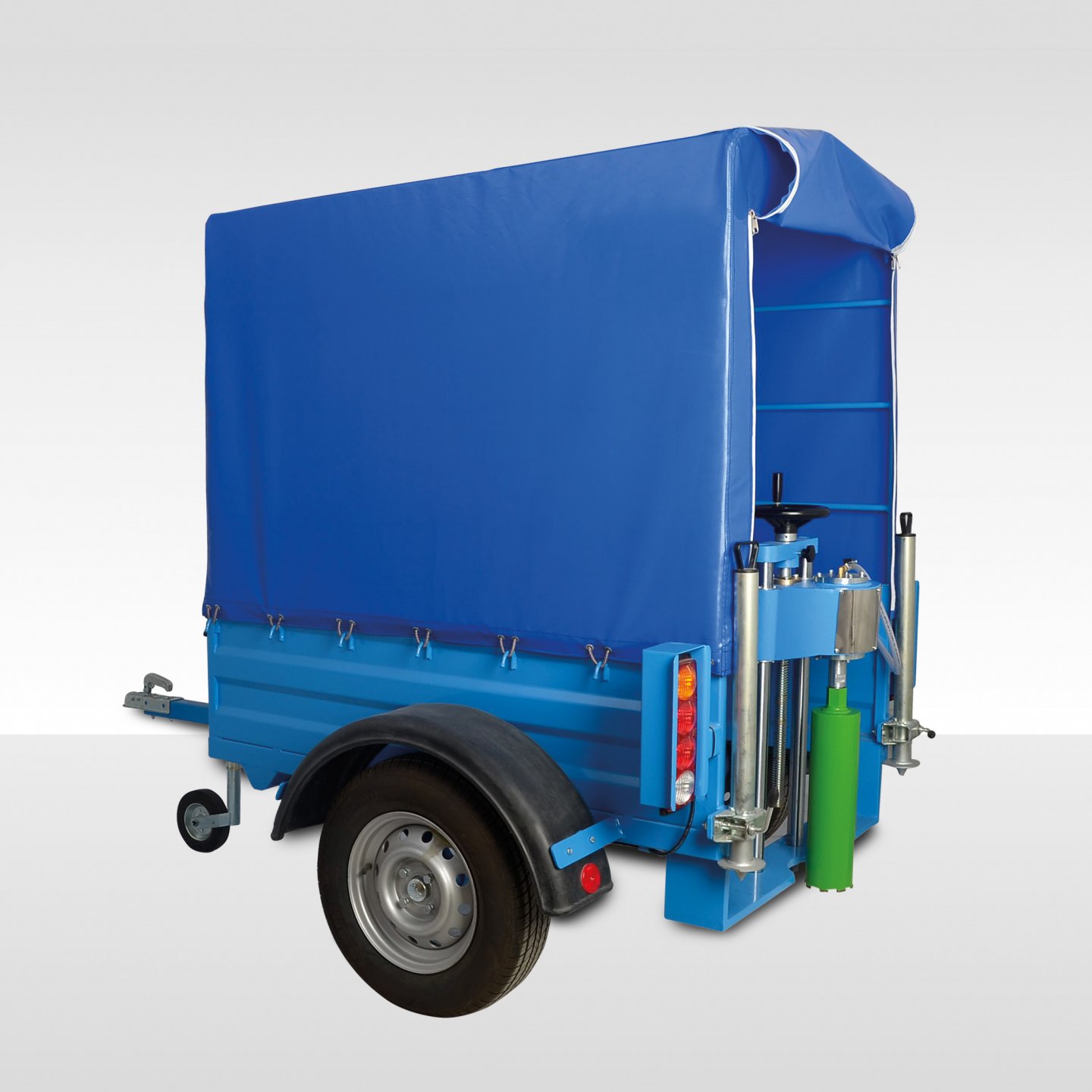
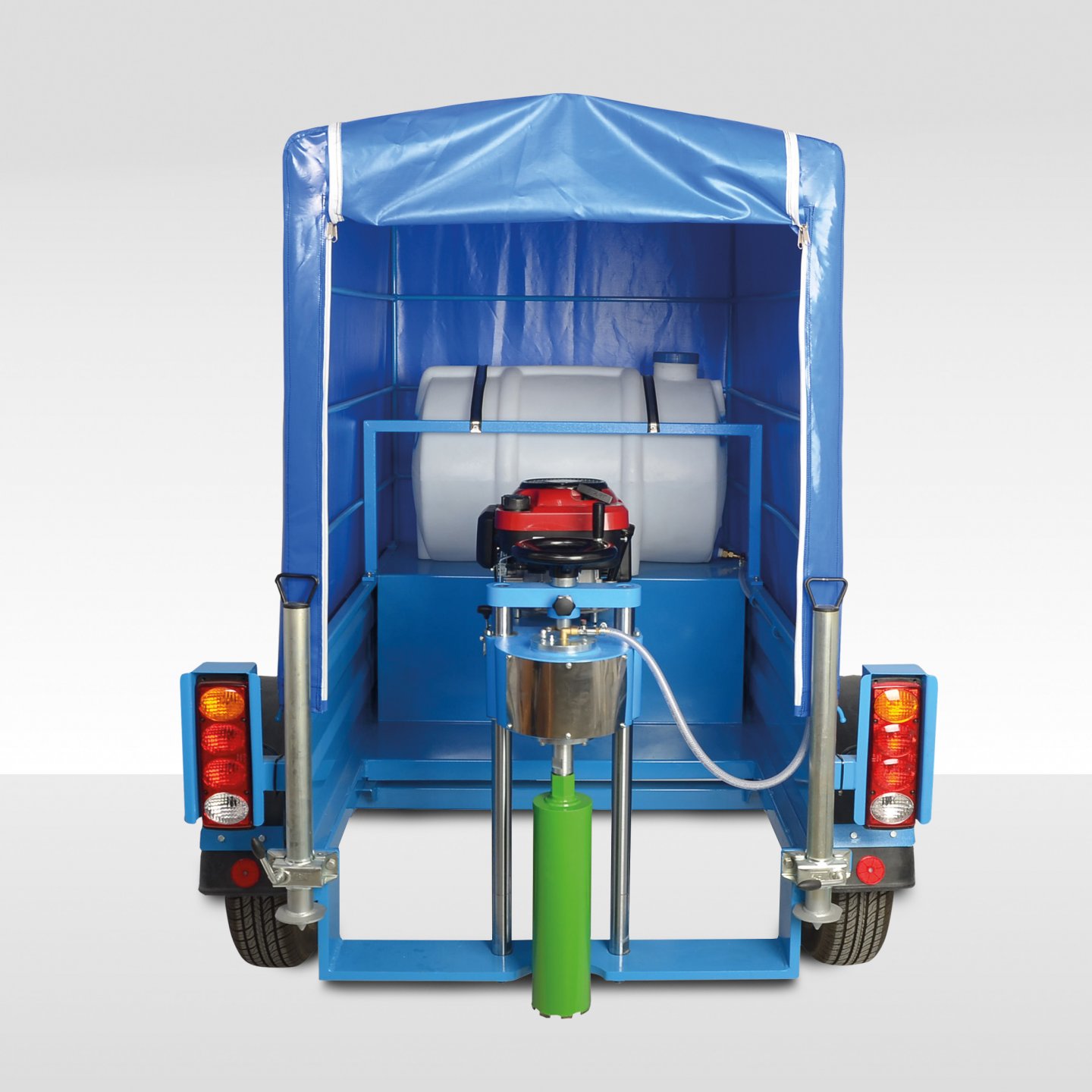
19. Core Drilling Machine on Trailer
Product Code
|
UTAS–2105 |
Core Drilling Machine on Trailer |
|
UTGD–0330 |
Coring Bit for Asphalt 50 mm dia. x 400 mm length |
|
UTGD–0330-S |
Coring Bit for Asphalt 50 mm dia. x 320 mm length |
|
UTGD–0332 |
Coring Bit for Asphalt 75 mm dia. x 400 mm length |
|
UTGD–0332-S |
Coring Bit for Asphalt 75 mm dia. x 320 mm length |
|
UTGD–0334 |
Coring Bit for Asphalt 100 mm dia. x 400 mm length |
|
UTGD–0334-S |
Coring Bit for Asphalt 100 mm dia. x 320 mm length |
|
UTGD–0336 |
Coring Bit for Asphalt 150 mm dia. x 400 mm length |
|
UTGD–0336-S |
Coring Bit for Asphalt 150 mm dia. x 320 mm length |
Standards
EN 12697-27, ASTM D 5361
Portable UTAS-2105Core Drilling Machine is designed to cut cores up to 150 mm diameter from concrete, asphalt and similar hard construction materials.
The machine comprises a vertical support column which carries the drill head/ motor assembly. The motor assembly comprises a 6.5 hp petrol engine.
A ball screw mechanism enables close control of the drilling pressure and rapid return when drilling is completed. A water spraying assembly is mounted on the machine.
The drilling machine is installed in a trailer for fast and precise sampling on-site. 100 litre water tank provides continuous lubrication during drilling to save time.
The two-wheeler taut liner trailer is fully equipped with brake lamps/hazard lashers/retro reflectors conforming to road traffic regulations.
The trailer is designed with a space to be used for storing the core samples. The two fixing legs are robustly designed for improved stabilization.
Coring Bits should be ordered separately.
UTGD–0336 UTGD–0334 UTGD–0332 UTGD–0330
|
Dimensions |
1520x2050x2050 mm |
|
Weight (approx.) |
300 kg |
|
Power |
6.5 Hp |
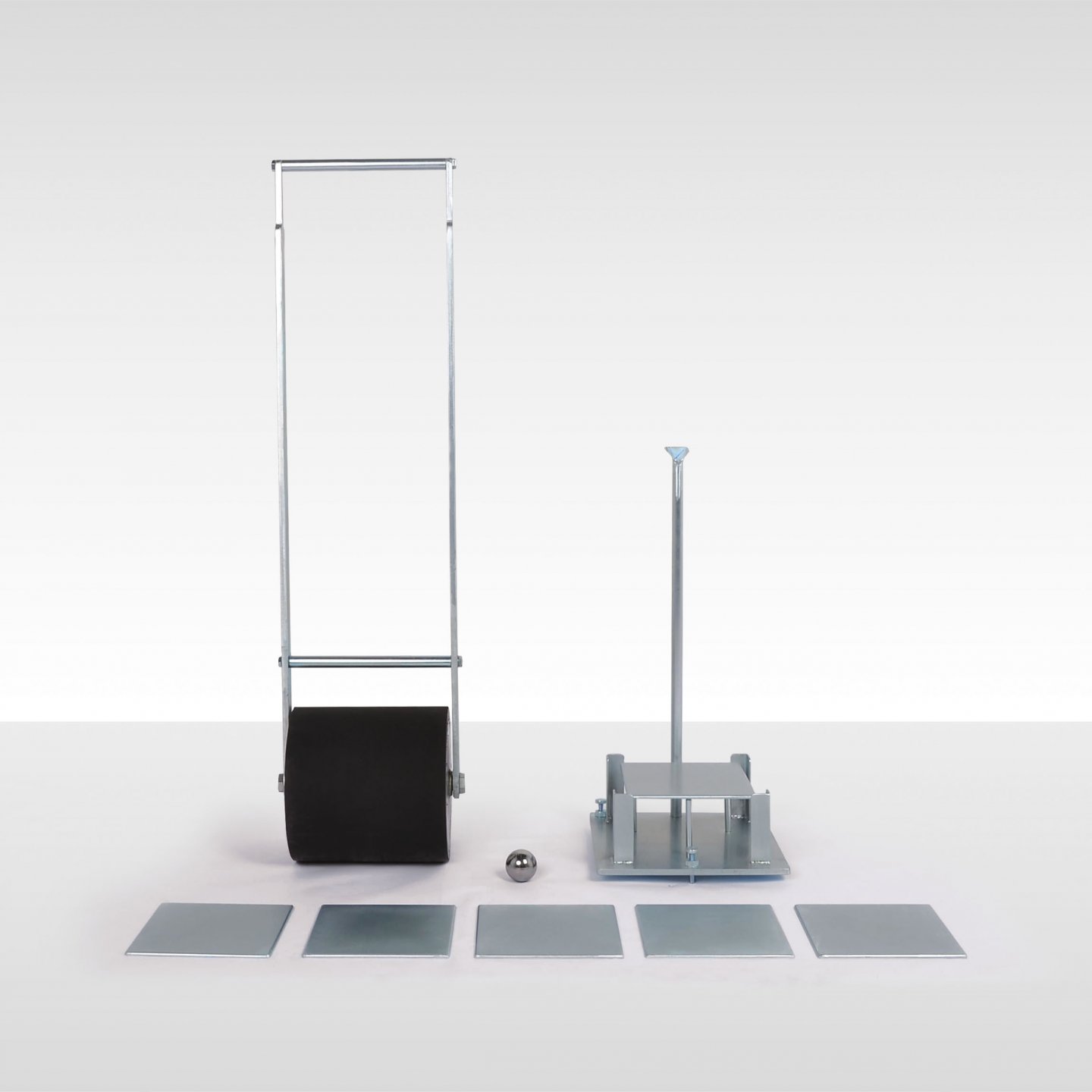
20. Vialit Plate (Adhesion Test) Apparatus
Product Code
|
UTAS-2112 |
Vialit Plate (Adhesion Test) Apparatus |
|
UTAS-2113 |
Steel Ball, 512gr, for UTAS-0112 |
|
UTAS-2114 |
Mechanical Aggregate Deployment for UTAS-0112, 100 chippings |
Standards
EN 12272-3; NF P98-274-1
The UTAS-0212 Vialit Plate Apparatus is used to assess the adhesion property of aggregates to bitumen.
Supplied complete with a metal basement with three vertical pointed rods to hold the flat steel plate, 50 cm. high vertical rod with a slot at the upper end for the steel ball to drop, a 512 g steel ball, 6 metal test plates and a hand operated rubber wheel roller. The mechanical aggregate deployment should be ordered seperately.
The test plate, coated by bitumen on one face and spread with the aggregate chippings in a standard way is rolled using the roller and then placed on the three-point support base.
The steel ball drops three times from the slot, and the chippings that become loose after the three impacts are counted and checked.

UTAS-2114
The Vialit Plate (Adhesion Test) Apparatus is supplied complete with;
- Flat Steel Plates, 6 pcs.
- Steel Ball, 512 g
- Rubber Wheel Roller, hand operated
|
Dimensions |
550x1650x650 mm |
|
Weight (approx.) |
40 kg |
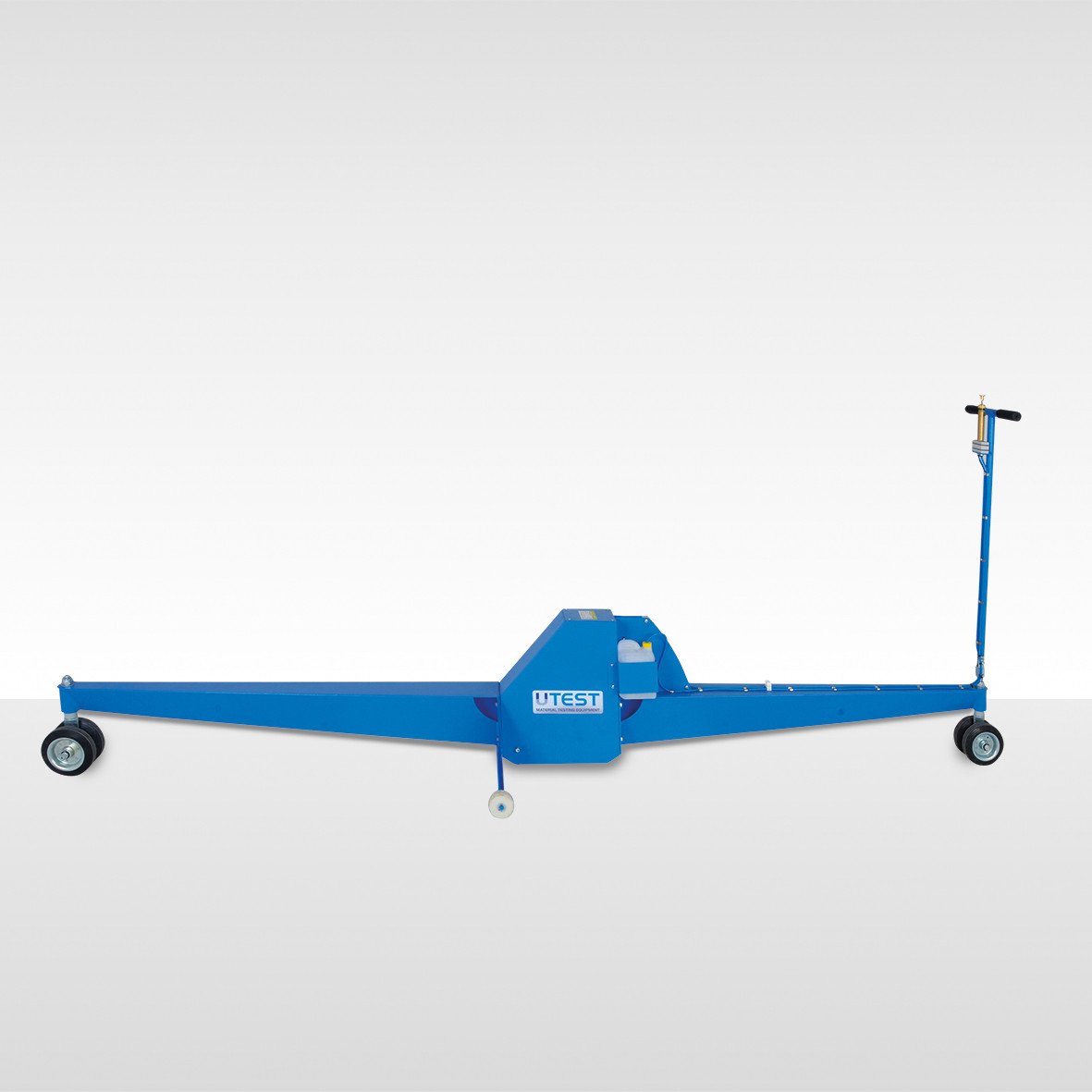
21. Travelling Beam Device
Product Code
|
UTAS–2125 |
Travelling Beam Device |
The UTAS-2125 Travelling Beam Device is used to check for any irregularities in both concrete and bituminous road surfaces.
Deviation of the surface from a straight-line is shown on a scale calibrated in increments of 2 mm in the 0-10 mm range and 5 mm increments in the 10-25 mm range. It comprises a manual dye marker which is used to mark irregular surface sections when found.

|
Dimensions |
720x2900x500 mm (packed) |
|
Weight (approx.) |
45 kg |
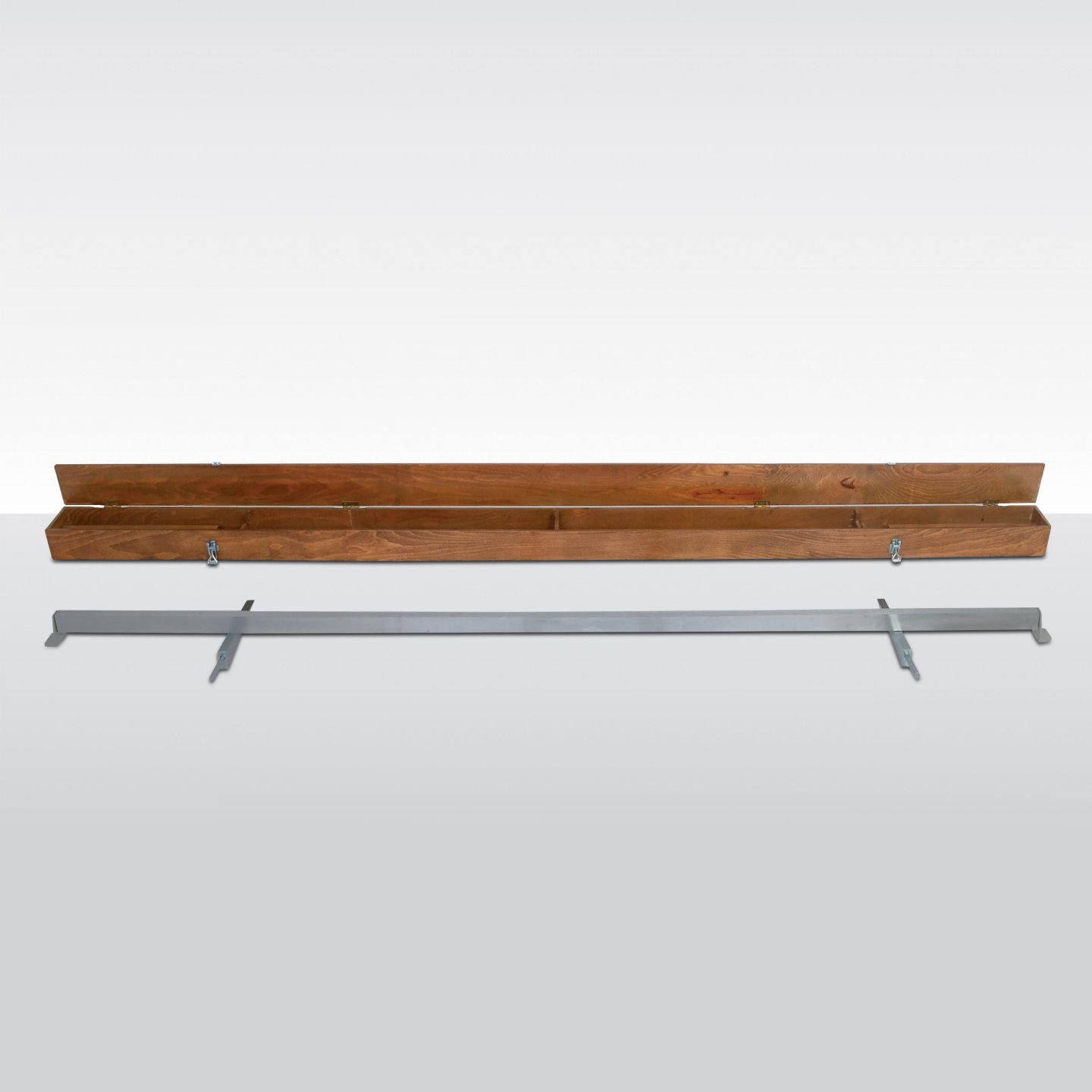
22. MOT Straightedge
Product Code
|
UTAS-2127 |
MOT Straightedge, EN |
|
UTAS-2128 |
Wooden Carrying Case, for UTAS-2127 |
Standards
EN 13036-7
The straightedge is used for measuring single irregularities attributable to quality defects in new surface course(s) of roads, airfields and other trafficked surfaces as well as in-service surfaces.
UTAS-2127 is supplied with two steel wedges.
Wooden carrying case should be ordered separately.
|
Dimensions |
200x3100x150 mm (for case) |
|
Weight (approx.) |
40 kg (with case) |
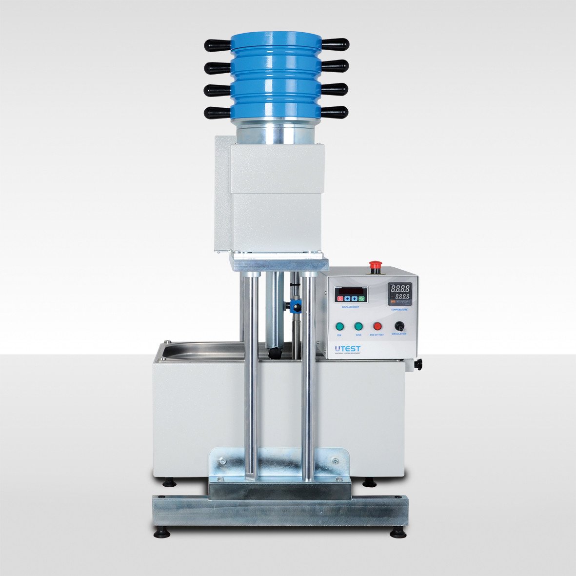
23. Automatic Asphalt Indentation Penetrometer
Product Code
|
UTAS-2130 |
Automatic Asphalt Indentation Penetrometer, EN |
|
UTAS-2134 |
Spare Indentor Pins (100mm2 and 500 mm2) for UTAS-2130 |
|
UTAS-2135 |
Adjustable mould for the test cube (69mm) for UTAS-2130 |
|
UTAS-2136 |
Metal Intermediate Plate for UTAS-2130 |
|
UTAS-2137 |
Calibration Block for UTAS-2130 |
|
UTAS-2138 |
The appartus for preparing the test cubes for UTAS-2130 |
|
UTCM-0926 |
Cube Mould 70.7 mm, BS, steel, for UTCM-0930 and UTAS-2130 |
|
Models for 220-240V 50-60 Hz, 1 ph. |
UTC-2130 |
|
Models for 110-120V 60 Hz, 1 ph. |
UTC-2130-N |
Standards
TS EN 12697-20
UTAS-2130 Automatic Indentation Penetrometer determines the resistance of an asphalt cube and cylindrical specimens to indentation when force is applied to them using a cylindirical pin in a defined period. Maximum nominal size of the aggregates should be less or equal to 16 mm.
UTAS-2130 can apply a 25 N prelaminary force and than 525 N total force without touching the test weights with electromechanical method acc. to TS EN 12697-20.
UTAS-2130 consists of a four-columns frame combined with an assebly for force application and a stainless steel 25L water bath with drain facility, a digital control unit with immersion type heater-agitator, 50 x 0.01 mm displacement transducer with holder, calibration block, interchangeable indentor pin with 100 mm2 and 500 mm2, an adjustable mould 69mm, a metal intermediate plate and a free software.
Cube mould and the appartus for preparing the test cubes should be ordered seperately.
Key Features
- Stainless steel
- Temperature control
- Digital indicator
- Ethernet connection
Software
UTAS-2130 is supplied with software developed by Utest that allows automatic capture to PC of test data. Software is capable of showing the test data in real time, storing the results and real time temperature monitoring.
Technical Specification
|
Preliminary Force |
(25 ± 1) N |
|
Total Test Force |
(525 ± 1) N |
|
100 mm2 Diameter Indentor Pin |
(11.3 ± 0,1)mm |
|
500 mm2 Diameter Indentor Pin |
(25.2 ± 0,1) mm |
|
Deformation of Apparatus Upon Application and Removal of Forces |
<0.01 mm |
|
Water Tank Capacity |
25 litres |
|
Water Temperature Range |
Ambient to the test temperatures |
|
Water Temperature Stability |
Accuracy of ± 1 °C. |
|
Digital Indicator Resolution |
0.01 mm |
|
Dimensions |
590x1030x480 cm |
|
Weight (approx.) |
196 kg |
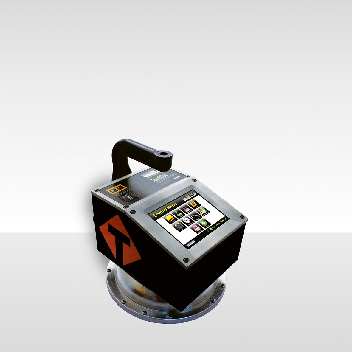
24. Non-Nuclear Asphalt Density Gauge
Product Code
|
UTAS–2160 |
Non-Nuclear Asphalt Density Gauge |
Standards
ASTM D7113; AASTHO T 243-12
Non-Nuclear Asphalt Density Gauge is used for determination of density of asphalt specimens with non nuclear method. UTAS-2160 is equipped with a touch screen and user friendly graphical menu interface, running Microsoft Windows silently in the backround for flawless operation, easy software are upgrades and enchanced user support.
The instrument general specifications are;
- Full colour graphics driven interface, 480 x 640 VGA touch screen display with LED backlight for easy visibility.
- Displays GPS status, available battery voltage, low battery and date/time,
- Rugged case design made from aluminum, powder-coated gloss black with orange reflective vinyl graphics increasing driver awareness to road workers at night
- Data Management Feature, quickly access, can be downloaded and deleted project data,
- Required files can be downloaded to UTS-1280 via. USB,
- Fast, reliable, accurate, and repeatable in real time, User Friendly and cost effective.
- The most impoftant point is; Non-Nucleer means no Badges or licences and no storage or transport concerns.
OPERATIONAL FEATURES
- Display: Full color graphics driven user interface, 480x640 VGA touch screen display with LED backlight for easy visibility in daylight or dark environments.
- Status Bar: Displays GPS status, Data Save status, battery voltage, low battery, date and time
- Project Details: Stores up to 20 projects with details,
- Mix Details: Stores up to 20 mixes, details include (MTD, Mix Name, Stone Size, Depth, Offset, Operator Name)
- Data Logging: When enabled, stores all measurements taken in single or average modes, (Status Bar Icon)
- Reports: Easily download data to be imported into Excel
- GPS Control: When activated will display latitude and longitude positions, number of satellites the gauge is connected to as well as the UTC date and time, also available in UTM format. GPS information will store with each measurement when Data Save and GPS feature is enabled, (Status Bar Icon)
- Update Software: One touch upload of new software usinga USB memory stick
- Data Management: Quickly access, download or delete your project data
- Set Time & Date: Quick time and date setup, MM/DD/YY and DD/MM/YY formats
- Units: Interchangeable settings for Density (kq/rn3, Ib/ft3), Temp (°C,°F), Depth (in, mm) and Stone Size (in, mm)
- Standardization: While gauge is still in the case, a quick one touch measurement will ensure the gauge is still in proper working mode
- Calculator: Built in four function calculator
- Enhanced Customer Support: Diagnostic screen to aid in factory support
- User Programmable Target Density: Used for calculating compaction %
- User Changeable Battery: Easily change batteries in the field
Operational Specification
Mode
|
Single |
Reading time less than five (5) seconds. Stores Data |
|
Average |
Averages five (5) readings and stores data including date and time. Stores thousands of records |
|
Continuous |
Instantaneous density readings. |
|
Segregation |
Identifies variations in material density associated with segregation. Function |
Function
|
Density |
% Compaction |
|
Integrated Temperature Sensing |
Real time temperature display O° F to 350 °F (-17.7° C to 177.6° C) |
Calibration Mode
|
Normal |
Correlation offset to cores |
Measurement Specification
|
Sensing Area |
11 in. (27.9cm) dia. base allows optimum measurement on fine and coarse material types. |
|
Measurement Depth |
User selected and adjustable from 1 in. to 4 in. (2Smm to 1OOmm) |
|
Measurement Display |
Density, % Compaction, Surface Temperature, Mix Name & Project Name |
Mechanical Specification
|
Unit Weight |
6.44kg (14.2 lbs) |
|
Unit Dimensions |
27,9 cm x 27,9 cm x 30,4 cm (11"x11"x12" High) with handle extension 73,6 cm High (29") |
|
Shipping Weight |
w/ Case 19,27 kg (42,5 lbs) |
|
Shipping Dimensions |
63,5 cm x 50,8 cm x 35,5 cm (25" x 20" x 14") |
Electrical Specification
|
Microprocessor |
Controlled |
|
CE Mark |
Complies with EN 61000-4-2, 61000-4-3, 61000-4-8 |
|
Battery |
14.0 Amp-hr NiMH, 7.2 V |
|
Recharge Time |
4 hours |
|
Battery Charger |
Self Contained CE & UL Certified Universal AC Charger, DC Charger |
|
Computer Ports |
1 USB Port |
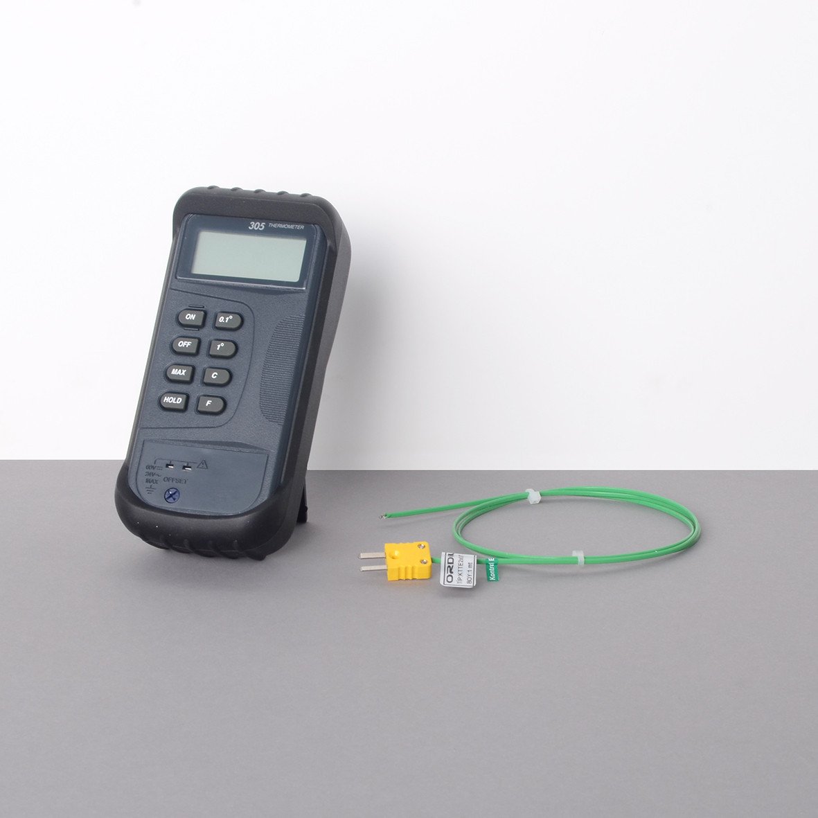
25. Hand Type Digital Thermometer
Product Code
|
UTGT-1350 |
Hand Type Digital Thermometer, -50° C to 1350° C |
|
UTGT-1370 |
200 mm Hand-Held Penetration Probe, for Tempereture Mesurement (Ø6mm), with 1.5m cable and connector, up to 1200° C, Type: OM07-K160-20 M 1K |
|
UTGT-1371 |
300 mm Hand-Held Penetration Probe, for Tempereture Mesurement (Ø6mm), with 1.5m cable and connector, up to 1200° C, Type: OM07-K160-30 M 1K |
|
UTGT-1372 |
500 mm Hand-Held Penetration Probe, for Tempereture Mesurement (Ø6mm), with 1.5m cable and connector, up to 1200° C, Type: OM07-K160-50 M 1K |
Digital thermometer and penetration probes are used together for measuring the delivery and compaction temperatures of bituminous mixtures. Preffered penetration probe should be ordered with UTGT- 1350.
|
Dimensions |
50x110x170 mm |
|
Weight (approx.) |
0,40 kg |
UTEST CONCRETE TESTING
1. ASTM & AASTHO - Automatic Compression Testing Machines for Cylinders
Product Code
|
UTC-4601.FPR |
600kN (135000 lbf) Automatic Compression Testing Machines with Ø105 mm Bearing Blocks for Cylinders, ASTM & AASHTO |
|
UTC-4701.FPR |
1100kN (245000lbf) Automatic Compression Testing Machines with Ø105 mm Bearing Blocks for Cylinders, ASTM & AASHTO |
|
UTC-4602.FPR |
600 kN (135000 lbf) Automatic Compression Testing Machines with Ø165 mm Bearing Blocks for Cylinders, ASTM & AASHTO |
|
UTC-4702.FPR |
1100kN (245000lbf) Automatic Compression Testing Machines with Ø165 mm Bearing Blocks for Cylinders, ASTM & AASHTO |
|
UTC-4712.FPR |
1500 kN(335000 lbf) Automatic Compressıon Testıng Machines with Ø165 mm Bearing Blocks for Cylinders, ASTM & AASHTO |
|
UTC-4722.FPR |
2000 kN (450000 lbf) Automatic Compressıon Testıng Machines with Ø165 mm Bearing Blocks for Cylinders, ASTM & AASHTO |
|
UTC-4732.FPR |
3000 kN (670000 lbf) Automatic Compressıon Testıng Machines with Ø165 mm Bearing Blocks for Cylinders, ASTM & AASHTO |
|
UTC-0210 |
High Precision Pressure Transducer and Electronic |
|
UTC-4680A |
Pedestal for ASTM 600 kN (135000 lbf), 1100 kN (245000 lbf) and 1500 kN (335000 lbf), Compression Testing Frames with Welded Walls |
|
UTC-4682A |
Pedestal for ASTM 1550 kN (348000 lbf), 2000 kN (450000 lbf), 2200 kN (495000lbf) and 3000 kN (670000 lbf) Compression Testing Frames with Welded Walls |
|
UTC-0220 |
Serial Printer, Thermal Type |
|
Models for 220-240V 50-60 Hz, 1ph. |
||||||
|
UTC-4601.FPR |
UTC-4701.FPR |
UTC-4602.FPR |
UTC-4702.FPR |
UTC-4712.FPR |
UTC-4722.FPR |
UTC-4732.FPR |
|
Models for 110-120V 60 Hz, 1ph. |
||||||
|
UTC-4601.FPR-N |
UTC-4701.FPR-N |
UTC-4602.FPR-N |
UTC-4702.FPR-N |
UTC-4712.FPR-N |
UTC-4722.FPR-N |
UTC-4732.FPR-N |
Standards
ASTM C39; AASHTO T22
UTC-4701.FPR, UTC-4701.FPR, UTC-4602.FPR, UTC-4702.FPR, UTC-4712, UTC-4722.FPR and UTC-4732.FPR models Automatic Compressıon Testıng Machines are manufactured for compression testing of acc. to ASTM & AASHTO standards. These machines also meet the requirements of CE norms with respect to the health and safety of the operator.
The machines allow inexperienced operators to perform the test. Once the machine has been switched on and the specimen is positioned and centered by the help of concentric centering line/s of lower bearing block (except Ø105 mm), the only required operations are;
- Setting test parameters, including pace rate (only required when the specimen type is changed).
- Pressing the START button on the control unit.
- The machine automatically starts the rapid approach, when the specimen touches the upper platen the rapid approach is ended and starts loading at the pace rate that selected by user and stops once the specimen fails.
- Automatically saves the test parameters and test results.
The Machines consist of a welded steel frame (see table) and UTC-4830FPR automatic hydraulic power pack with U-Touch PRO Control Unit.
UTC-4680A or UTC-4682A Pedestals that are made of steel to facilitate the user’s placement of specimens in the machines for compression test should be ordered separately.
Main Features
- Pace Rate control between 1 kN to 25 kN
- Accuracy Class A acc. to E74 and Class 1 acc. to ISO 7500-1 starting from with the 5% of the machine capacity (Special calibration option Class A starting from 1% of the full range with UTC-0210)
- Supplied with factory calibration certificate for load measurement
- Tests automatically with closed loop control
- The tests can be performed by controlling the machine either on U-Touch PRO control unit (UTC-4930.FPR) or on a computer with using free UTEST Software (USOFT-4830.FPR) which is provided free of charge with the machines.
- Load measurment with a pressure transducer
- Hydraulic pump with dual stage for rapid approach
- Welded steel walled frame with a single acting piston
- Piston return at the end of test automatically
U-Touch PRO Control Unit for Automatic Compression / Flexure Testing Machines
U-Touch PRO Control Unit UTC-4930.FPR is designed to perform automatically compression, flexure and splitting tensile strength tests of construction materials such as concrete, cement mortar, masonary units/blocks by controlling the Utest automatic compression / flexure testing machines.
All the operations of U-Touch PRO are controlled from the front panel touch screen display.
U-Touch PRO Control Unit has easy to use menu options. It displays all menu option listings simultaneously, allowing the operator to access the required option in a seemless manner to activate the option or enter a numeric value to set the test parameters. Digital graphic display is able to draw real-time "Load vs. Time", or "Stress vs. Time" graphics.
PLEASE see the pages of “U-Touch PRO Control Unit for Automatic Compression/Flexure Testing Machines” for details of the properties.
UTEST Software for Automatic Compression / Flexure Testing Machines
UTEST software USOFT-4830.FPR provides to perform automatically compression, flexure and splitting tensile strength tests of construction materials such as concrete, cement mortar, masonary units/blocks by controlling the Utest automatic compression / flexure testing machines
The advantages of performing tests on computer with using UTEST Software, such as reporting, graphical output, etc. can be seen in detail at the pages of UTEST Software for Automatic Compression / Flexure Testing Machines.
Optional Additional Frame
For compression and especially flexural testing, additionally second testing frame should be ordered separately.
In this case, the machines provide load control of two seperate testing frames with closed-loop P.I.D control with automatic test procedure by using selecting test channel and additional selector valve.
Safety Features
- Maximum pressure valves to avoid machine overloading
- Limit switch for piston stroke
- Emergency stop button
- Removable transparent front and rear safety doors
- Software controlled maximum load value
- The front safety doors have an automatic safety device to stop the machine if the door is opened during a test.
|
ASTM & AASHTO LOW CAPACITY AUTOMATIC COMPRESSION TESTING MACHINES FOR CYLINDERS |
||||
|
Models |
UTC-4601.FPR |
UTC-4701.FPR |
UTC-4602.FPR |
UTC-4702.FPR |
|
Product Photo |
|
|
|
|
|
Capacity |
600kN (135000 lbf) |
1100 kN (245000 lbf) |
600kN (135000 lbf) |
1100 kN (245000 lbf) |
|
Frame Type |
Welded Steel |
Welded Steel |
Welded Steel |
Welded Steel |
|
Lower Bearing Block, Dimensions (D) |
Ø105 mm (4,13”) |
Ø105 mm (4,13”) |
Ø 165 mm (6,50") |
Ø 165 mm (6,50") |
|
Upper Bearing Block, (With Spherically Seating Assembly) Dimensions (C) |
Ø 165 mm (6.5”) |
Ø 165 mm (6.5”) |
Ø 165 mm (6,50") |
Ø 165 mm (6,50") |
|
Surface Hardness of Bearing Blocks |
≥ 55 HRC |
≥ 55 HRC |
≥ 55 HRC |
≥ 55 HRC |
|
Flatness Tolerance |
0,02 mm / 150 mm (0,001”/6”) |
0,02 mm / 150 mm (0,001”/6”) |
0,02 mm / 15 0mm (0,001”/6”) |
0,02 mm / 150 mm (0,001”/6”) |
|
Piston Diameter |
150 mm (5,9”) |
190 mm (7,48”) |
150 mm (5,9”) |
190 mm (7,48”) |
|
Piston Stroke |
50 mm (1,97”) |
50 mm (1,97”) |
50 mm (1,97”) |
50 mm (1,97”) |
|
Maximum Vertical Clearance Between Bearing Blocks (E) |
340 mm (13,4”) |
380 mm (15”) |
340 mm (13,4”) |
380 mm (15”) |
|
Horizontal Clearance (B) |
230 mm (9,06”) |
270 mm (10,6”) |
230 mm (9,06”) |
270 mm (10,6”) |
|
For Cylinder Specimens Sizes |
Ø100x200 mm (4”x8”) |
Ø100x200 mm (4”x8”) |
Ø100x200 mm (4”x8”) (**) |
Ø100x200 mm (4”x8”) Ø160x320 mm |
|
Power |
550 W |
550 W |
550 W |
550 W |
|
Oil Capacity |
20 L (0,7 ft3) |
20 L (0,7 ft3) |
20 L (0,7 ft3) |
20 L (0,7 ft3) |
|
Maximum Working Pressure |
340 Bar |
390 Bar |
340 Bar |
390 Bar |
|
Dimensions (wxlxh) (Axd*xF) |
640x454x922mm (25,2”x17,87”x36,3”) |
680x454x1042mm (26,77”x17,87”x41,02”) |
640x454x922mm (25,2”x17,87”x36,30”) |
680x454x1042mm (26,77”x17,87”x41,02”) |
|
Weight |
365 kg (805 lbs) |
463 kg (1020 lbs) |
376 kg (830 lbs) |
474 kg (1045 lbs) |
|
Pedestal (Optional) |
UTC-4680 |
UTC-4680 |
UTC-4680 |
UTC-4680 |
|
(d*) depth (**) Limited by capacity of the frame The Machines are supplied complete with; • UTC-4601.FPR and UTC-4602.FPR : 100 mm (3,93”), 50 mm (1,97”), 30 mm (1,2”) height x Ø165 mm (Ø 6,5”) distance pieces • UTC-4701.FPR and UTC-4702.FPR: 100 mm (3,93”), 50 mm (1,97”), 2 pcs. 30 mm (1,2”) height x Ø165 mm (Ø 6,5”) distance pieces • Removable transparent front and rear safety doors • The front safety doors have an automatic safety device to stop the machine if the door is opened during a test |
||||
|
ASTM & AASHTO AUTOMATIC COMPRESSION TESTING MACHINES FOR CYLINDERS |
|||
|
Models |
UTC-4712.FPR |
UTC-4722.FPR |
UTC-4732.FPR |
|
Product Photo |
|
|
|
|
Capacity |
1500 kN (335000 lbf) |
2000 kN (450000 lbf) |
3000 kN (670000 lbf) |
|
Frame Type |
Welded Steel |
Welded Steel |
Welded Steel |
|
Lower Bearing Block, Dimensions (D) |
Ø 165 mm (6.5”) |
Ø 165 mm (6.5”) |
Ø 165 mm (6.5”) |
|
Upper Bearing Block, (With Spherically Seating Assembly ) Dimensions (C) |
Ø 165 mm (6.5”) |
Ø 165 mm (6.5”) |
Ø 165 mm (6.5”) |
|
Surface Hardness of Bearing Blocks |
≥ 55 HRC |
≥ 55 HRC |
≥ 55 HRC |
|
Flatness Tolerance |
0,02 mm/150 mm (0,001”/6”) |
0,02 mm/150 mm (0,001”/6”) |
0,02 mm/150 mm (0,001”/6”) |
|
Piston Diameter |
230 mm (9,06”) |
250 mm (9,84”) |
300 mm (11,8”) |
|
Piston Stroke |
50 mm (1,97”) |
50 mm (1,97”) |
50 mm (1,97”) |
|
Maximum Vertical Clearance Between Bearing Blocks (E) |
380 mm (15”) |
380 mm (15”) |
380 mm (15”) |
|
Horizontal Clearance (B) |
320 mm (12,6”) |
360 mm (14,17”) |
415 mm (16,34”) |
|
For Cylinder Specimens Sizes |
Ø100x200 mm (4”x8”) Ø160x320 mm |
Ø100x200 mm (4”x8”) Ø160x320 mm |
Ø100x200 mm (4”x8”) Ø160x320 mm |
|
Power |
550 W |
550 W |
550 W |
|
Oil Capacity |
20 L (0,7 ft3) |
20 L (0,7 ft3) |
20 L (0,7 ft3) |
|
Maximum Working Pressure |
370 Bar |
410 Bar |
410 Bar |
|
Dimensions (wxlxh) (Axd*xF) (d* depth) |
750x451x1104 mm (29,53”x17,76”x43,86”) |
790x453x1144 mm (31,10”x17,83”x45,04”) |
845x497x1204mm (33,27”x19,57”x47,4”) |
|
Weight |
613 kg (1350 lbs) |
700 kg (1545 lbs) |
922 kg (2030 lbs) |
|
Pedestal (Optional) |
UTC-4680 |
UTC-4682 |
UTC-4682 |
|
The Machines are supplied complete with; • Ø100 mm (3,93”), 50 mm (1,97”), 2 pcs. 30 mm (1,2”) mm height x Ø165 mm (Ø 6,5”) distance pieces • Removable transparent front and rear safety doors • The front safety doors have an automatic safety device to stop the machine if the door is opened during a test |
|||
2. ASTM - Automatic Compression Testing Machines for Blocks
Product Code
|
UTC-4706.FPR |
1100 kN (245000 lbf) Automatic Compression Testing Machines for Blocks, ASTM |
|
UTC-4716.FPR |
1500 kN (335000 lbf) Automatic Compression Testing Machines for Blocks, ASTM |
|
UTC-4726.FPR |
2000 kN (450000 lbf) Automatic Compression Testing Machines for Blocks, ASTM |
|
UTC-4736.FPR |
3000 kN (670000 lbf) Automatic Compression Testing Machines for Blocks, ASTM |
|
UTC-0210 |
High Precision Pressure Transducer and Electronic |
|
UTC-4680A |
Pedestal for ASTM 600 kN (135000 lbf), 1100 kN (245000 lbf) and 1500 kN (335000 lbf), Compression Testing Frames with Welded Walls |
|
UTC-4682A |
Pedestal for ASTM 1550 kN (348000 lbf), 2000 kN (450000 lbf), 2200 kN (495000lbf) and 3000 kN (670000 lbf) Compression Testing Frames with Welded Walls |
|
Models for 220-240V, 50-60Hz, 1ph |
UTC-4706.FPR |
UTC-4716.FPR |
UTC-4726.FPR |
UTC-4736.FPR |
|
Models for 110V 60 Hz |
UTC-4706.FPR -N |
UTC-4716.FPR -N |
UTC-4726.FPR -N |
UTC-4736.FPR -N |
Standards
ASTM C140, C1314
UTC-4706.FPR, UTC-4716.FPR, UTC-4726.FPR and UTC-4736.FPR models Automatic Compressıon Testıng Machines have been designed for compression testing of blocks acc. to ASTM standards. These machines also meet the requirements of CE norms with respect to the health and safety of the operator.
The machines allow inexperienced operators to perform the test. Once the machine has been switched on and the specimen is positioned and centered by the help of centering lines of lower bearing platen, the only required operations are;
- Setting test parameters, including pace rate (only required when the specimen type is changed).
- Pressing the START button on the control unit.
- The machine automatically starts the rapid approach, when the specimen touches the upper platen the rapid approach is ended and starts loading at the pace rate that selected by user and stops once the specimen fails.
- Automatically saves the test parameters and test results.
The Machines consist of a welded steel frame (see table) and UTC-4830FPR automatic hydraulic power pack with U-Touch PRO Control Unit.
UTC-4680A or UTC-4682A Pedestals that are made of steel to facilitate the user’s placement of specimens in the machines for compression test should be ordered separately.
Main Features
- Pace Rate control between 1 kN to 25 kN
- Accuracy Class A acc. to E74 and Class 1 acc. to ISO 7500-1 starting from with the 5% of the machine capacity (Special calibration option Class A starting from 1% of the full range with UTC-0210)
- Supplied with factory calibration certificate for load measurement
- Tests automatically with closed loop control
- The tests can be performed by controlling the machine either on U-Touch PRO control unit (UTC-4930.FPR) or on a computer with using free UTEST Software (USOFT-4830.FPR) which is provided free of charge with the machines.
- Load measurment with a pressure transducer
- Hydraulic pump with dual stage for rapid approach
- Welded steel walled frame with a single acting piston
- Piston return at the end of test automatically
U-Touch PRO Control Unit for Automatic Compression / Flexure Testing Machines
U-Touch PRO Control Unit UTC-4930.FPR is designed to perform automatically compression, flexure and splitting tensile strength tests of construction materials such as concrete, cement mortar, masonary units/blocks by controlling the Utest automatic compression / flexure testing machines.
All the operations of U-Touch PRO are controlled from the front panel touch screen display.
U-Touch PRO Control Unit has easy to use menu options. It displays all menu option listings simultaneously, allowing the operator to access the required option in a seemless manner to activate the option or enter a numeric value to set the test parameters. Digital graphic display is able to draw real-time "Load vs. Time", or "Stress vs. Time" graphics
PLEASE see the pages of “U-Touch PRO Control Unit for Automatic Compression/Flexure Testing Machines” for details of the properties.
UTEST Software for Automatic Compression / Flexure Testing Machines
UTEST software USOFT-4830.FPR provides to perform automatically compression, flexure and splitting tensile strength tests of construction materials such as concrete, cement mortar, masonary units/blocks by controlling the Utest automatic compression / flexure testing machines
The advantages of performing tests on computer with using UTEST Software, such as reporting, graphical output, etc. can be seen in detail at the pages of UTEST Software for Automatic Compression / Flexure Testing Machines.
Optional Additional Frame
For compression and especially flexural testing, additionally second testing frame should be ordered separately.
In this case, the machines provide load control of two seperate testing frames with closed-loop P.I.D control with automatic test procedure by using selecting test channel And additional selector valve.
Safety Features
- Maximum pressure valves to avoid machine overloading
- Limit switch for piston stroke
- Emergency stop button
- Removable transparent front and rear safety doors
- Software controlled maximum load value
- The front safety doors have an automatic safety device to stop the machine if the door is opened during a test.
|
ASTM & AASHTO LOW CAPACITY AUTOMATIC COMPRESSION TESTING MACHINES FOR BLOCKS |
||||
|
Models Photo |
|
|
|
|
|
Models |
UTC-4706.FPR |
UTC-4716.FPR |
UTC-4726.FPR |
UTC-4736.FPR |
|
Capacity |
1100 kN (245000 lbf) |
1500 kN (335000 lbf) |
2000 kN (450000 lbf) |
3000 kN (670000 lbf) |
|
Frame Type |
Welded Steel |
Welded Steel |
Welded Steel |
Welded Steel |
|
Lower Bearing Block, Dimensions (D) |
310x410x90mm (12.2”x16.1”x3.5”) |
310x410x90mm (12.2”x16.1”x3.5”) |
310x410x90mm (12.2”x16.1”x3.5”) |
310x410x90mm (12.2”x16.1”x3.5”) |
|
Upper Bearing Block, (With Spherically Seating Assembly ) Dimensions (C) |
310x410x90mm (12.2”x16.1”x3.5”) |
310x410x90mm (12.2”x16.1”x3.5”) |
310x410x90mm (12.2”x16.1”x3.5”) |
310x410x90mm (12.2”x16.1”x3.5”) |
|
Surface Hardness of Bearing Blocks |
60 HRC |
60 HRC |
60 HRC |
60 HRC |
|
Flatness Tolerance |
0,025 mm / 150 mm (0,001”/6”) |
0,025 mm / 150 mm (0,001”/6”) |
0,025 mm / 150 mm (0,001”/6”) |
0,025 mm / 150 mm (0,001”/6”) |
|
Piston Diameter |
230 mm (9,06”) |
230 mm (9,06”) |
250 mm (9,84”) |
300 mm (11,8”) |
|
Piston Stroke |
50 mm (1,97”) |
50 mm (1,97”) |
50 mm (1,97”) |
50 mm (1,97”) |
|
Maximum Vertical Clearance Between Bearing Blocks (E) |
250 mm (9,84”) |
250 mm (9,84”) |
250 mm (9,84”) |
250 mm (9,84”) |
|
Horizontal Clearance (B) |
320 mm (12,6”) |
320 mm (12,6”) |
360 mm (14,17”) |
415 mm (16,34”) |
|
Power |
550 W |
550 W |
550 W |
550 W |
|
Oil Capacity |
20 L (0,7 ft3) |
20 L (0,7 ft3) |
20 L (0,7 ft3) |
20 L (0,7 ft3) |
|
Maximum Working |
390 Bar |
370 Bar |
410 Bar |
410 Bar |
|
Dimensions (wxlxh) (Axd*xF) |
750x451x1104 mm (29,53”x17,76”x43,86”) |
750x451x1104 mm (29,53”x17,76”x43,86”) |
790x453x1144 mm (31,1”x17,83”x45,04”) |
845x497x1204mm (33,27”x19,57”x47,4”) |
|
Weight |
808 kg (1780 lbs) |
808 kg (1780 lbs) |
895 kg (1975 lbs) |
1117 kg (2465 lbs) |
|
Pedestal (Optional) |
UTC-4680 |
UTC-4680 |
UTC-4682 |
UTC-4682 |
|
(d*) depth The ASTM Machines for blocks are supplied complete with; • 50 mm (1,97”), 30 mm (1,2”), 15 mm (0,59”) height x Ø205 mm (Ø8,07”) distance pieces • Scissor Jack for Loading Platens/Bearing Blocks, (UTC-4629) • Removable transparent front and rear safety doors |
||||
3. ASTM - Automatic Compression Testing Machines for Blocks and Cylinders
Product Code
|
UTC-4725.FPR |
2000 kN (450000 lbf) Automatic Compression Testing Machines for Blocks and Cylinders, ASTM |
|
UTC-4735.FPR |
3000 kN (670000 lbf) Automatic Compression Testing Machines for Blocks and Cylinders, ASTM |
|
UTC-4528 |
Upper Bearing Platens Replacement Console for UTC-4725 and UTC-4735 |
|
UTC-0210 |
High Precision Pressure Transducer and Electronic |
|
UTC-4682A |
Pedestal for ASTM 1550 kN (348000 lbf), 2000 kN (450000 lbf), 2200 kN (495000lbf) and 3000 kN (670000 lbf) Compression Testing Frames with Welded Walls |
|
Models for 220-240V, 50-60Hz, 1ph |
UTC-4725.FPR |
UTC-4735.FPR |
|
Models for 110V, 60 Hz, 1ph |
UTC-4725.FPR-N |
UTC-4735.FPR-N |
Standards
ASTM C39, C140, C1314
UTC-4725.FPR and UTC-4735.FPR models Automatic Compressıon Testıng Machines have been designed for testing both blocks and cylinders specimens with the same frame according to ASTM standards. These machines also meet the requirements of CE norms with respect to the health and safety of the operator.
The frames of the machines have a rectangular and a circular bearing platen set (each consists of a lower and a shperically-seated upper platen). Depending on the type of specimen to be tested, the upper the bearing platens of the frames can be easily switched with each other by users with help of UTC-4528 and 4629.
The machines allow inexperienced operators to perform the test. Once the machine has been switched on and the specimen is positioned and centered by the help of concentric centering lines of lower bearing platen. The only required operations are;
- Setting test parameters, including pace rate (only required when the specimen type is changed).
- Pressing the START button on the control unit.
- The machine automatically starts the rapid approach, when the specimen touches the upper platen the rapid approach is ended and starts loading at the pace rate that selected by user and stops once the specimen fails.
- Automatically saves the test parameters and test results.
The Machines consist of a welded steel frame (see table) and UTC-4830FPR automatic hydraulic power pack with U-Touch PRO Control Unit.
UTC-4682A Pedestal that is made of steel to facilitate the user’s placement of specimens in the machines for compression test should be ordered separately.
Main Features
- Pace Rate control between 1 kN to 25 kN
- Accuracy Class A acc. to E74 and Class 1 acc. to ISO 7500-1 starting from with the 5% of the machine capacity (Special calibration option Class A starting from 1% of the full range with UTC-0210)
- Supplied with factory calibration certificate for load measurement
- Tests automatically with closed loop control
- The tests can be performed by controlling the machine either on U-Touch PRO control unit (UTC-4930.FPR) or on a computer with using free UTEST Software (USOFT-4830.FPR) which is provided free of charge with the machines.
- Load measurment with a pressure transducer
- Hydraulic pump with dual stage for rapid approach
- Welded steel walled frame with a single acting piston
- Piston return at the end of test automatically
U-Touch PRO Control Unit for Automatic Compression / Flexure Testing Machines
U-Touch PRO Control Unit UTC-4930.FPR is designed to perform automatically compression, flexure and splitting tensile strength tests of construction materials such as concrete, cement mortar, masonary units/blocks by controlling the Utest automatic compression / flexure testing machines.
All the operations of U-Touch PRO are controlled from the front panel touch screen display.
U-Touch PRO Control Unit has easy to use menu options. It displays all menu option listings simultaneously, allowing the operator to access the required option in a seemless manner to activate the option or enter a numeric value to set the test parameters. Digital graphic display is able to draw real-time "Load vs. Time", or "Stress vs. Time" graphics
PLEASE see the pages of “U-Touch PRO Control Unit for Automatic Compression/Flexure Testing Machines” for details of the properties.
UTEST Software for Automatic Compression / Flexure Testing Machines
UTEST software USOFT-4830.FPR provides to perform automatically compression, flexure and splitting tensile strength tests of construction materials such as concrete, cement mortar, masonary units/blocks by controlling the Utest automatic compression / flexure testing machines
The advantages of performing tests on computer with using UTEST Software, such as reporting, graphical output, etc. can be seen in detail at the pages of UTEST Software for Automatic Compression/Flexure Testing Machines.
Optional Additional Frame
For compression and especially flexural testing, additionally second testing frame should be ordered separately.
In this case, the machines provide load control of two seperate testing frames with closed-loop P.I.D control with automatic test procedure by using selecting test channel And additional selector valve.
Safety Features
- Maximum pressure valves to avoid machine overloading
- Limit switch for piston stroke
- Emergency stop button
- Removable transparent front and rear safety doors
- Software controlled maximum load value
- The front safety doors have an automatic safety device to stop the machine if the door is opened during a test.
|
ASTM - AUTOMATIC COMPRESSION TESTING MACHINES FOR BLOCKS AND CYLINDERS |
||
|
Models Photo |
|
|
|
Models |
UTC-4725.FPR |
UTC-4735.FPR |
|
Capacity |
2000 kN (450000 lbf) |
3000 kN (670000 lbf) |
|
Frame Type |
Welded Steel |
Welded Steel |
|
Lower Bearing Block, Dimensions (D) |
(Block) 310x410x90mm (12.2”x16.1”x3.5”) (Circular) Ø165 mm (6.5") |
(Block) 310x410x90mm (12.2”x16.1”x3.5”) (Circular) Ø165 mm (6.5") |
|
Upper Bearing Block, (With Spherically Seating Assembly) Dimensions (C) |
(Block) 310x410x90mm (12.2”x16.1”x3.5”) (Circular) Ø165 mm (6.5") |
(Block) 310x410x90mm (12.2”x16.1”x3.5”) (Circular) Ø165 mm (6.5") |
|
Surface Hardness of Bearing Platens |
(Block) 60 HRC (Circular) 55 HRC |
(Block) 60 HRC (Circular) 55 HRC |
|
Flatness Tolerance |
(Block) 0,025 mm/150 mm (0,001”/6”) (Circular) 0,02 mm/150 mm (0,001”/6”) |
(Block) 0,025 mm/150 mm (0,001”/6”) (Circular) 0,02 mm/150 mm (0,001”/6”) |
|
Maximum Vertical Clearance Between Bearing Blocks (E) |
(Block) 250 mm (9,84”) (Circular) 380 mm (15”) |
(Block) 250 mm (9,84”) (Circular) 380 mm (15”) |
|
Piston Diameter |
250 mm (9,84”) |
300 mm (11,8”) |
|
Piston Stroke |
50 mm (1,97”) |
50 mm (1,97”) |
|
Horizontal Clearance (B) |
360 mm (14,17”) |
415 mm (16,34”) |
|
Dimensions (wxlxh) (Axd*xF) |
790x453x1144 mm (31,1x17,83”x45,04”) |
845x497x1204 mm 33,27”x19,57”x47,4”) |
|
Weight |
993 kg (2190 lb) |
1215 kg (2680 lb) |
|
Pedestal (Optional) |
UTC-4682 |
UTC-4682 |
|
(d*) depth The ASTM machines for blocks and cylinders are supplied complete with; • 310x410x90 mm (12.2”x16.1”x3.54”) lower and upper (spherically seated) bearing platens (comes with mounted to the frame) • Ø165 mm (6.5") lowerand upper ( spherically seated) bearing blocks • Upper Bearing Platens Replacement Console (UTC-4528) • Scissor Jack for Loading Platens/Bearing Blocks, (UTC-4629) • 100mm (3,93”), 50mm (1,97”), 2 pcs. 30 mm (1,2”), 15 mm (0,59”) height x Ø205 mm (Ø8,07”) distance pieces • Removable transparent front and rear safety doors |
||
4. EN 12390-4 Automatic Compression Testing Machines with Welded Walls for Cubes and Cylinders
Product Code
|
UTC-5727.FPR |
2000 kN EN 12390-4 Automatic Compressıon Testıng Machines for Cubes and Cylinders |
|
UTC-5737.FPR |
3000 kN EN 12390-4 Automatic Compressıon Testıng Machines for Cubes and Cylinders |
|
UTC-0210 |
High Precision Pressure Transducer and Electronic |
|
UTC-4682E |
Pedestal for EN 1550 kN, 2000 kN, 2200 kN and 3000 kN Compression Testing Frames with Welded Walls |
|
Models for 220-240V 50-60 Hz, 1ph |
UTC-5727.FPR |
UTC-5737.FPR |
|
Models for 110-120V 60 Hz, 1ph |
UTC-5727.FPR-N |
UTC-5737.FPR-N |
Standards
EN 12390-4, EN 12390-3
UTC-5727.FPR and UTC-5737.FPR models Automatic Compressıon Testıng Machines are manufactured for compression testing of cubes and cylinders acc. to EN 12390-4. These machines also meet the requirements of CE norms with respect to the health and safety of the operator.
The machines allow inexperienced operators to perform the test. Once the machine has been switched on and the specimen is positioned and centered by the help of fixtures or/and concentric centering lines of lower loading platen, the only required operations are;
- Setting test parameters, including pace rate (only required when the specimen type is changed).
- Pressing the START button on the control unit.
- The machine automatically starts the rapid approach, when the specimen touches the upper platen the rapid approach is ended and starts loading at the pace rate that selected by user and stops once the specimen fails.
- Automatically saves the test parameters and test results.
UTC-4682E Pedestal that is made of steel to facilitate the user’s placement of specimens in the frame for compression test should be ordered separately.
Main Features
- Pace Rate control between 1 kN to 25 kN
- Accuracy Class 1 acc. to EN 12390-4 and ISO 7500-1 starting from with the 5% of the machine capacity (Special calibration option Class 1 starting from 1% of the full range with UTC-0210)
- Supplied with factory calibration certificate for force transfer stability and the self-alignment of the upper loading platen conforming to EN 12390-4
- Tests automatically with closed loop control
- The tests can be performed by controlling the machine either on U-Touch PRO control unit (UTC-4930.FPR) or on a computer with using free UTEST Software (USOFT-4830.FPR) which is provided free of charge with the machines.
- Load measurment with a pressure transducer
- Hydraulic pump with dual stage for rapid approach
- Welded steel walled frame with a single acting piston
- Piston return at the end of test automatically
- Multi-Point calibration function for the channels
- Optionally supplied-integrated thermal printer (If requested, must be specified in the order)
- Real time numeric display of load and load pressure with test graph.
Safety Features
- Maximum pressure valves to avoid machine overloading
- Limit switch for piston stroke
- Emergency stop button
- Removable transparent front and rear safety doors
- Software controlled maximum load value
- The front safety doors have an automatic safety device to stop the machine if the door is opened during a test.
Optional Additional Frame
For compression and especially flexural testing, additionally second testing frame should be ordered separately.
In this case, the machines provide load control of two seperate testing frames with closed-loop P.I.D control with automatic test procedure by using selecting test channel and additional selector valve.
U-Touch PRO Control Unit for Automatic Compression / Flexure Testing Machines
U-Touch PRO Control Unit UTC-4930.FPR is designed to perform automatically compression, flexure and splitting tensile strength tests of construction materials such as concrete, cement mortar, masonary units/blocks by controlling the Utest automatic compression / flexure testing machines.
All the operations of U-Touch PRO are controlled from the front panel touch screen display.
U-Touch PRO Control Unit has easy to use menu options. It displays all menu option listings simultaneously, allowing the operator to access the required option in a seemless manner to activate the option or enter a numeric value to set the test parameters. Digital graphic display is able to draw real-time "Load vs. Time", or "Stress vs. Time" graphics
PLEASE see the pages of “U-Touch PRO Control Unit for Automatic Compression/Flexure Testing Machines” for details of the properties.
UTEST Software for Automatic Compression / Flexure Testing Machines
UTEST software USOFT-4830.FPR provides to perform automatically compression, flexure and splitting tensile strength tests of construction materials such as concrete, cement mortar, masonary units/blocks by controlling the Utest automatic compression / flexure testing machines
The advantages of performing tests on computer with using UTEST Software, such as reporting, graphical output, etc. can be seen in detail at the pages of UTEST Software for Automatic Compression / Flexure Testing Machines.
|
EN 12390-4 AUTOMATIC COMPRESSION TESTING MACHINES FOR CUBES AND CYLINDERS |
||
|
Models |
UTC-5727.FPR |
UTC-5737.FPR |
|
Product Photo |
|
|
|
Capacity |
2000 kN |
3000 kN |
|
Frame Type |
Welded Steel |
Welded Steel |
|
Lower Bearing Block, Dimensions (D) |
Ø 300 mm |
Ø 300 mm |
|
Upper Bearing Block, (With Spherically Seating Assembly ) Dimensions (C) |
Ø 300 mm |
Ø 300 mm |
|
Surface Hardness of Bearing Blocks |
53 HRC |
53 HRC |
|
Flatness Tolerance |
0,03 mm |
0,03 mm |
|
Piston Diameter |
250 mm |
300 mm |
|
Piston Stroke |
50 mm |
50 mm |
|
Maximum Vertical Clearance Between Bearing Blocks (E) |
350 mm |
350 mm |
|
Horizontal Clearance (B) |
360 mm |
415 mm |
|
Sizes of Specimens For Cubes (up to) |
200 mm (**) |
200 mm (**) |
|
Sizes of Specimens For Cylinders (up to) |
Ø160x320 mm |
Ø160x320 mm |
|
Power |
550 W |
550 W |
|
Oil Capacity |
20 L |
20 L |
|
Maximum Working Pressure |
410 Bar |
410 Bar |
|
Dimensions (wxlxh) (Axd*xF) |
530x810x1150 mm |
540x870x1240 mm |
|
Weight |
852 kg |
1050 kg |
|
Pedestal (Optional) |
UTC-4682 |
UTC-4682 |
|
(d*) depth (**) Limited by capacity of the frame The machines for cubes and cylinders are supplied complete with; • 100 mm, 50 mm, 30 mm height x Ø205 mm distance pieces • Fixture for centering specimens, compatible with Ø300 mm lower loading platen for 100 mm and 150 mm cubes, Ø100 mm and Ø150 mm cylinders (UTC-4622E) • Removable transparent front and rear safety doors Appropriate Distance piece/s for the cylinder and cube specimens with the height of lower than 150mm should be ordered separately. |
||
5. EN 12390-4 Automatic Four Column Compression Testing Machines for Cubes and Cylinders
Product Code
|
UTC-6727.FPR |
2000 kN EN 12390-4 Capacity Four Column Compression Testing Frame, for Cubes and Cylinders, EN |
|
UTC-6737.FPR |
3000 kN 12390-4 Capacity Four Column Compression Testing Frame, for Cubes and Cylinders, EN |
|
UTC-6748.FPR |
4000 kN 12390-4 Capacity Four Column Compression Testing Frame, for Cubes and Cylinders, EN |
|
UTC-6758.FPR |
5000 kN 12390-4 Capacity Four Column Compression Testing Frame, for Cubes and Cylinders, EN |
|
UTC-0210 |
High Precision Pressure Transducer and Electronic |
|
UTC-4684 |
Pedestal for 2000 kN and 300 kN Four Column Compression Testing Frames |
|
UTC-4686 |
Pedestal for 4000 kN and 5000 kN Four Column Compression Testing Frames |
|
Models for 220-240V, 50-60Hz, 1ph |
UTC-6727.FPR |
UTC-6737.FPR |
UTC-6747.FPR |
UTC-6757.FPR |
|
Models for 110V 60 Hz |
UTC-6727.FPR -N |
UTC-6737.FPR -N |
UTC-6747.FPR -N |
UTC-6757.FPR -N |
Standards
EN 12390-4, EN 12390-3
UTC-6727.FPR, UTC-6737.FPR UTC-6747.FPR and UTC-6757.FPR models Automatic Four Column Compressıon Testıng Machines are manufactured for compression testing of cubes and cylinders acc. to EN. These machines also meet the requirements of CE norms with respect to the health and safety of the operator.
The machines allow inexperienced operators to perform the test. Once the machine has been switched on and the specimen is positioned and centered by the help of fixtures or/and concentric centering lines of lower loading platen, the only required operations are;
- Setting test parameters, including pace rate (only required when the specimen type is changed).
- Pressing the START button on the control unit.
- The machine automatically starts the rapid approach, when the specimen touches the upper platen the rapid approach is ended and starts loading at the pace rate that selected by user and stops once the specimen fails.
- Automatically saves the test parameters and test results.
The Machines consist of a welded steel frame (see table) and UTC-4830FPR automatic hydraulic power pack with U-Touch PRO Control Unit.
UTC-4684 and UTC-4686 Pedestals that are made of steel to facilitate the user’s placement of specimens in the machines for compression test should be ordered separately.
Main Features
Pace Rate control between 1 kN to 25 kN
- Accuracy Class 1 acc. to EN 12390-4 and ISO 7500-1 starting from with the 5% of the machine capacity (Special calibration option Class 1 starting from 1% of the full range with UTC-0210)
- Supplied with factory calibration certificate for force transfer stability and the self-alignment of the upper loading platen conforming to EN 12390-4
- Tests automatically with closed loop control
- The tests can be performed by controlling the machine either on U-Touch PRO control unit (UTC-4930.FPR) or on a computer with using free UTEST Software (USOFT-4830.FPR) which is provided free of charge with the machines.
- Load measurment with a pressure transducer
- Hydraulic pump with dual stage for rapid approach
- Welded steel walled frame with a single acting piston
- Piston return at the end of test automatically
U-Touch PRO Control Unit for Automatic Compression / Flexure Testing Machines
U-Touch PRO Control Unit UTC-4930.FPR is designed to perform automatically compression, flexure and splitting tensile strength tests of construction materials such as concrete, cement mortar, masonary units/blocks by controlling the Utest automatic compression / flexure testing machines.
All the operations of U-Touch PRO are controlled from the front panel touch screen display.
U-Touch PRO Control Unit has easy to use menu options. It displays all menu option listings simultaneously, allowing the operator to access the required option in a seemless manner to activate the option or enter a numeric value to set the test parameters. Digital graphic display is able to draw real-time "Load vs. Time", or "Stress vs. Time" graphics
PLEASE see the pages of “U-Touch PRO Control Unit for Automatic Compression/Flexure Testing Machines” for details of the properties.
UTEST Software for Automatic Compression / Flexure Testing Machines
UTEST software USOFT-4830.FPR provides to perform automatically compression, flexure and splitting tensile strength tests of construction materials such as concrete, cement mortar, masonary units/blocks by controlling the Utest automatic compression / flexure testing machines
The advantages of performing tests on computer with using UTEST Software, such as reporting, graphical output, etc. can be seen in detail at the pages of UTEST Software for Automatic Compression / Flexure Testing Machines.
Optional Additional Frame
For compression and especially flexural testing, additionally second testing frame should be ordered separately.
In this case, the machines provide load control of two seperate testing frames with closed-loop P.I.D control with automatic test procedure by using selecting test channel And additional selector valve.
Safety Features
- Maximum pressure valves to avoid machine overloading
- Limit switch for piston stroke
- Emergency stop button
- Removable transparent front and rear safety doors
- Software controlled maximum load value
- The front safety doors have an automatic safety device to stop the machine if the door is opened during a test.
|
EN 12390-4 AUTOMATIC FOUR COLUMN COMPRESSION TESTING MACHINES FOR CUBES AND CYLINDERS |
||||
|
Models |
UTC-6727.FPR |
UTC-6737.FPR |
UTC-6748.FPR |
UTC-6758.FPR |
|
Product Photo |
|
|
|
|
|
Capacity |
2000 Kn |
3000 kN |
4000 kN |
5000 kN |
|
Frame Type |
Four Column |
Four Column |
Four Column |
Four Column |
|
Lower Platens Dimensions (D) |
Ø 300 mm |
Ø 300 mm |
Ø 360 mm |
Ø 360 mm |
|
Upper Platens With Ball Seating Assembly Dimensions (C) |
Ø 300 mm |
Ø 300 mm |
Ø 360 mm |
Ø 360 mm |
|
Surface Hardness of Loading Platens |
≥ 53 HRC |
≥ 53 HRC |
≥ 53 HRC |
≥ 53 HRC |
|
Flatness Tolerance |
0,03 mm |
0,03 mm |
0,03 mm |
0,03 mm |
|
Piston Diameter |
300 mm |
350 mm |
400 mm |
450 mm |
|
Piston Stroke |
50 mm |
50 mm |
100 mm |
100 mm |
|
Maximum Vertical Clearance Between Platens (E) |
350 mm |
350 mm |
520 mm |
520 mm |
|
Sizes of Specimens For Cubes |
200 mm (**) |
200 mm (**) |
200 mm (**) |
200 mm (**) |
|
Sizes of Specimens For Cylinders (up to) |
Ø160x320 mm |
Ø160x320 mm |
Ø250x500 mm (**) |
Ø250x500 mm (**) |
|
Power |
750 W |
750 W |
750 W |
750 W |
|
Oil Capacity |
20 L |
20 L |
20 L |
20 L |
|
Maximum Working Pressure |
410 Bar |
410 Bar |
410 Bar |
410 Bar |
|
Dimensions (wxlxh) (Axd*xG) |
960x560x1100 mm |
1050x690x1150 mm |
1145x825x1540 mm |
1145x825x1570 mm |
|
Weight |
1020 kg |
1520 kg |
2570 kg |
2625 kg |
|
Pedestal (Optional) |
UTC-4684 |
UTC-4684 |
UTC-4686 |
UTC-4686 |
|
|
(d*) depth (**) Limited by capacity of the frame The machines for cubes and cylinders are supplied complete with; •100 mm, 50 mm, 30 mm height x Ø205 mm distance pieces (two pcs. each for UTC-6748 and UTC-6758) •UTC-4622E - Fixture for Centering Specimens, compatible with Ø300 mm lower loading platen for 100 mm and 150 mm cubes, Ø100 mm and Ø150 mm cylinders(for UTC-6727 and UTC-6737) •UTC-4624E - Fixture for centering specimens, compatible with Ø360 mm lower loading platen for 150 mm and 250 mm cubes, Ø150 mm and 250 mm cylinders (for UTC-6748 and UTC-6758) •Removable transparent front and rear safety doors. • The front safety doors have an automatic safety device to stop the machine if the door is opened during a test Appropriate distance piece/s for the cylinder and cube specimens with the height of lower than 150 mm should be ordered separately. |
|||
6. EN 12390-4 - EN 772-1 Automatic Compression Testing Machines with Welded Walls for Masonary Units, Cubes and Cylinders
Product Code
|
UTC-5729.FPR |
2000 kN EN 12390-4 and EN 772-1 Compression Testing Machine for Masonary Units, Cubes and Cylinders |
|
UTC-5739.FPR |
3000 kN EN 12390-4 and EN 772-1 Compression Testing Machine for Masonary Units, Cubes and Cylinders |
|
UTC-0210 |
High Precision Pressure Transducer and Electronic |
|
UTC-4682E |
Pedestal for EN 1550 kN, 2000 kN, 2200 kN and 3000 kN Compression Testing Frames with Welded Walls |
Standards
EN 12390-4, EN 772-1
UTC-5729.FPR and UTC-5739.FPR models Automatic Compressıon Testıng Machines are manufactured for compression testing of masonary units, cubes and cylinders acc. to EN standards .These machines also meet the requirements of CE norms with respect to the health and safety of the operator.
The machines allow inexperienced operators to perform the test. Once the machine has been switched on and the specimen is positioned and centered by the help of fixtures or/and concentric centering lines of lower loading platen, the only required operations are;
- Setting test parameters, including pace rate (only required when the specimen type is changed).
- Pressing the START button on the control unit.
- The machine automatically starts the rapid approach, when the specimen touches the upper platen the rapid approach is ended and starts loading at the pace rate that selected by user and stops once the specimen fails.
- Automatically saves the test parameters and test results.
The Machines consist of a welded steel frame (see table) and UTC-4830FPR automatic hydraulic power pack with U-Touch PRO Control Unit.
UTC-4682E Pedestal that is made of steel to facilitate the user’s placement of specimens in the machines for compression test should be ordered separately.
Main Features
- Pace Rate control between 1 kN to 25 kN
- Accuracy Class 1 acc. to EN 12390-4 and ISO 7500-1 starting from with the 5% of the machine capacity (Special calibration option Class 1 starting from 1% of the full range with UTC-0210)
- Supplied with factory calibration certificate for force transfer stability and the self-alignment of the upper loading platen conforming to EN 12390-4
- Tests automatically with closed loop control
- The tests can be performed by controlling the machine either on U-Touch PRO control unit (UTC-4930.FPR) or on a computer with using free UTEST Software (USOFT-4830.FPR) which is provided free of charge with the machines.
- Load measurment with a pressure transducer
- Hydraulic pump with dual stage for rapid approach
- Welded steel walled frame with a single acting piston
- Piston return at the end of test automatically
U-Touch PRO Control Unit for Automatic Compression / Flexure Testing Machines
U-Touch PRO Control Unit UTC-4930.FPR is designed to perform automatically compression, flexure and splitting tensile strength tests of construction materials such as concrete, cement mortar, masonary units/blocks by controlling the Utest automatic compression / flexure testing machines.
All the operations of U-Touch PRO are controlled from the front panel touch screen display.
U-Touch PRO Control Unit has easy to use menu options. It displays all menu option listings simultaneously, allowing the operator to access the required option in a seemless manner to activate the option or enter a numeric value to set the test parameters. Digital graphic display is able to draw real-time "Load vs. Time", or "Stress vs. Time" graphics
PLEASE see the pages of “U-Touch PRO Control Unit for Automatic Compression/Flexure Testing Machines” for details of the properties .
UTEST Software for Automatic Compression / Flexure Testing Machines
UTEST software USOFT-4830.FPR provides to perform automatically compression, flexure and splitting tensile strength tests of construction materials such as concrete, cement mortar, masonary units/blocks by controlling the Utest automatic compression / flexure testing machines.
The advantages of performing tests on computer with using UTEST Software, such as reporting, graphical output, etc. can be seen in detail at the pages of UTEST Software for Automatic Compression / Flexure Testing Machines.
Optional Additional Frame
For compression and especially flexural testing, additionally second testing frame should be ordered separately.
In this case, the machines provide load control of two seperate testing frames with closed-loop P.I.D control with automatic test procedure by using selecting test channel And additional selector valve.
Safety Features
- Maximum pressure valves to avoid machine overloading
- Limit switch for piston stroke
- Emergency stop button
- Removable transparent front and rear safety doors
- Software controlled maximum load value
- The front safety doors have an automatic safety device to stop the machine if the door is opened during a test.
|
EN 12390-4 and EN 772-1 COMPRESSION TESTING MACHINES FOR CONCTERE CUBES AND CYLINDERS AND MASONARY UNITS |
||
|
Models |
UTC-5729.FPR |
UTC-5739.FPR |
|
Product Photo |
|
|
|
Capacity |
2000 kN |
3000 kN |
|
Frame Type |
Welded Steel |
Welded Steel |
|
Lower Bearing Block, Dimensions (D) |
310x510x50 mm |
310x510x50 mm |
|
Upper Bearing Block, (With Spherically Seating Assembly ) Dimensions (C) |
310x510x50 mm |
310x510x50 mm |
|
Surface Hardness of Bearing Blocks |
55 HRC |
55 HRC |
|
Flatness Tolerance |
0,03 mm |
0,03 mm |
|
Piston Diameter |
250 mm |
300 mm |
|
Piston Stroke |
50 mm |
50 mm |
|
Maximum Vertical Clearance Between Bearing Blocks (E) |
330 mm |
330 mm |
|
Horizontal Clearance (B) |
360 mm |
415 mm |
|
Sizes of Specimens For Cylinders (up to) |
Ø160x320 mm |
Ø160x320 mm |
|
Sizes of Specimens For Cubes (up to) |
300 mm (**) |
300 mm (**) |
|
Sizes of Specimens For Masonary Units (up to) |
300x500 mm (**) |
300x500 mm (**) |
|
750 W |
750 W |
|
|
20 L |
20 L |
|
|
410 Bar |
410 Bar |
|
|
Dimensions (wxlxh) (Axd*xF) |
820x550x1145 mm |
875x550x1205 mm |
|
Weight |
965 kg |
1205 kg |
|
Pedestal (Optional) |
UTC-4682 |
UTC-4682 |
|
|
(d*) depth (**) Limited by capacity of the frame
The machines for masonary units, cubes and cylindrs are supplied complete with; • 100 mm, 50 mm, 2x30 mm height x Ø205 mm distance pieces. • Fixture for Centering Specimens, compatible with 310x510x50 mm lower loading platen for 100 mm and 150 mm cubes, Ø100 mm and Ø150 mm cylinders (UTC-4626E) • Scissor Jack for Loading Platens/Bearing Blocks, (UTC-4629) • Removable transparent front and rear safety doors Appropriate Distance piece/s for the cylinder and cube specimens with the height of lower than 150 mm should be ordered separately. |
|
7. EN 12390-4 - EN 772-1 Automatic Four Columns Compression Testing Machines for Masonary Units, Cubes and Cylinders
Product Code
|
UTC-6729.FPR |
2000 kN EN 12390-4 and EN 772-1 Four Column Compression Testing Frame for Masonary Units, Cubes and Clinders |
|
UTC-6739.FPR |
3000 kN EN 12390-4 and EN 772-1 Four Column Compression Testing Frame for Masonary Units, Cubes and Clinders |
|
UTC-6749.FPR |
4000 kN EN 12390-4 and EN 772-1 Four Column Compression Testing Frame for Masonary Units, Cubes and Clinders |
|
UTC-6759.FPR |
5000 kN EN 12390-4 and EN 772-1 Four Column Compression Testing Frame for Masonary Units, Cubes and Clinders |
|
UTC-0210 |
High Precision Pressure Transducer and Electronic |
|
UTC-4684 |
Pedestal for 2000 kN and 3000 kN Four Column Compression Testing Frames |
|
UTC-4686 |
Pedestal for 4000 kN and 5000 kN Four Column Compression Testing Frames |
|
Models for 220-240V, 50-60Hz, 1ph |
UTC-6729.FPR |
UTC-6739.FPR |
UTC-6749.FPR |
UTC-6759.FPR |
|
Models for 110V 60 Hz |
UTC-6729.FPR -N |
UTC-6739.FPR -N |
UTC-6749.FPR -N |
UTC-6759.FPR -N |
Standards
EN 12390-4, EN 772-1
UTC-6729.FPR, UTC-6739.FPR, UTC-6749.FPR and UTC-6759.FPR models Automatic Compressıon Testıng Machines are manufactured for compression testing of masonary units, cubes and cylinders acc. to EN standards .These machines also meet the requirements of CE norms with respect to the health and safety of the operator.
The machines allow inexperienced operators to perform the test. Once the machine has been switched on and the specimen is positioned and centered by the help of fixtures or/and concentric centering lines of lower loading platen, the only required operations are;
- Setting test parameters, including pace rate (only required when the specimen type is changed).
- Pressing the START button on the control unit.
- The machine automatically starts the rapid approach, when the specimen touches the upper platen the rapid approach is ended and starts loading at the pace rate that selected by user and stops once the specimen fails.
- Automatically saves the test parameters and test results.
The Machines consist of a welded steel frame (see table) and UTC-4830FPR automatic hydraulic power pack with U-Touch PRO Control Unit.
UTC-4684 and UTC-4886 Pedestals that are made of steel to facilitate the user’s placement of specimens in the machines for compression test should be ordered separately.
Main Features
- Pace Rate control between 1 kN to 25 kN
- Accuracy Class 1 acc. to EN 12390-4 and ISO 7500-1 starting from with the 5% of the machine capacity (Special calibration option Class 1 starting from 1% of the full range with UTC-0210)
- Supplied with factory calibration certificate for force transfer stability and the self-alignment of the upper loading platen conforming to EN 12390-4
- Tests automatically with closed loop control
- The tests can be performed by controlling the machine either on U-Touch PRO control unit (UTC-4930.FPR) or on a computer with using free UTEST Software (USOFT-4830.FPR) which is provided free of charge with the machines.
- Load measurment with a pressure transducer
- Hydraulic pump with dual stage for rapid approach
- Welded steel walled frame with a single acting piston
- Piston return at the end of test automatically
U-Touch PRO Control Unit for Automatic Compression / Flexure Testing Machines
U-Touch PRO Control Unit UTC-4930.FPR is designed to perform automatically compression, flexure and splitting tensile strength tests of construction materials such as concrete, cement mortar, masonary units/blocks by controlling the Utest automatic compression / flexure testing machines.
All the operations of U-Touch PRO are controlled from the front panel touch screen display.
U-Touch PRO Control Unit has easy to use menu options. It displays all menu option listings simultaneously, allowing the operator to access the required option in a seemless manner to activate the option or enter a numeric value to set the test parameters. Digital graphic display is able to draw real-time "Load vs. Time", or "Stress vs. Time" graphics
PLEASE see the pages of “U-Touch PRO Control Unit for Automatic Compression/Flexure Testing Machines” for details of the properties.
UTEST Software for Automatic Compression / Flexure Testing Machines
UTEST software USOFT-4830.FPR provides to perform automatically compression, flexure and splitting tensile strength tests of construction materials such as concrete, cement mortar, masonary units/blocks by controlling the Utest automatic compression / flexure testing machines.
The advantages of performing tests on computer with using UTEST Software, such as reporting, graphical output, etc. can be seen in detail at the pages of UTEST Software for Automatic Compression / Flexure Testing Machines.
Optional Additional Frame
For compression and especially flexural testing, additionally second testing frame should be ordered separately.
In this case, the machines provide load control of two seperate testing frames with closed-loop P.I.D control with automatic test procedure by using selecting test channel And additional selector valve.
Safety Features
- Maximum pressure valves to avoid machine overloading
- Limit switch for piston stroke
- Emergency stop button
- Removable transparent front and rear safety doors
- Software controlled maximum load value
- The front safety doors have an automatic safety device to stop the machine if the door is opened during a test.
|
EN 12930-4 and EN 772-1 AUTOMATIC FOUR COLUMNS COMPRESSION TESTING MACHINES FOR MASONARY UNITS, CUBES AND CYLINDERS |
||||
|
Models |
UTC-6729.FPR |
UTC-6739.FPR |
UTC-6749.FPR |
UTC-6759.FPR |
|
Product Photo |
|
|
|
|
|
Capacity |
2000 kN |
3000 kN |
4000 kN |
5000 kN |
|
Frame Type |
Four Column |
Four Column |
Four Column |
Four Column |
|
Lower Platens Dimensions (D) |
310x510x50 mm |
310x510x50 mm |
310x510x50 mm |
310x510x50 mm |
|
Upper Platens With Ball Seating Assembly Dimensions (C) |
310x510x50 mm |
310x510x50 mm |
310x510x50 mm |
310x510x50 mm |
|
Surface Hardness of Loading Platens |
≥ 55 HRC |
≥ 55 HRC |
≥ 55 HRC |
≥ 55 HRC |
|
Flatness Tolerance |
0,03 mm |
0,03 mm |
0,03 mm |
0,03 mm |
|
Piston Diameter |
300 mm |
350 mm |
400 mm |
450 mm |
|
Piston Stroke |
50 mm |
50 mm |
100 mm |
100 mm |
|
Maximum Vertical Clearance Between Platens (E) |
330 mm |
330 mm |
520 mm |
520 mm |
|
Sizes of Specimens For Cylinders (up to) |
Ø160x320 mm |
Ø150x300 mm |
Ø150x300 mm |
Ø150x300 mm |
|
Sizes of Specimens For Cubes (up to) |
300 mm (**) |
300 mm (**) |
300 mm (**) |
300 mm (**) |
|
Sizes of Specimens For Masonary Units (up to) |
300x500 mm (**) |
300x500 mm (**) |
300x500 mm (**) |
300x500 mm (**) |
|
Power |
750 W |
750 W |
750 W |
750 W |
|
Oil Capacity |
20 L |
20 L |
20 L |
20 L |
|
Maximum Working Pressure |
410 Bar |
410 Bar |
410 Bar |
410 Bar |
|
Dimensions (wxlxh) (Axd*xG) |
960x560x1100 mm |
1050x690x1150 mm |
1145x825x1540 mm |
1235x640x1555 mm |
|
Weight |
1110 kg |
1625 kg |
2640 kg |
3345 kg |
|
Pedestal (Optional) |
UTC-4684 |
UTC-4684 |
UTC-4686 |
UTC-4686 |
|
(d*) depth (**) Limited by capacity of the frame
The machines for masonary units,cubes and cylindrs are supplied complete with; • 100 mm, 50 mm, 2x30 mm height x Ø205 mm distance pieces (two pcs. each for UTC-6749 and UTC-6759) • UTC-4626E - Fixture for centering specimens, compatible with 310x510x50 mm lower loading platen, for 100 mm and 150mm cubes and Ø100 mm and Ø150 mm cylinders (for UTC-6729 and UTC-6739) • UTC-4627E - Fixture for centering specimens, compatible with 310x510x50 mm lower loading platen, for 150mm and 250mm cubes, Ø150mm and Ø250mm cylinders for UTC-6749 and UTC-6759 • Scissor Jack for Loading Platens/Bearing Blocks (UTC-4629)
|
||||
8. EN 772-1 and General Purpose Automatic Compression Testing Machines for Masonary Units/Blocks, Cylinders And Cubes
Product Code
|
UTC-4609EG.FPR |
600 kN EN 772-1 and General Purpose Automatic Compression Testing Machines for Masonary Units/Blocks, Cylinders And Cubes |
|
UTC-4709EG.FPR |
1100 kN EN 772-1 and General Purpose Automatic Compression Testing Machines for Masonary Units/Blocks, Cylinders And Cubes |
|
UTC-4719EG.FPR |
1500 kN EN 772-1 and General Purpose Automatic Compression Testing Machines for Masonary Units/Blocks, Cylinders And Cubes |
|
UTC-0210 |
High Precision Pressure Transducer and Electronic |
|
UTC-4680A |
Pedestal for 600kN, 1100 kN and 1500 kN Compression Testing Frames |
|
Models for 220-240V 50-60 Hz, 1ph |
UTC-4609EG.FPR |
UTC-4709EG.FPR |
UTC-4709EG.FPR |
UTC-4709E.FPR, UTC-4719E.FPR and UTC-4719.FPR Automatic Compressıon Testıng Machines are manufactured for compression testing of masonary units/ blocks, cylinders and cubes.. These machines also meet the requirements of CE norms with respect to the health and safety of the operator. And their user-friendly design enable an inexperienced operator to perform the test.
The machines allow inexperienced operators to perform the test. Once the machine has been switched on and the specimen is positioned and centered by the help of concentric centering line/s of lower bearing block the only required operations are;
- Setting test parameters, including pace rate (only required when the specimen type is changed).
- Pressing the START button on the control unit.
- The machine automatically starts the rapid approach, when the specimen touches the upper platen the rapid approach is ended and starts loading at the pace rate that selected by user and stops once the specimen fails.
- Automatically saves the test parameters and test results.
The Machines consist of a welded steel frame ( see table), hydraulic power pack with UTouch Control Unit.
UTC-4680A Pedestal that is made of steel to facilitate the user’s placement of specimens in the frames for compression test should be ordered separately.
Main Features
- Pace Rate control between 1 kN to 25 kN
- Accuracy Class 1 acc. to EN 12390-4 and ISO 7500-1 starting from with the 5% of the machine capacity (Special calibration option starting from 1% of the full range with UTC-0210)
- Tests automatically with closed loop control
- The tests can be performed by controlling the machine either on U-Touch PRO control unit (UTC-4930.FPR) or on a computer with using free UTEST Software (USOFT-4830.FPR) which is provided free of charge with the machines.
- Load measurment with a pressure transducer
- Hydraulic pump with dual stage for rapid approach
- Welded steel walled frame with a single acting piston
- Piston return at the end of test automatically
Safety Features
- Maximum pressure valves to avoid machine overloading
- Limit switch for piston stroke
- Emergency stop button
- Removable transparent front and rear safety doors
- Software controlled maximum load value
- The front safety doors have an automatic safety device to stop the machine if the door is opened during a test.
UTouch Control Unit for Automatic Compression / Flexure Testing Machines
UTouch Control Unit UTC-4930.FPR is designed to perform automatically compression, flexure and splitting tensile strength tests of construction materials such as concrete, cement mortar, masonary units/blocks by controlling the Utest automatic compression / flexure testing machines.
All the operations of UTouch are controlled from the front panel touch screen display.
UTouch Control Unit has easy to use menu options. It displays all menu option listings simultaneously, allowing the operator to access the required option in a seemless manner to activate the option or enter a numeric value to set the test parameters. Digital graphic display is able to draw real-time "Load vs. Time", or "Stress vs. Time" graphics
PLEASE see the pages of “UTouch Control Unit for Automatic Compression/Flexure Testing Machines” for details of the properties.
UTEST Software for Automatic Compression / Flexure Testing Machines
UTEST software USOFT-4830.FPR provides to perform automatically compression, flexure and splitting tensile strength tests of construction materials such as concrete, cement mortar, masonary units/blocks by controlling the Utest automatic compression / flexure testing machines.
The advantages of performing tests on computer with using UTEST Software, such as reporting, graphical output, etc. can be seen in detail at the pages of UTEST Software for Automatic Compression / Flexure Testing Machines.
Optional Additional Frame
For compression and especially flexural testing, additionally second testing frame should be ordered separately.
In this case, the machines provide load control of two seperate testing frames with closed-loop P.I.D control with automatic test procedure by using selecting test channel And additional selector valve.
|
EN 772-1 and GENERAL PURPOSE AUTOMATIC COMPRESSION TESTING MACHINES FOR MASONARY UNITS/BLOCKS, CYLINDERS AND CUBES |
|||
|
Models |
UTC-4609EG.FPR |
UTC-4709EG.FPR |
UTC-4719EG.FPR |
|
Product Photo |
|
|
|
|
Capacity |
600 kN |
1100 kN |
1500 kN |
|
Frame Type |
Welded Steel |
Welded Steel |
Welded Steel |
|
Lower Bearing Block, Dimensions (D) |
310x510x50 mm |
310x510x50 mm |
310x510x50 mm |
|
Upper Bearing Block, (With Spherically Seating Assembly) Dimensions (C) |
310x510x50 mm |
310x510x50 mm |
310x510x50 mm |
|
Surface Hardness of Bearing Blocks |
55 HRC |
55 HRC |
55 HRC |
|
Flatness Tolerance |
0,05 mm |
0,05 mm |
0,05 mm |
|
Piston Diameter |
230 mm |
230 mm |
230 mm |
|
Piston Stroke |
50 mm |
50 mm |
50 mm |
|
Maximum Vertical Clearance Between Bearing Blocks (E) |
330 mm |
330 mm |
330 mm |
|
Horizontal Clearance (B) |
320 mm |
320 mm |
320 mm |
|
For Masonary Units/Blocks Specimens Sizes (up to) |
up to 300x500 mm masonary units/blocks |
up to 300x500 mm masonary units/blocks |
up to 300x500 mm masonary units/blocks |
|
For Cylinder Specimens Sizes (up to) |
up to Ø160x320 mm cylinders |
up to Ø160x320 mm cylinders |
up to Ø160x320 mm cylinders |
|
For Cubes Specimens Sizes (up to) |
200 mm |
200 mm |
200 mm |
|
Power |
550 W |
550 W |
550 W |
|
Oil Capacity |
20 L |
20 L |
20 L |
|
Maximum Working Pressure |
150 Bar |
280 Bar |
280 Bar |
|
Dimensions (wxlxh) (Axd*xF) |
750x550x750 mm |
750x550x750 mm |
750x550x750 mm |
|
Weight |
775 kg |
775 kg |
775 kg |
|
Pedestal (Optional) |
UTC-4680A |
UTC-4680A |
UTC-4680A |
|
(d*) depth (**) Limited by capacity of the frame
The machines are supplied complete with; • 100 mm, 50 mm, 30mm height x Ø205 mm distance pieces • Scissor Jack for Loading Platens/Bearing Blocks, (UTC-4629) • Removable transparent front and rear safety doors |
|||
9. GENERAL Purpose Automatic Compression Testing Machines for Cubes and Cylinders
Product Code
|
UTC-4713G.FPR |
1500 kN General Purpose Automatic Compression Testing Machine with Ø216 mm Loading Platens for Cubes and Cylinders |
|
UTC-4723G.FPR |
2000 kN General Purpose Automatic Compression Testing Machine with Ø216 mm Loading Platens for Cubes and Cylinders |
|
UTC-4733G.FPR |
3000 kN General Purpose Automatic Compression Testing Machine with Ø216 mm Loading Platens for Cubes and Cylinders |
|
UTC-4727G.FPR |
2000 kN General Purpose Automatic Compression Testing Machine with Ø300 mm Loading Platens for Cubes and Cylinders |
|
UTC-4737G.FPR |
3000 kN General Purpose Automatic Compression Testing Machine with Ø300 mm Loading Platens for Cubes and Cylinders |
|
UTC-0210 |
High Precision Pressure Transducer and Electronic |
|
UTC-4680A |
Pedestal for ASTM 600 kN (135000 lbf), 1100 kN (245000 lbf) and 1500 kN (335000 lbf), Compression Testing Frames with Welded Walls |
|
UTC-4682A |
Pedestal for ASTM 1550 kN (348000 lbf), 2000 kN (450000 lbf), 2200 kN (495000lbf) and 3000 kN (670000 lbf) Compression Testing Frames with Welded Walls |
|
Models for 220-240V 50-60 Hz, 1ph. |
UTC-4713G.FPR |
UTC-4723G.FPR |
UTC-4733G.FPR |
UTC-4727G.FPR |
UTC-4737G.FPR |
|
Models for 110-120V 60 Hz, 1ph. |
UTC-4713G.FPR-N |
UTC-4723G.FPR-N |
UTC-4733G.FPR-N |
UTC-4727G.FPR-N |
UTC-4737G.FPR-N |
UTC-4713G.FPR, UTC-4723G.FPR, UTC-4733G.FPR, UTC-4727G.FPR and UTC-4737G.FPR model Automatic Compressıon Testıng Machines are manufactured for compression testing of cubes and cylinders by taking into account user requests for general purposes. UTC-4727.FPR ve UTC-4737.FPR model products are designed for compressive-strength testing of larger size specimens. These machines also meet the requirements of CE norms with respect to the health and safety of the operator.
The machines allow inexperienced operators to perform the test. Once the machine has been switched on and the specimen is positioned and centered by the help of concentric centering line/s of lower bearing block the only required operations are;
- Setting test parameters, including pace rate (only required when the specimen type is changed).
- Pressing the START button on the control unit.
- The machine automatically starts the rapid approach, when the specimen touches the upper platen the rapid approach is ended and starts loading at the pace rate that selected by user and stops once the specimen fails.
- Automatically saves the test parameters and test results.
UTC-4680A and UTC-4682A Pedestals that are made of steel to facilitate the user’s placement of specimens in the frames for compression test should be ordered separately.
The Machines consist of a welded steel frame ( see table), hydraulic power pack with U-Touch PRO Control Unit.
Main Features
- Pace Rate control between 1 kN to 25 kN
- Load Accuracy Class 1 acc. to EN 12390-4 and acc. to E74 starting from with the 5% of the machine capacity (Special calibration option starting from 1% of the full range with UTC-0210)
- Tests automatically with closed loop control
- The tests can be performed by controlling the machine either on U-Touch PRO control unit (UTC-4930.FPR) or on a computer with using free UTEST Software (USOFT-4830.FPR) which is provided free of charge with the machines.
- Load measurment with a pressure transducer
- Hydraulic pump with dual stage for rapid approach
- Welded steel walled frame with a single acting piston
- Piston return at the end of test automatically
Safety Features
- Maximum pressure valves to avoid machine overloading
- Limit switch for piston stroke
- Emergency stop button
- Removable transparent front and rear safety doors
- Software controlled maximum load value
- The front safety doors have an automatic safety device to stop the machine if the door is opened during a test.
Optional Additional Frame
For compression and especially flexural testing, additionally second testing frame should be ordered separately.
In this case, the machines provide load control of two seperate testing frames with closed-loop P.I.D control with automatic test procedure by using selecting test channel And additional selector valve.
U-Touch PRO Control Unit for Automatic Compression / Flexure Testing Machines
U-Touch PRO Control Unit UTC-4930.FPR is designed to perform automatically compression, flexure and splitting tensile strength tests of construction materials such as concrete, cement mortar, masonary units/blocks by controlling the Utest automatic compression / flexure testing machines.
All the operations of U-Touch PRO are controlled from the front panel touch screen display.
U-Touch PRO Control Unit has easy to use menu options. It displays all menu option listings simultaneously, allowing the operator to access the required option in a seemless manner to activate the option or enter a numeric value to set the test parameters. Digital graphic display is able to draw real-time "Load vs. Time", or "Stress vs. Time" graphics
PLEASE see the pages of “U-Touch PRO Control Unit for Automatic Compression/Flexure Testing Machines” for details of the properties.
UTEST Software for Automatic Compression / Flexure Testing Machines
UTEST software USOFT-4830.FPR provides to perform automatically compression, flexure and splitting tensile strength tests of construction materials such as concrete, cement mortar, masonary units/blocks by controlling the Utest automatic compression / flexure testing machines.
The advantages of performing tests on computer with using UTEST Software, such as reporting, graphical output, etc. can be seen in detail at the pages of UTEST Software for Automatic Compression / Flexure Testing Machines.
|
GENERAL PURPOSE AUTOMATIC COMPRESSION TESTING MACHINES WITH Ø216mm FOR CUBES AND CYLINDERS |
|||
|
Models |
UTC-4713G.FPR |
UTC-4723G.FPR |
UTC-4733G.FPR |
|
Product Photo |
|
|
|
|
Capacity |
1500 kN |
2000 kN |
3000 kN |
|
Frame Type |
Welded Steel |
Welded Steel |
Welded Steel |
|
Lower Bearing Block, Dimensions (D) |
Ø 216 mm |
Ø 216 mm |
Ø 216 mm |
|
Upper Bearing Block, (With Spherically Seating Assembly) Dimensions (C) |
Ø 216 mm |
Ø 216 mm |
Ø 216 mm |
|
Surface Hardness of Bearing Blocks |
55 HRC |
55 HRC |
55 HRC |
|
Flatness Tolerance |
0,05 mm |
0,05 mm |
0,05 mm |
|
Piston Diameter |
230 mm |
250 mm |
300 mm |
|
Piston Stroke |
50 mm |
50 mm |
50 mm |
|
Maximum Vertical Clearance Between Bearing Blocks (E) |
380 mm |
380 mm |
380 mm |
|
Horizontal Clearance (B) |
320 mm |
360 mm |
415 mm |
|
For Cylinder Specimens Sizes (up to) |
Ø160x320 mm |
Ø160x320 mm |
Ø160x320 mm |
|
For Cubes Specimens Sizes (up to) |
150 mm |
200 mm (**) |
200 mm (**) |
|
Power |
550 W |
550 W |
550 W |
|
Oil Capacity |
20 L |
20 L |
20 L |
|
Maximum Working Pressure |
370 Bar |
410 Bar |
410 Bar |
|
Dimensions (wxlxh) (Axd*xF) |
750x451x1104 mm |
790x453x1144 mm |
845x497x1204 mm |
|
Weight |
625 kg |
715 kg |
935 kg |
|
Pedestal (Optional) |
UTC-4680 |
UTC-4682 |
UTC-4682 |
|
(d*) depth (**) Limited by capacity of the frame
The frames are supplied complete with; • 100 mm, 50 mm and 2 pcs. 30 mm x Ø165 mm distance pieces • Removable transparent front and rear safety doors |
|||
|
GENERAL PURPOSE AUTOMATIC COMPRESSION TESTING MACHINES WITH Ø300 mm FOR CUBES AND CYLINDERS |
||
|
Models |
UTC-4727G.FPR |
UTC-4737G.FPR |
|
Product Photo |
|
|
|
Capacity |
2000 kN |
3000 kN |
|
Frame Type |
Welded Steel |
Welded Steel |
|
Lower Bearing Block, Dimensions (D) |
Ø300 mm |
Ø300 mm |
|
Upper Bearing Block, (With Spherically Seating Assembly) Dimensions (C) |
Ø300 mm |
Ø300 mm |
|
Surface Hardness of Bearing Blocks |
55 HRC |
55 HRC |
|
Flatness Tolerance |
0,05 mm |
0,05 mm |
|
Piston Diameter |
250 mm |
300 mm |
|
Piston Stroke |
50 mm |
50 mm |
|
Maximum Vertical Clearance Between Bearing Blocks (E) |
350 mm |
350 mm |
|
Horizontal Clearance (B) |
360 mm |
415 mm |
|
For Cylinder Specimens Sizes (up to) |
Ø160x320 mm |
Ø160x320 mm |
|
For Cubes Specimens Sizes (up to) |
200 mm (**) |
200 mm (**) |
|
Power |
550 W |
550 W |
|
Oil Capacity |
20 L |
20 L |
|
Maximum Working Pressure |
410 Bar |
410 Bar |
|
Dimensions (wxlxh) (Axd*xF) |
790x453x114 mm |
845x497x1204 mm |
|
Weight |
750 kg |
975 kg |
|
Pedestal (Optional) |
UTC-4682 |
UTC-4682 |
|
(d*) depth (**) Limited by capacity of the frame
The machines are supplied complete with; • 100 mm, 50 mm and 30 mm x Ø205 mm distance pieces • Removable transparent front and rear safety doors |
||
10. GENERAL Purpose and EN 772-1 Automatic Compressıon Testing Machines for Masonary Units/Blocks, Cubes and Cylinders
Product Code
|
UTC-4714GE.FPR |
1500 kN General Purpose and EN 772-1 Automatic Compression Testing Machine for Masonary Units/Blocks, Cubes and Cylinders |
|
UTC-4729GE.FPR |
2000 kN General Purpose and EN 772-1 Automatic Compression Testing Machine for Masonary Units/Blocks, Cubes and Cylinders |
|
UTC-4739GE.FPR |
3000 kN General Purpose and EN 772-1 Automatic Compression Testing Machine for Masonary Units/Blocks, Cubes and Cylinders |
|
UTC-0210 |
High Precision Pressure Transducer and Electronic |
|
UTC-4680A |
Pedestal for ASTM 600 kN (135000 lbf), 1100 kN (245000 lbf) and 1500 kN (335000 lbf), Compression Testing Frames with Welded Walls |
|
UTC-4682A |
Pedestal for ASTM 1550 kN (348000 lbf), 2000 kN (450000 lbf), 2200 kN (495000lbf) and 3000 kN (670000 lbf) Compression Testing Frames with Welded Walls |
|
Models for 220-240V 50-60 Hz, 1ph |
UTC- 4714GE.FPR |
UTC- 4729GE.FPR |
UTC- 4739GE.FPR |
|
Models for 110V 60 Hz |
UTC- 4714GE.FPR-N |
UTC- 4729GE.FPR-N |
UTC- 4739GE.FPR-N |
UTC-4714GE.FPR, UTC-4729GE.FPR and UTC-4739GE.FPR model Automatic Compressıon Testıng Machines are manufactured for compression testing of masonary units/blocks, cubes and cylinders by taking into account user requests for general purposes (see below table).These machines also meet the requirements of CE norms with respect to the health and safety of the operator.
The machines allow inexperienced operators to perform the test. Once the machine has been switched on and the specimen is positioned and centered by the help of concentric centering line/s of lower bearing block the only required operations are;
- Setting test parameters, including pace rate (only required when the specimen type is changed).
- Pressing the START button on the control unit.
- The machine automatically starts the rapid approach, when the specimen touches the upper platen the rapid approach is ended and starts loading at the pace rate that selected by user and stops once the specimen fails.
- Automatically saves the test parameters and test results.
The Machines consist of a welded steel frame ( see table), hydraulic power pack with U-Touch PRO Control Unit.
UTC-4680A and UTC-4682A Pedestals that are made of steel to facilitate the user’s placement of specimens in the frames for compression test should be ordered separately.
Main Features
- Pace Rate control between 1 kN to 25 kN
- Load Accuracy Class 1 acc. to EN 12390-4 and acc. to E74 starting from with the 5% of the machine capacity (Special calibration option starting from 1% of the full range with UTC-0210)
- Tests automatically with closed loop control
- The tests can be performed by controlling the machine either on U-Touch PRO control unit (UTC-4930.FPR) or on a computer with using free UTEST Software (USOFT-4830.FPR) which is provided free of charge with the machines.
- Load measurment with a pressure transducer
- Hydraulic pump with dual stage for rapid approach
- Welded steel walled frame with a single acting piston
- Piston return at the end of test automatically
Safety Features
- Maximum pressure valves to avoid machine overloading
- Limit switch for piston stroke
- Emergency stop button
- Removable transparent front and rear safety doors
- Software controlled maximum load value
- The front safety doors have an automatic safety device to stop the machine if the door is opened during a test.
U-Touch PRO Control Unit for Automatic Compression / Flexure Testing Machines
U-Touch PRO Control Unit UTC-4930.FPR is designed to perform automatically compression, flexure and splitting tensile strength tests of construction materials such as concrete, cement mortar, masonary units/blocks by controlling the Utest automatic compression / flexure testing machines.
All the operations of U-Touch PRO are controlled from the front panel touch screen display.
U-Touch PRO Control Unit has easy to use menu options. It displays all menu option listings simultaneously, allowing the operator to access the required option in a seemless manner to activate the option or enter a numeric value to set the test parameters. Digital graphic display is able to draw real-time "Load vs. Time", or "Stress vs. Time" graphics
PLEASE see the pages of “U-Touch PRO Control Unit for Automatic Compression/Flexure Testing Machines” for details of the properties.
UTEST Software for Automatic Compression / Flexure Testing Machines
UTEST software USOFT-4830.FPR provides to perform automatically compression, flexure and splitting tensile strength tests of construction materials such as concrete, cement mortar, masonary units/blocks by controlling the Utest automatic compression / flexure testing machines.
The advantages of performing tests on computer with using UTEST Software, such as reporting, graphical output, etc. can be seen in detail at the pages of UTEST Software for Automatic Compression / Flexure Testing Machines.
Optional Additional Frame
For compression and especially flexural testing, additionally second testing frame should be ordered separately.
In this case, the machines provide load control of two seperate testing frames with closed-loop P.I.D control with automatic test procedure by using selecting test channel And additional selector valve.
|
GENERAL PURPOSE AUTOMATIC COMPRESSION TESTING MACHINE FOR BLOCKS, CUBES AND CYLINDERS |
|||
|
Models |
UTC-4714GE.FPR |
UTC-4729GE.FPR |
UTC-4739GE.FPR |
|
Product Photo |
|
|
|
|
Capacity |
1500 kN |
2000 kN |
3000 kN |
|
Frame Type |
Welded Steel |
Welded Steel |
Welded Steel |
|
Lower Bearing Block, Dimensions (D) |
220x410x50 mm |
310x510x50 mm |
310x510x50 mm |
|
Upper Bearing Block, (With Spherically Seating Assembly) Dimensions (C) |
220x410x50 mm |
310x510x50 mm |
310x510x50 mm |
|
Surface Hardness of Bearing Blocks |
55 HRC |
55 HRC |
55 HRC |
|
Flatness Tolerance |
0,05 mm |
0,05 mm |
0,05 mm |
|
Piston Diameter |
230 mm |
250 mm |
300 mm |
|
Piston Stroke |
50 mm |
50 mm |
50 mm |
|
Maximum Vertical Clearance Between Bearing Blocks (E) |
340 mm |
330 mm |
330 mm |
|
Horizontal Clearance (B) |
320 mm |
360 mm |
415 mm |
|
For Masonary Units/Blocks Specimens Sizes (up to) |
up to 200x400 mm masonary units/blocks |
up to 300x5000 mm masonary units/blocks |
up to 300x5000 mm masonary units/blocks |
|
For Cylinder Specimens Sizes (up to) |
up to Ø160x320 mm cylinders |
up to Ø160x320 mm cylinders |
up to Ø160x320 mm cylinders |
|
For Cubes Specimens Sizes (up to) |
200 mm |
200 mm |
200 mm |
|
Power |
550 W |
550 W |
550 W |
|
Oil Capacity |
20 L |
20 L |
20 L |
|
Maximum Working Pressure |
370 Bar |
410 Bar |
410 Bar |
|
Dimensions (wxlxh) (Axd*xF) |
750x451x1104 mm |
790x600x1144 mm |
45x600x1204 mm |
|
Weight |
705 kg |
845 kg |
1085 kg |
|
Pedestal (Optional) |
UTC-4680 |
UTC-4682 |
UTC-4682 |
|
(d*) depth (**) Limited by capacity of the frame
The frames are supplied complete with; • 100 mm, 50 mm30mm and 15mm height x Ø165mm distance pieces for UTC-4714GE.FPR • 100 mm, 50 mm30mm height x Ø205mm distance pieces for UTC-429GE.FPR and UTC-439GE.FPR) • Scissor Jack for Loading Platens/Bearing Blocks, (UTC-4629) • Removable transparent front and rear safety doors |
|||
11. U-Touch PRO Control Unit for Automatic Concrete&Cement Compression/Flexure Testing Machines
Product Code
|
UTC-4930.FPR |
U-Touch PRO Control Unit for Automatic Concrete&Cement Compression/Flexure Testing Machines 110-220V 50-60 Hz. 1 ph |
UTC-4930.FPR U-Touch PRO Control Unit, for Automatic Concrete&Cement Compression/Flexure Testing Machines designed to control the automatic compression/flexure testing machines for compression, flexure, splitting tensile strength tests of construction materials such as concrete, cement mortar, masonary units/blocks.
All the operations of UTC-4930.FPR Control Unit are controlled from the front panel color resistive touch screen display and function keys. The unit can be configured as using for two frames or one frame with three dispalacement transducers.
The Control Unit has easy to use menu options. It displays all menu option listings simultaneously, allowing the operator to access the required option in a seemless manner to activate the option or enter a numeric value to set the test parameters. Its specimen setting sub-menu lists different specimen types including but not limited to cube, cylinder, block, beam, beam double upper bearers, cube splitting tensile, cylinder splitting tensile, paving block splitting tensile and kerb flexure. Digital graphic display of the unit is able to draw real-time "Load vs. Time" or "Stress vs. Time" graphics.
UTC-4930.FPR Unit offers many addition unique features.Thanks to its built-in internet protocol suite, every aspect of the device can be controlled remotely from anywhere around the world.
Following tests can be perform by on UTC-4930.FPR control unit ( also with appropriate hydraulic power pack, testing frame and accessories).
- Compressive Strength of Concrete Cylinders / Cubes
- Flexural Strength of Concrete Beams
- Flexural Strength of Concrete Kerbs
- Tensile Splitting Strength of Concrete Cylinders / Cubes
- Tensile Splitting Strength of Concrete Paving Blocks
- Compressive Strength of Masonry Units/Blocks
- Flexural Strength of Concrete Flagstones/Slabs
- Compressive Strength of Hydraulic-Cement Mortars
- Flexural Strength of Hydraulic-Cement Mortars
Main Features:
- Two analog channels which provides load control of two load-cells or/and pressure transducers
- Also two additional channel inputs for displacement measurement (Activated only by the Utest technical service)
- Multi-Point calibration function for the channels
- Programmable digital gain adjustment for load voltage and current transmitters
- Provides load control of two seperate testing frames with closed-loop P.I.D control with automatic test procedure by using selector valve and selectimg channel
- Real time numeric display of load and load pressure with test graph.
- 3 different unit system selection; kN, kgf and lbf
- Backup and recall option for device settings
- Easy recall of embedded test parameters for different types of tests and sample sizes
- Real time and adjustable date/ time
- Multi-language support (English, French, Spanish, Turkish, Russian…)
- Ethernet port for connecting to a PC or network and for instantaneous transfer of test data to PC
- USB port support for transfer of test data to a flash drive
- Optionally supplied-integrated thermal printer (If requested, must be specified in the order)
PLEASE see the pages of General Properties of U-Touch PRO Control Units” for details of the properties of software and hardware of the Unit.
12. UTEST SOFTWARE for Automatic Concrete&Cement Compression/Flexure Testing Machines
Product Code
|
USOFT-4930.FPR |
UTEST Software for Automatic Concrete&Cement Compression/Flexure Testing Machines |
Utest USOFT-4930.FPR Software has been designed for data acquisition, processing controlling, presentation and reporting compression, flexure, splitting tensile strength tests of construction materials such as concrete, cement, masonry units/blocks with appropriate Automatic Concrete&Cement Compression/Flexure Testing Machines and also with a computer.
This software provides data acquisition and management for compression, flexure and splitting tensile tests of construction materials such as concrete, cement, bricks.
The advanced functions for data base management provide an easy navigation of all saved data.
The test results certificate includes all descriptive information.
Therefore, test parameters can be set and details about the test carried out such as client details, test type, specimen type, user info and other information required can be entered and printed out as well as test report and graph.
Following tests can be done with the USOFT-4930.FPR Software;
- Compressive Strength of Concrete Cylinders / Cubes
- Flexural Strength of Concrete Beams
- Flexural Strength of Concrete Kerbs
- Tensile Splitting Strength of Concrete Cylinders / Cubes
- Tensile Splitting Strength of Concrete Paving Blocks
- Compressive Strength of Masonry Units/Blocks
- Flexural Strength of Concrete Flagstones/Slabs
- Compressive Strength of Hydraulic-Cement Mortars
- Flexural Strength of Hydraulic-Cement Mortars
Detailed information of the following properties of USOFT-4930.FPR software, please look at the “General Properties of Utest USOFT Series Softwares” pages.
- Multi-Language Support and Customizable User Interface
- User Identification and Authorization
- Unlimited Test Result Storage Capacity in One Test File
- Exporting Test Results to Database
- Advanced Test Graphical Interface
- Option to Store and Recall Test Information
- Modification of Test Machine Parameters Using the Software
- Exporting Reports and Graphs
- Flexible Report and Graph Formats
- Help and User Manual Display
13. Compressometer-Extensometer/Modulus of Elasticity
Product Code
|
UTC-0300A.YG |
Compressometer for Ø101x203 mm (Ø4"x8") cylinders with 1pcs. for vertical 12,7 x 0.001 mm digital dial gauges, ASTM C469) |
|
UTC-0301A.YG |
Compressometer for Ø152x305 mm (Ø6"x12") cylinders with 1pcs. for vertical l 12,7 x 0.001mm digital dial gauges, ASTM C469) |
|
UTC-0303A.YGP |
Compressometer-Extensometer for Ø101x203 mm (Ø4"x8") cylinders with 1pcs. for vertical and 1pcs. horizontal 12,7 x 0.001mm digital dial gauges, ASTM C469) |
|
UTC-0304A.YGP |
Compressometer-Extensometer for Ø152x305 mm (Ø6"x12") cylinders with 1pcs. for vertical and 1pcs. horizontal 12,7 x 0.001mm digital dial gauges, ASTM C469) |
|
UTC-0313A.YGP |
Compressometer-Extensometer for Ø101x203 mm (Ø4"x8") cylinders with 1pcs. for vertical and 1pcs. horizontal 10mm high accurate strain gauge based displacement transducers, ASTM C469 |
|
UTC-0314A.YGP |
Compressometer-Extensometer for Ø152x305 mm (Ø6"x12") cylinders with 1pcs. for vertical and 1pcs. horizontal 10mm high accurate strain gauge based displacement transducers, ASTM C469 |
|
UTC-0320E.S2 |
Compressometer for Ø100x200mm and Ø110x220mm cylinders with 2 pcs. 10mm high accurate strain gauge based displacement transducers, for two vertical displacement measurements. EN, ISO |
|
UTC-0321E.S2 |
Compressometer for Ø150x300mm and Ø160x320mm cylinders with 2 pcs. 10mm high accurate strain gauge based displacement transducers, for two vertical displacement measurements. EN, ISO |
|
UTC-0323E.S3 |
Compressometerfor Ø100x200mm and Ø110x220mm cylinders with 3 pcs. 10 mm high accurate strain gauge based displacement transducers, for three vertical displacement measurements. EN, ISO |
|
UTC-0324E.S3 |
Compressometer for Ø150x300mm and Ø160x320mm cylinders with 3pcs. 10 mm high accurate strain gauge based displacement transducers, for three vertical displacement measurements. EN, ISO |
|
UTC-0327.S2P |
Compressometer-Extensometer for Ø100x200mm and Ø110x220mm cylinders with 3 pcs. 10mm high accurate strain gauge based displacement transducers (2pcs. vertical/EN, ISO and 1pcs. diametrical. ASTM) |
|
UTC-0328.S2P |
Compressometer-Extensometer for Ø150x300mm and Ø160x320mm cylinders with 3 pcs. 10 mm high accurate strain gauge based displacement transducers (2pcs. vertical/EN, ISO and 1pcs. diametrical/ASTM) |
|
UTGM-0152 |
Digital Dial Gauge, 12,7 x 0.001 mm, LCD Display |
|
UTGM-0072 |
High Accurate Strain Gauge Based Displacement Transducer, 10 mm |
Standards
ASTM C469; EN 12390-13; ISO 1920-10
UTC-0300A.YG and UTC-0301A.YG model Compressometers are used for determination of Young’s Modulus, UTC-0303A.YGP, UTC-0304A.YGP, UTC-0313A.YGP and UTC-0314A.YGP model Compressometers-Extensometers are used for determination of Young’s Modulus and Poisson’s Ratio of molded concrete cylinders or diamond-drilled concrete cores when under longitudinal compressive stress acc. to ASTM C469.
UTC-0320E.S2, UTC-0321E.S2, UTC-0323E.S3 and UTC-0324E.S3 model concrete compressometers are used determination of secant modulus of elasticity or for determination of static modulus of elasticity in compression of hardened concrete on test specimens which may be produced or taken from a structure acc. to EN 12390-13 or ISO 1920-10
UTC-0327.S2P and UTC-0328.S2P model concrete compressometers-extensometer are used determination of secant modulus of elasticity acc.to EN 12390-13 elasticity or determination of static modulus of elasticity acc.to ISO 1920-10 and also Poisson’s ratio acc.to ASTM C469
When it is mandatory to carry out loading / unloading operations consecutively for the tests of elasticity in compression with the compressometers, it is recommended to use the equipment specified in the table below.
|
THE RECOMMENDED EQUIPMENT FOR TESTS OF ELASTICITY UNDER COMPRESSION WITH THE UTEST COMPRESSOMETERS |
||||
|
Test |
Compression Testing Machines |
Compressometers |
Additional Equipment |
|
|
Young Modulus and Poisson’s Ratio |
Utest Any ASTM Servo Controlled Compression Testing Machines below table |
UTC-0313A.YGP |
UTC-4906 (2 pcs.) |
UTC-4904 |
|
UTC-0314A.YGP |
||||
|
Secant Modulus or Static Modulus |
Any Utest EN Servo Controlled Compression Testing Machines below table for secant modulus acc. to EN 12390-13 OR Any Utest Servo Controlled ASTM or EN Compression Testing Machines below table for static modulus acc. to ISO 1920-10 |
UTC-0320E.S2 |
||
|
UTC-0321E.S2 |
||||
|
UTC-0323E.S3 |
UTC-4906 (3 pcs.) |
|||
|
UTC-0324E.S3 |
||||
|
Secant Modulus or Static Modulus and Poisson’s Ratio |
UTC-0327.S2P |
|||
|
UTC-0328.S2P |
||||
|
Young Modulus |
Utest Any ASTM Servo Controlled Compression Testing Machines below table |
UTC-0300A.YG |
---- |
---- |
|
UTC-0301A.YG |
||||
|
Young Modulus and Poisson’s Ratio |
UTC-0303A.YGP |
|||
|
UTC-0304A.YGP |
||||
|
( * ) Can be used for cubes, prisms and cylindrical specimens. The others are for cylindrical specimens. |
||||
|
Servo Controlled Compression Testing Machines with Proportional Valve |
Servo Controlled Compression Testing Machines with Servo Valve |
|
|
Load controlled tests |
Load and displacement controlled tests |
|
|
ASTM C469; ISO 1920-10 |
ISO 1920-10 |
EN 12390-13; ISO 1920-10 |
|
UTC-4712.PVD1.2 1550 kN |
UTC-5717.PVD1.2 1550 kN |
UTC-5717.SVD2.2 1550 kN |
|
UTC-4722.PVD1.2 2200 kN |
UTC-5727.PVD1.2 2200 kN |
UTC-5727.SVD2.2 2200 kN |
|
|
UTC-6727.PVD1.2 2000 kN |
UTC-6727.SVD2.2 2000 kN |
|
UTC-6737.PVD1.2 3000 kN |
UTC-6737.SVD2.2 3000 kN |
|
|
Loading/Unloading control start at 2 % of their capacity of machines |
Loading/Unloading control start at 1 % of their capacity of machines |
|
UTGM-0152 the digital dial gauge/s on the compressometer ( UTC-0300A.YG, UTC-0301A.YG, UTC-0303A.YG and UTC-0304A.YG) can be disassembled and assembled to the our models.For this reason, second or third different type compressometer that you want to purchase, only frame/s which are listed in the table below, can be ordered.
|
UTC-0300A.YG.F |
Compressometer Frame, ASTM. For.Ø101x203mm (Ø4"x8") cylindes, used with one UTGM-0152 |
|
UTC-0301A.YG.F |
Compressometer Frame, ASTM. For Ø152x305mm (Ø6"x12") cylinders, used with two UTGM-0152 |
|
UTC-0303A.YGP.F |
Compressometer Frame, ASTM. For.Ø101x203mm (Ø4"x8") cylindes, used with two UTGM-0152 |
|
UTC-0304A.YGP.F |
Compressometer Frame, ASTM. For Ø152x305mm (Ø6"x12") cylinders, used with two UTGM-0152 |
UTGM-0072 (High Precision Strain Gauge Based Displacement Transducer, 10 mm) on the compressometer ( UTC-0320E.S2, UTC-0321E.S2, UTC-0323E.S3, UTC-0324E.S3, UTC-0327.S2P and UTC-0328.S2P) can be disassembled and assembled to the our models.For this reason second or third different type compressometer that you want to purchase, only frame/s which are listed in the table below, can be ordered.
|
UTC-0313A.YGP.F |
Compressometer-Extensometer Frame. ASTM.For Ø101x203mm (Ø4"x8") cylindes, used with two UTGM-0072 |
|
UTC-0314A.YGP.F |
Compressometer-Extensometer Frame. ASTM.For Ø152x305mm Ø6"x12") cylindes, used with two UTGM-0072 |
|
UTC-0320E.S2.F |
Compressometer Frame. EN. For Ø100x200mm and Ø110x220mm cylindes, used with two UTGM-0072 |
|
UTC-0321E-S2.F |
Compressometer Frame. EN. For Ø150x300mm and Ø160x320mm cylindes, used with two UTGM-0072 |
|
UTC-0323E S3.F |
Compressometer Frame. EN. For Ø100x200mm and Ø110x220mm cylindes, used with three UTGM-0072 |
|
UTC-0324E.S3.F |
Compressometer Frame. EN. For Ø150x300mm and Ø160x320mm cylinders, used with three UTGM-0072 |
|
UTC-0327.S2P.F |
Compressometer-Ekstansometer Frame. EN.For Secant, Poisson rate ASTM. Ø100x200mm and Ø110x220 cylinders, used with three UTGM-0072 |
|
UTC-0328.S2P.F |
Compressometer-Ekstansometer Frame. EN.For Secant, Poisson rate ASTM. Ø150x300mm and Ø160x320 cylinders, used with three UTGM-0072 |
The Compressometers/Extensometers are supplied complete with a hard cardboard box and UTC-0334 “Universal Electronic Compressometer” with plastic bag.
|
Product Code |
Dimensions |
Weight (approx.) |
|
Compressometers (Except UTC-0334) |
330x570x330 mm (packed) |
2 kg |
|
UTC-0334 |
380x250x120 mm (packed) |
2 kg |
14. Splitting Tensile Test Device
Product Code
|
UTC-0350 |
Splitting Tensile Test Device for Ø150x300 mm (Ø6x12") and Ø160x320 mm Cylindrical Specimens |
|
UTC-0351 |
Distance Piece for UTC_0350 for Ø100x200mm (Ø4x8") and Ø110x220mm Cylindrical Specimens |
|
UTC-0355 |
Splitting Tensile Test Device for 60-100 mm height x 210 mm length Concrete Block Pavers, EN |
|
UTC-0356 |
Splitting Tensile Test Device for 60-150 mm height x 250 mm length Concrete Block Pavers, EN |
|
UTC-0360 |
Splitting Tensile Test Device for 150x150 mm Concrete Cubes, EN |
|
UTC-0361 |
Distance Piece for UTC-360 for 100x100 Concrete Cubes, EN |
|
UTC-0365 |
Wood Fibre Boards, 4x15x345 mm, Pack of 50 |
|
UTC-0365A |
Plywood Bearing Strips. 3x25x345 mm. Pack of 50, ASTM |
Standards
EN 1338, 12390-6; ASTM C496
The UTC Series Splitting Tensile Test Devices are accessories for compression machines for measuring the splitting tensile.
UTC-0351 Distance piece for Ø100x200 mm cylindrical specimens and UTC-0361 distance piece for 100 mm cube concrete specimens should be ordered seperately.
All the accessories can easily be fitted to the machine without the removal of the upper platen and spherical seat.
|
Product Code |
UTC-0350 |
UTC-0355 |
UTC-0356 |
UTC-0360 |
|
Specimen |
Ø150x300 mm (6”x12”) Ø160x320 mm Ø100x200 mm (4”x8”) Ø110x220 mm |
Concrete Block Pavers 60-100 mm height 220 mm lenght |
60-150mm height 250 mm lenght |
Concrete Cubes 150 mm 100 mm (with UTC-0361) |
|
Related Standards |
EN 12390-6; ASTM C496 |
EN 1338 |
EN 1338 |
EN 12390-6 |
|
Dimensions |
340x150x338 mm |
240x160x311 mm |
160x281x338 mm |
180x150x310 mm |
|
Weight (approx.) |
25 kg |
17,5 kg |
17,5 kg |
15 kg |
15. Flexural Test Device For Concrete Beams
Product Code
|
UTC-0370 |
Flextural Test Device for Flexural Tests on Concrete Beams |
Standards
EN 12390-5; ASTM C78, C293; AASHTO T 97
Flexural test device for center-point or two-point (third-point- ASTM) loading flexural tests on concrete beams of 100x100x400-500 mm,150x150x600-750 mm. Consist of two upper rollers and two lower rollers of 25 mm dia. and 160 mm lenght.
- Capacity : 150 kN
- Total height : 365 mm with 150mm beam, 290 mm with 100 mm beams.
- Distance between upper roller: 100 mm or 150 mm
- Distance between lower rollers: 300 mm or 450 mm
- Max vertical daylight: 160 mm for 150mm beam
- Min vertical daylight: 110 mm for 100mm beam
- Max travel: 40 mm
- Total width: 310 mm
Usable with all Utest compression testing machines by replacing UTC-0370 with lower platen.
|
Dimensions |
600x365x310 mm |
|
Weight (approx.) |
41 kg |
16. Capping Retainers
Product Code
|
UTC-0372A |
Capping Retainers for Ø2" Cylinders, Set of Two |
|
UTC-0373A.SH50 |
Neoprene Pads for Ø2" Cylinders, |
|
UTC-0373A.SH60 |
Neoprene Pads for Ø2" Cylinders, |
|
UTC-0373A.SH70 |
Neoprene Pads for Ø2" Cylinders, |
|
UTC-0374A |
Capping Retainers for Ø3" Cylinders, Set of Two |
|
UTC-0375A.SH50 |
Neoprene Pads for Ø3" Cylinders, |
|
UTC-0375A.SH60 |
Neoprene Pads for Ø3" Cylinders, |
|
UTC-0375A.SH70 |
Neoprene Pads for Ø3" Cylinders, |
|
UTC-0376A |
Capping Retainers for Ø4” (100 mm) |
|
UTC-0378A.SH50 |
Neoprene Pads for Ø4" Cylinders, |
|
UTC-0378A.SH60 |
Neopran Pads for Ø4” (100 mm) Cylinders, |
|
UTC-0378A.SH70 |
Neoprene Pads for Ø4" Cylinders, |
|
UTC-0380A |
Capping Retainers for Ø6” (150 mm) |
|
UTC-0382A.SH50 |
Neoprene Pads for Ø6" Cylinders, |
|
UTC-0382A.SH60 |
Neopran Pads for Ø6” (150 mm) Cylinders, |
|
UTC-0382A.SH70 |
Neoprene Pads for Ø6" Cylinders, |
|
UTC-0390 |
Capping Retainers for Ø160 mm |
|
UTC-0392A.SH50 |
Neoprene Pads for Ø160 mm Cylinders, |
|
UTC-0392A.SH60 |
Neopran Pads for Ø160 mm Cylinders, |
|
UTC-0392A.SH70 |
Neoprene Pads for Ø160 mm Cylinders, |
Standards
ASTM C1231; AASHTO T22,T851
Unbounded Cap is usedfor determining of compressive strength of hardened concrete cylinders as alternative method to the sulphur hot capping of concrete cylinder specimens. The pads even out irregularities, distributing the test load uniformly to ensure reliable strength results. Pads are reusable for limited number of tests acc. to the standards.
17. ASTM & AASTHO - Semi-Automatic Compression Testing Machines for Cylinders
Product Code
|
UTC-4601.SLP |
600kN (135000 lbf) Semi-Automatic Compression Testing Machines with Ø105 mm Bearing Blocks for Cylinders, ASTM & AASHTO |
|
UTC-4701.SLP |
1100kN (245000lbf) Semi-Automatic Compression Testing Machines with Ø105 mm Bearing Blocks for Cylinders, ASTM & AASHTO |
|
UTC-4602.SLP |
600 kN (135000 lbf) Semi –Automatic Compression Testing Machines with Ø165 mm Bearing Blocks for Cylinders, ASTM & AASHTO |
|
UTC-4702.SLP |
1100kN (245000lbf) Semi -Automatic Compression Testing Machines with Ø165 mm Bearing Blocks for Cylinders, ASTM & AASHTO |
|
UTC-4712.SLP |
1500 kN(335000 lbf) Semi -Automatic Compressıon Testıng Machines with Ø165 mm Bearing Blocks for Cylinders, ASTM & AASHTO |
|
UTC-4722.SLP |
2000 kN (450000 lbf) Semi-Automatic Compressıon Testıng Machines with Ø165 mm Bearing Blocks for Cylinders, ASTM & AASHTO |
|
UTC-4732.SLP |
3000 kN (670000 lbf) Semi-Automatic Compressıon Testıng Machines with Ø165 mm Bearing Blocks for Cylinders, ASTM & AASHTO |
|
UTC-0210 |
High Precision Pressure Transducer and Electronic |
|
UTC-4680A |
Pedestal for ASTM 600 kN (135000 lbf), 1100 kN (245000 lbf) and 1500 kN (335000 lbf), Compression Testing Frames with Welded Walls |
|
UTC-4682A |
Pedestal for ASTM 1550 kN (348000 lbf), 2000 kN (450000 lbf), 2200 kN (495000lbf) and 3000 kN (670000 lbf) Compression Testing Frames with Welded Walls |
|
Models for 220-240V 50-60 Hz, 1ph. |
||||||
|
UTC-4601.SLP |
UTC-4701.SLP |
UTC-4602.SLP |
UTC-4702.SLP |
UTC-4712.SLP |
UTC-4722.SLP |
UTC-4732.SLP |
|
Models for 110-120V 60 Hz, 1ph. |
||||||
|
UTC-4601.SLP-N |
UTC-4701.SLP-N |
UTC-4602.SLP-N |
UTC-4702.SLP-N |
UTC-4712.SLP-N |
UTC-4722.SLP-N |
UTC-4732.SLP-N |
Standards
ASTM C39; AASHTO T22
UTC-4601.SLP, UTC-4701.SLP, UTC-4602.SLP, UTC-4702.SLP, UTC-4712.SLP, UTC-4722.SLP and UTC-4732.SLP Semi-Automatic Compressıon Testıng Machines for compression testing of cylinders are manufactured acc. to ASTM & AASHTO standards
These machines also meet the requirements of CE norms with respect to the health and safety of the operator. And their user-friendly design enable an inexperienced operator to perform the test.
The Machines consist of a welded frame ( see below table), hydraulic power pack (UTC-4820) with LPI battery operated digital readout unit (UTC-4920LP).
UTC-4680A or UTC-4682A Pedestals that are made of steel to facilitate the user’s placement of specimens in the machines for compression test should be ordered separately.
Main Features
- Class A starting from with the 5% of the machine capacity, (Special calibration option starting from 1% of the full range with UTC-0210)
- 1 channel with two different calibration table, test parameters and specimen information (by changing the sensor belong to other frame, the unit can be control for second test frame)
- Multi-point calibration
- Real time numeric display of load and load pressure
- Peak hold property
- Welded steel walled frame with lower and upper (shperically-seated) loading platens
- Load measurment with a pressure transducer
- Hydrolic pump with dual stage for rapid approach
- RS232 Serial port for PC or thermal or dot matrix printer
- Free of charge Utest software for compression/flexture testing machines(USOFT-4820.SLP) for compression, flexture, splitting tensile strength tests of construction materials such as concrete, cement, brick/masonary units
Safety Features
- Maximum pressure valves to avoid machine overloading
- Limit switch for piston stroke
- Removable transparent front and rear safety doors
- The front safety doors have an automatic safety device to stop the machine if the door is opened during a test.
USOFT-4820.SLP Test Software is improved for semi-automatic concrete compression and flexural testing machines with LPI Battery Operated Digital Readout Unit durring the test to collect and record data and to prepare the report containing the results obtained.Before the test, a PC which the Utest software is installed is connected to RS232 port of LPI reading unit, the data obtained in the test can be monitored and recorded in real time. The advanced functions for data base management provide an easy navigation of all saved data. Test report including the test results and user defined test information (names and the Company details, test type, specimen type, user info and other knowledge required) can be print out.
|
ASTM & AASHTO LOW CAPACITY SEMI-AUTOMATIC COMPRESSION TESTING MACHINES FOR CYLINDERS |
||||
|
Models |
UTC-4601.SLP |
UTC-4701.SLP |
UTC-4602.SLP |
UTC-4702.SLP |
|
Product Photo |
|
|
|
|
|
Capacity |
600kN (135000 lbf) |
1100 kN (245000 lbf) |
600kN (135000 lbf) |
1100 kN (245000 lbf) |
|
Frame Type |
Welded Steel |
Welded Steel |
Welded Steel |
Welded Steel |
|
Lower Bearing Block, Dimensions (D) |
Ø105 mm (4,13”) |
Ø105 mm (4,13”) |
Ø 165 mm (6,50") |
Ø 165 mm (6,50") |
|
Upper Bearing Block, (With Spherically Seating Assembly) Dimensions (C) |
Ø 165 mm (6.5”) |
Ø 165 mm (6.5”) |
Ø 165 mm (6,50") |
Ø 165 mm (6,50") |
|
Surface Hardness of Bearing Blocks |
≥ 55 HRC |
≥ 55 HRC |
≥ 55 HRC |
≥ 55 HRC |
|
Flatness Tolerance |
0,02 mm / 150 mm (0,001”/6”) |
0,02 mm / 150 mm (0,001”/6”) |
0,02 mm / 15 0mm (0,001”/6”) |
0,02 mm / 150 mm (0,001”/6”) |
|
Piston Diameter |
150 mm (5,9”) |
190 mm (7,48”) |
150 mm (5,9”) |
190 mm (7,48”) |
|
Piston Stroke |
50 mm (1,97”) |
50 mm (1,97”) |
50 mm (1,97”) |
50 mm (1,97”) |
|
Maximum Vertical Clearance Between Bearing Blocks (E) |
340 mm (13,4”) |
380 mm (15”) |
340 mm (13,4”) |
380 mm (15”) |
|
Horizontal Clearance (B) |
230 mm (9,06”) |
270 mm (10,6”) |
230 mm (9,06”) |
270 mm (10,6”) |
|
For Cylinder Specimens Sizes |
Ø100x200 mm (4”x8”) |
Ø100x200 mm (4”x8”) |
Ø100x200 mm (4”x8”) (**) |
Ø100x200 mm (4”x8”) Ø160x320 mm |
|
Power |
550 W |
550 W |
550 W |
550 W |
|
Oil Capacity |
20 L (0,7 ft3) |
20 L (0,7 ft3) |
20 L (0,7 ft3) |
20 L (0,7 ft3) |
|
Maximum Working Pressure |
340 Bar |
390 Bar |
340 Bar |
390 Bar |
|
Dimensions (wxlxh) (Axd*xF) |
570x454x922 mm (22,44”x17,87”x36,3”) |
610x454x1042 mm (24,02”x17,87”x41,02”) |
570x454x922 mm (22,44”x17,87”x36,30”) |
610x454x1042 mm (24,02”x17,87”x41,02”) |
|
Weight |
350 kg (770 lbs) |
448 kg (990 lbs) |
361 kg (795 lbs) |
459 kg (1010 lbs) |
|
Pedestal (Optional) |
UTC-4680 |
UTC-4680 |
UTC-4680 |
UTC-4680 |
|
(d*) depth (**) Limited by capacity of the frame The Machines are supplied complete with; • UTC-4601.SLP and UTC-4602.SLP : Ø100mm(3,93”), 50mm(1,97”), 30mm(1,2”) height x Ø165mm(Ø 6,5”) distance pieces • UTC-4701.SLP, UTC-4702.SLP and UTC-4712.SLP : Ø100mm(3,93”), 50mm(1,97”), 2 pcs. 30m(1,2”)mm height x Ø165mm(Ø 6,5”) distance pieces • Removable transparent front and rear safety doors |
||||
|
ASTM & AASHTO SEMI-AUTOMATIC COMPRESSION TESTING MACHINES FOR CYLINDERS |
|||
|
Models |
UTC-4712.SLP |
UTC-4722.SLP |
UTC-4732.SLP |
|
Product Photo |
|
|
|
|
Capacity |
1500 kN (335000 lbf) |
2000 kN (450000 lbf) |
3000 kN (670000 lbf) |
|
Frame Type |
Welded Steel |
Welded Steel |
Welded Steel |
|
Lower Bearing Block, Dimensions (D) |
Ø 165 mm (6.5”) |
Ø 165 mm (6.5”) |
Ø 165 mm (6.5”) |
|
Upper Bearing Block, (With Spherically Seating Assembly ) Dimensions (C) |
Ø 165 mm (6.5”) |
Ø 165 mm (6.5”) |
Ø 165 mm (6.5”) |
|
Surface Hardness of Bearing Blocks |
≥ 55 HRC |
≥ 55 HRC |
≥ 55 HRC |
|
Flatness Tolerance |
0,02 mm/150 mm (0,001”/6”) |
0,02 mm/150 mm (0,001”/6”) |
0,02 mm/150 mm (0,001”/6”) |
|
Piston Diameter |
230 mm (9,06”) |
250 mm (9,84”) |
300 mm (11,8”) |
|
Piston Stroke |
50 mm (1,97”) |
50 mm (1,97”) |
50 mm (1,97”) |
|
Maximum Vertical Clearance Between Bearing Blocks (E) |
380 mm (15”) |
380 mm (15”) |
380 mm (15”) |
|
Horizontal Clearance (B) |
320 mm (12,6”) |
360 mm (14,17”) |
415 mm (16,34”) |
|
For Cylinder Specimens Sizes |
Ø100x200 mm (4”x8”) Ø160x320 mm |
Ø100x200 mm (4”x8”) Ø160x320 mm |
Ø100x200 mm (4”x8”) Ø160x320 mm |
|
Power |
550 W |
550 W |
550 W |
|
Oil Capacity |
20 L (0,7 ft3) |
20 L (0,7 ft3) |
20 L (0,7 ft3) |
|
Maximum Working Pressure |
370 Bar |
410 Bar |
410 Bar |
|
Dimensions (wxlxh) (Axd*xF) (d*) depth |
680x451x1104 mm (26,77”x17,76”x43,86”) |
720x453x1144 mm (28,35”x17,83”x45,04”) |
775x497x1204 mm (30,51”x19,57”x47,4”) |
|
Weight |
59 8kg (1320 lbs) |
685 kg (1510 lbs) |
907 kg (2000 lbs) |
|
Pedestal (Optional) |
UTC-4680 |
UTC-4682 |
UTC-4682 |
|
The Machines are supplied complete with; • Ø100 mm (3,93”), 50 mm (1,97”), 2 pcs. 30 mm (1,2”) mm height x Ø165 mm (Ø 6,5”) distance pieces • Removable transparent front and rear safety doors |
|||
18. ASTM - Semi-Automatic Compression Testing Machines for Blocks
Product Code
|
UTC-4706.SLP |
1100 kN (245000 lbf) Semi-Automatic Compression Testing Machines for Blocks, ASTM |
|
UTC-4716.SLP |
1500 kN (335000 lbf) Semi-Automatic Compression Testing Machines for Blocks, ASTM |
|
UTC-4726.SLP |
2000 kN (450000 lbf) Semi-Automatic Compression Testing Machines for Blocks, ASTM |
|
UTC-4736.SLP |
3000 kN (670000 lbf) Semi-Automatic Compression Testing Machines for Blocks, ASTM |
|
UTC-0210 |
High Precision Pressure Transducer and Electronic |
|
UTC-4680A |
Pedestal for ASTM 600 kN (135000 lbf), 1100 kN (245000 lbf) and 1500 kN (335000 lbf), Compression Testing Frames with Welded Walls |
|
UTC-4682A |
Pedestal for ASTM 1550 kN (348000 lbf), 2000 kN (450000 lbf), 2200 kN (495000lbf) and 3000 kN (670000 lbf) Compression Testing Frames with Welded Walls |
|
Models for 220-240V 50-60 Hz, 1ph. |
UTC-4706 |
UTC-4716 |
UTC-4726 |
UTC-4736 |
|
Models for 110-120V 60 Hz, 1ph. |
UTC-4706-N |
UTC-4716-N |
UTC-4726-N |
UTC-4736-N |
Standards
ASTM C140, C1314
UTC-4716.SLP, UTC-4726.SLP and UTC-4736.SLP Semi-Automatic Compressıon Testıng Machines for compression testing of blocks are manufactured acc. to ASTM standards
These machines also meet the requirements of CE norms with respect to the health and safety of the operator. And their user-friendly design enable an inexperienced operator to perform the test.
The Machines consist of a welded frame ( see below table), hydraulic power pack (UTC-4820) with LPI battery operated digital readout unit (UTC-4920LP).
UTC-4680A or UTC-4682A Pedestals that are made of steel to facilitate the user’s placement of specimens in the machines for compression test should be ordered separately.
Main Features
- Class A starting from with the 5% of the machine capacity, (Special calibration option starting from 1% of the full range with UTC-0210)
- 1 channel with two different calibration table, test parameters and specimen information (by changing the sensor belong to other frame, the unit can be control for second test frame)
- Multi-point calibration
- Real time numeric display of load and load pressure
- Peak hold property
- Welded steel walled frame with lower and upper (shperically-seated) loading platens
- Load measurment with a pressure transducer
- Hydrolic pump with dual stage for rapid approach
- RS232 Serial port for PC or thermal or dot matrix printer
- Free of charge Utest software for compression/flexture testing machines(USOFT-4820.SLP) for compression, flexture, splitting tensile strength tests of construction materials such as concrete, cement, brick/masonary units
Safety Features
- Maximum pressure valves to avoid machine overloading
- Limit switch for piston stroke
- Removable transparent front and rear safety doors
- The front safety doors have an automatic safety device to stop the machine if the door is opened during a test.
USOFT-4820.SLP Test Software is improved for semi-automatic concrete compression and flexural testing machines with LPI Battery Operated Digital Readout Unit durring the test to collect and record data and to prepare the report containing the results obtained.Before the test, a PC which the Utest software is installed is connected to RS232 port of LPI reading unit, the data obtained in the test can be monitored and recorded in real time. The advanced functions for data base management provide an easy navigation of all saved data. Test report including the test results and user defined test information (names and the Company details, test type, specimen type, user info and other knowledge required) can be print out.
|
ASTM SEMI-AUTOMATIC COMPRESSION TESTING MACHINES FOR BLOCKS |
||||
|
Models Photo |
|
|
|
|
|
Models |
UTC-4706.SLP |
UTC-4716.SLP |
UTC-4726.SLP |
UTC-4736.SLP |
|
Capacity |
1100 kN (245000 lbf) |
1500 kN (335000 lbf) |
2000 kN (450000 lbf) |
3000 kN (670000 lbf) |
|
Frame Type |
Welded Steel |
Welded Steel |
Welded Steel |
Welded Steel |
|
Lower Bearing Block, Dimensions (D) |
310x410x90mm (12.2”x16.1”x3.5”) |
310x410x90mm (12.2”x16.1”x3.5”) |
310x410x90mm (12.2”x16.1”x3.5”) |
310x410x90mm (12.2”x16.1”x3.5”) |
|
Upper Bearing Block, (With Spherically Seating Assembly ) Dimensions (C) |
310x410x90mm (12.2”x16.1”x3.5”) |
310x410x90mm (12.2”x16.1”x3.5”) |
310x410x90mm (12.2”x16.1”x3.5”) |
310x410x90mm (12.2”x16.1”x3.5”) |
|
Surface Hardness of Bearing Blocks |
60 HRC |
60 HRC |
60 HRC |
60 HRC |
|
Flatness Tolerance |
0,025 mm / 150 mm (0,001”/6”) |
0,025 mm / 150 mm (0,001”/6”) |
0,025 mm / 150 mm (0,001”/6”) |
0,025 mm / 150 mm (0,001”/6”) |
|
Piston Diameter |
230 mm (9,06”) |
230 mm (9,06”) |
250 mm (9,84”) |
300 mm (11,8”) |
|
Piston Stroke |
50 mm (1,97”) |
50 mm (1,97”) |
50 mm (1,97”) |
50 mm (1,97”) |
|
Maximum Vertical Clearance Between Bearing Blocks (E) |
250 mm (9,84”) |
250 mm (9,84”) |
250 mm (9,84”) |
300 mm (11,8”) |
|
Horizontal Clearance (B) |
320 mm (12,6”) |
320 mm (12,6”) |
360 mm (14,17”) |
415 mm (16,34”) |
|
Power |
550 W |
550 W |
550 W |
550 W |
|
Oil Capacity |
20 L (0,7 ft3) |
20 L (0,7 ft3) |
20 L (0,7 ft3) |
20 L (0,7 ft3) |
|
Maximum Working Pressure |
390 Bar |
370 Bar |
410 Bar |
410 Bar |
|
Dimensions (wxlxh) (Axd*xF) |
680x451x1104 mm (26,77”x17,76”x43,86”) |
680x451x1104 mm (14,96”x17,76”x43,86”) |
720x453x1144 mm (16,54”x17,83”x45,04”) |
775x497x1204 mm (18,7”x19,57”x47,4”) |
|
Weight |
793 kg (1750 lbs) |
793 kg (1750 lbs) |
880 kg (1940 lbs) |
1102kg (2430 lbs) |
|
Pedestal (Optional) |
UTC-4680 |
UTC-4680 |
UTC-4682 |
UTC-4682 |
|
(d*) depth The Machines are supplied complete with; • 50 mm (1,97”), 30 mm (1,2”), 15 mm (0,59”) height x Ø205 mm (Ø8,07”) distance pieces. • Scissor Jack for Loading Platens/Bearing Blocks, (UTC-4629) • Removable transparent front and rear safety doors |
||||
19. EN 12390-4 EN SEMI-AUTOMATIC Compression Testing Machines for Cubes and Cylinders
Product Code
|
UTC-5727.SLP |
2000 kN EN 12390-4 Capacity Compression Testing Machines, for Cubes and Cylinders, EN |
|
UTC-5737.SLP |
3000 kN EN 12390-4 Capacity Compression Testing Machines, for Cubes and Cylinders, EN |
|
UTC-0210 |
High Precision Pressure Transducer and Electronic |
|
UTC-4682E |
Pedestal for EN 1550 kN, 2000 kN, 2200 kN and 3000 kN Compression Testing Frames with Welded Walls |
|
Models for 220-240V 50-60 Hz, 1ph |
UTC-5727.SLP |
UTC-5737.SLP |
|
Models for 110-120V 60 Hz, 1ph |
UTC-5727.SLP-N |
UTC-5737.SLP-N |
Standards
EN 12390-4, EN 12390-3
UTC-5727.SLP and UTC-5737.SLP models Semi-Automatic Compressıon Testıng Machines are manufactured for compression testing of cubes and cylinders acc. to EN standards.
These machines also meet the requirements of CE norms with respect to the health and safety of the operator. And their user-friendly design enable an inexperienced operator to perform the test.
The Semi-Automatıc Compression Machines consist of a welded frame (see table), hydraulic power pack (UTC-4820) with LPI battery operated digital readout unit (UTC-4920LP).
UTC-4682E Pedestal that is made of steel to facilitate the user’s placement of specimens in the frame for compression test should be ordered separately.
Main Features
- Class A starting from with the 5% of the machine capacity, (Special calibration option starting from 1% of the full range with UTC-0210)
- 1 channel with two different calibration table, test parameters and specimen information (by changing the sensor belong to other frame, the unit can be control for second test frame)
- Multi-point calibration
- Real time numeric display of load and load pressure
- Supplied with factory calibration certificate for force transfer stability and the self-alignment of the upper loading platen conforming to EN 12390-4
- Welded steel walled frame with lower and upper (shperically-seated) loading platens
- Load measurment with a pressure transducer
- Hydrolic pump with dual stage for rapid approach
- RS232 Serial port for PC or thermal or dot matrix printer
- Free of charge Utest software for compression/flexture testing machines (USOFT-4820.SLP) for compression, flexture, splitting tensile strength tests of construction materials such as concrete, cement, brick/masonary units
Safety Features
- Maximum pressure valves to avoid machine overloading
- Limit switch for piston stroke
- Removable transparent front and rear safety doors
- The front safety doors have an automatic safety device to stop the machine if the door is opened during a test.
USOFT-4820.SLP Test Software is improved for semi-automatic concrete compression and flexural testing machines with LPI Battery Operated Digital Readout Unit durring the test to collect and record data and to prepare the report containing the results obtained.Before the test, a PC which the Utest software is installed is connected to RS232 port of LPI reading unit, the data obtained in the test can be monitored and recorded in real time. The advanced functions for data base management provide an easy navigation of all saved data. Test report including the test results and user defined test information (names and the Company details, test type, specimen type, user info and other knowledge required) can be print out.
|
EN 12390-4 SEMI-AUTOMATIC COMPRESSION TESTING MACHINES FOR CUBES AND CYLINDERS |
||
|
Models |
UTC-5727.SLP |
UTC-5737.SLP |
|
Product Photo |
|
|
|
Capacity |
2000 kN |
3000 kN |
|
Frame Type |
Welded Steel |
Welded Steel |
|
Lower Bearing Block, Dimensions (D) |
Ø 300 mm |
Ø 300 mm |
|
Upper Bearing Block, (With Spherically Seating Assembly ) Dimensions (C) |
Ø 300 mm |
Ø 300 mm |
|
Surface Hardness of Bearing Blocks |
53 HRC |
53 HRC |
|
Flatness Tolerance |
0,03 mm |
0,03 mm |
|
Piston Diameter |
250 mm |
300 mm |
|
Piston Stroke |
50 mm |
50 mm |
|
Maximum Vertical Clearance Between Bearing Blocks (E) |
350 mm |
350 mm |
|
Horizontal Clearance (B) |
360 mm |
415 mm |
|
Sizes of Specimens For Cubes (up to) |
200 mm (**) |
200 mm (**) |
|
Sizes of Specimens For Cylinders (up to) |
Ø160x320 mm |
Ø160x320 mm |
|
Power |
550 W |
550 W |
|
Oil Capacity |
20 L |
20 L |
|
Maximum Working Pressure |
410 Bar |
410 Bar |
|
Dimensions (wxlxh) (Axd*xF) |
750x455x1145 mm |
805x500x1205 mm |
|
Weight |
820 kg |
1060 kg |
|
Pedestal (Optional) |
UTC-4682 |
UTC-4682 |
|
(d*) depth (**) Limited by capacity of the frame The machines for cubes and cylinders are supplied complete with; • 100 mm, 50 mm, 30 mm height x Ø205 mm distance pieces • UTC-4622E - Fixture for Centering Specimens, compatible with Ø300 mm lower loading platen for 100 mm and 150 mm cubes, Ø100 mm and Ø150 mm cylinders • Removable transparent front and rear safety doors Appropriate Distance piece/s for the cylinder and cube specimens with the height of lower than 150mm should be ordered separately. |
||
20. EN 12390-4 and EN 772-1 EN SEMI-AUTOMATIC Compression Testing Frame for Masonary Units, Cubes and Cylinders
Product Code
|
UTS-5729.SLP |
2000 kN EN 12390-4 and EN 772-1 Semi-Automatic Compressıon Testıng Machines for Masonary Units, Cubes and Cylinders |
|
UTC-5739.SLP |
3000 kN EN 12390-4 and EN 772-1 Semi-Automatic Compressıon Testıng Machines for Masonary Units, Cubes and Cylinders |
|
UTC-0210 |
High Precision Pressure Transducer and Electronic |
|
UTC-4682E |
Pedestal for EN 1550 kN, 2000 kN, 2200 kN and 3000 kN Compression Testing Frames with Welded Walls |
|
Models for 220-240V 50-60 Hz, 1ph |
UTC-5729.SLP |
UTC-5739.SLP |
|
Models for 110-120V 60 Hz, 1ph |
UTC-5729.SLP-N |
UTC-5739.SLP-N |
Standards
EN 12390-4, EN 12390-3, EN 772-1
UTC-5729.SLP and UTC-5739.SLP models Semi-Automatic Compressıon Testıng Machines are manufactured for compression testing of masonary units, cubes and cylinders acc. to EN standards. These machines also meet the requirements of CE norms with respect to the health and safety of the operator. And their user-friendly design enable an inexperienced operator to perform the test.
The machines are supplied with factory calibration certificate for force transfer stability and the self-alignment of the upper loading platen conforming to EN 12390-4.
The Semi-Automatıc Compression Machines consist of a welded frame ( see table), hydraulic power pack (UTC-4820) with LPI battery operated digital readout unit (UTC-UTC-4920LP).
UTC-4682E Pedestal that is made of steel to facilitate the user’s placement of specimens in the frame for compression test should be ordered separately.
Main Features
- Class A starting from with the 5% of the machine capacity, (Special calibration option starting from 1% of the full range with UTC-0210)
- 1 channel with two different calibration table, test parameters and specimen information (by changing the sensor belong to other frame, the unit can be control for second test frame)
- Multi-point calibration
- Real time numeric display of load and load pressure
- Peak hold property
- Supplied with factory calibration certificate for force transfer stability and the self-alignment of the upper loading platen conforming to EN 12390-4
- Welded steel walled frame with lower and upper (shperically-seated) loading platens
- Load measurment with a pressure transducer
- Hydrolic pump with dual stage for rapid approach
- RS232 Serial port for PC or thermal or dot matrix printer
- Free of charge Utest software for compression/flexture testing machines(USOFT-4820.SLP) for compression, flexture, splitting tensile strength tests of construction materials such as concrete, cement, brick/masonary units
Safety Features
- Maximum pressure valves to avoid machine overloading
- Limit switch for piston stroke
- Removable transparent front and rear safety doors
- The front safety doors have an automatic safety device to stop the machine if the door is opened during a test.
|
EN 12390-4 and EN 772-1 EN SEMI-AUTOMATIC COMPRESSION TESTING MACHINES FOR MASONARY UNITS, CUBES AND CYLINDERS |
||
|
Models |
UTC-5729.SLP |
UTC-5739.SLP |
|
Product Photo |
|
|
|
Capacity |
2000 kN |
3000 kN |
|
Frame Type |
Welded Steel |
Welded Steel |
|
Lower Bearing Block, Dimensions (D) |
310x510x50 mm |
310x510x50 mm |
|
Upper Bearing Block, (With Spherically Seating Assembly ) Dimensions (C) |
310x510x50 mm |
310x510x50 mm |
|
Surface Hardness of Bearing Blocks |
55 HRC |
55 HRC |
|
Flatness Tolerance |
0,03 mm |
0,03 mm |
|
Piston Diameter |
250 mm |
300 mm |
|
Piston Stroke |
50 mm |
50 mm |
|
Maximum Vertical Clearance Between Bearing Blocks (E) |
330 mm |
330 mm |
|
Horizontal Clearance (B) |
360 mm |
415 mm |
|
Sizes of Specimens For Cylinders (up to) |
Ø160x320 mm |
Ø160x320 mm |
|
Sizes of Specimens For Cubes (up to) |
300 mm (**) |
300 mm (**) |
|
Sizes of Specimens For Masonary Units (up to) |
300x500 mm (**) |
300x500 mm (**) |
|
Power |
550 W |
550 W |
|
Oil Capacity |
20 L |
20 L |
|
Maximum Working Pressure |
410 Bar |
410 Bar |
|
Dimensions (wxlxh) (Axd*xF) |
740x550x1040 mm |
805x550x1145 mm |
|
Weight |
885 kg |
1185 kg |
|
Pedestal (Optional ) |
UTC-4682 |
UTC-4682 |
|
|
(d*) depth (**) Limited by capacity of the frame
The machines for masonary units, cubes and cylindrs are supplied complete with; • 100 mm, 50 mm, 2x30 mm height x Ø205 mm distance pieces • Fixture for Centering Specimens, compatible with 310x510x50 mm lower loading platen for 100mm and 150mm cubes, Ø100mm and Ø150mm cylinders(UTC-4626E) • Scissor Jack for Loading Platens/Bearing Blocks, (UTC-4629 • Removable transparent front and rear safety doors. Appropriate Distance piece/s for the cylinder and cube specimens with the height of lower than 150mm should be ordered separately. |
|
21. EN 772-1 and General Purpose Semi-Automatic Compressıon Testing Machines for Masonary Units/Blocks, Cylinders And Cubes
Product Code
|
UTC-4609EG.SLP |
600 kN EN 772-1 and General Purpose Semi-Automatic Compressıon Testing Machines for Masonary Units/Blocks, Cylinders And Cubes |
|
UTC-4709EG.SLP |
1100 kN EN 772-1 and General Purpose Semi-Automatic Compressıon Testing Machines for Masonary Units/Blocks, Cylinders And Cubes |
|
UTC-0210 |
High Precision Pressure Transducer and Electronic |
|
UTC-4680E |
Pedestal for EN 600 kN and 1000 kN Compression Testing Frames with Welded Walls |
|
Models for 220-240V 50-60 Hz, 1ph |
UTC-4609EG.SLP |
UTC-4709EG.SLP |
|
Models for 110-120V 60 Hz, 1ph |
UTC-4609EG.SLP-N |
UTC-4709EG.SLP-N |
UTC-4609EG.SLP and UTC-4709EG.SLP models Semi-Automatic Compressıon Testıng Machines are manufactured for compression testing of masonary units/ blocks, cylinders and cubes. These machines also meet the requirements of CE norms with respect to the health and safety of the operator. And their user-friendly design enable an inexperienced operator to perform the test.
The Semi-Automatıc Compression Machines consist of a welded frame ( see table), hydraulic power pack (UTC-4820) with LPI battery operated digital readout unit (UTC-4920LP).
UTC-4680E Pedestal that is made of steel to facilitate the user’s placement of specimens in the frame for compression test should be ordered separately.
Main Features
- Load Accuracy Class 1 starting from with the 5% of the machine capacity 1 channel with two different calibration table, test parameters and specimen information (by changing the sensor belong to other frame, the unit can be control for second test frame)
- Multi-point calibration
- Real time numeric display of load and load pressure
- Peak hold property
- Welded steel walled frame with lower and upper (shperically-seated) loading platens
- Load measurment with a pressure transducer
- Hydrolic pump with dual stage for rapid approach
- RS232 Serial port for PC or thermal or dot matrix printer
- Free of charge Utest software for compression/flexture testing machines(USOFT-4820.SLP) for compression, flexture, splitting tensile strength tests of construction materials such as concrete, cement, brick/masonary units
Safety Features
- Maximum pressure valves to avoid machine overloading
- Limit switch for piston stroke
- Removable transparent front and rear safety doors
- The front safety doors have an automatic safety device to stop the machine if the door is opened during a test.
USOFT-4820.SLP Test Software is improved for semi-automatic concrete compression and flexural testing machines with LPI Battery Operated Digital Readout Unit durring the test to collect and record data and to prepare the report containing the results obtained.Before the test, a PC which the Utest software is installed is connected to RS232 port of LPI reading unit, the data obtained in the test can be monitored and recorded in real time. The advanced functions for data base management provide an easy navigation of all saved data. Test report including the test results and user defined test information (names and the Company details, test type, specimen type, user info and other knowledge required) can be print out.
|
EN 772-1 and GENERAL PURPOSE SEMI-AUTOMATIC COMPRESSION TESTING MACHINES FOR MASONARY UNITS/BLOCKS, CYLINDERS AND CUBES |
||
|
Models |
UTC-4609EG.SLP |
UTC-4709EG.SLP |
|
Product Photo |
|
|
|
Capacity |
600 kN |
1100 kN |
|
Frame Type |
Welded Steel |
Welded Steel |
|
Lower Bearing Block, Dimensions (D) |
310x510x50 mm |
310x510x50 mm |
|
Upper Bearing Block, (With Spherically Seating Assembly) Dimensions (C) |
310x510x50 mm |
310x510x50 mm |
|
Surface Hardness of Bearing Blocks |
55 HRC |
55 HRC |
|
Flatness Tolerance |
0,05 mm |
0,05 mm |
|
Piston Diameter |
230 mm |
250 mm |
|
Piston Stroke |
50 mm |
50 mm |
|
Maximum Vertical Clearance Between Bearing Blocks (E) |
330 mm |
330 mm |
|
Horizontal Clearance (B) |
320 mm |
320 mm |
|
For Masonary Units/Blocks Specimens Sizes (up to) |
up to 300x500 mm masonary units/blocks |
up to 300x500 mm masonary units/blocks |
|
For Cylinder Specimens Sizes (up to) |
up to Ø160x320 mm cylinders |
up to Ø160x320 mm cylinders |
|
For Cubes Specimens Sizes (up to) |
200 mm |
200 mm |
|
Power |
550 W |
550 W |
|
Oil Capacity |
20 L |
20 L |
|
Maximum Working Pressure |
150 Bar |
280 Bar |
|
Dimensions (wxlxh) (Axd*xF) |
680x550x750 mm |
680x550x750 mm |
|
Weight |
690 kg |
690 kg |
|
Pedestal (Optional) |
UTC-4680 |
UTC-4680 |
|
(d*) depth (**) Limited by capacity of the frame
The machines are supplied complete with; • 100 mm, 50 mm, 30mm height x Ø205 mm distance pieces • Scissor Jack for Loading Platens/Bearing Blocks, (UTC-4629 • Removable transparent front and rear safety doors |
||
22. GENERAL PURPOSE SEMI-AUTOMATIC Compression Testing Machines for Cubes and Cylinders
Product Code
|
UTC-4713G.SLP |
1500 kN Capacity General Purpose Semi-Automatic Compression Testing Machine with Ø216 mm Loading Platens for Cubes and Cylinders |
|
UTC-4723G.SLP |
2000 kN Capacity General Purpose Semi-Automatic Compression Testing Machine with Ø216 mm Loading Platens for Cubes and Cylinders |
|
UTC-4733G.SLP |
3000 kN Capacity General Purpose Semi-Automatic Compression Testing Machine with Ø216 mm Loading Platens for Cubes and Cylinders |
|
UTC-4727G.SLP |
2000 kN Capacity General Purpose Semi-Automatic Compression Testing Machine with Ø300 mm Loading Platens for Cubes and Cylinders |
|
UTC-4737G.SLP |
3000 kN Capacity General Purpose Semi-Automatic Compression Testing Machine with Ø300 mm Loading Platens for Cubes and Cylinders |
|
UTC-0210 |
High Precision Pressure Transducer and Electronic |
|
UTC-4680A |
Pedestal for ASTM 600 kN (135000 lbf), 1100 kN (245000 lbf) and 1500 kN (335000 lbf), Compression Testing Frames with Welded Walls |
|
UTC-4682A |
Pedestal for ASTM 1550 kN (348000 lbf), 2000 kN (450000 lbf), 2200 kN (495000lbf) and 3000 kN (670000 lbf) Compression Testing Frames with Welded Walls |
|
Models for 220-240V 50-60 Hz, 1ph. |
UTC-4713G.SLP |
UTC-4723G.SLP |
UTC-4733G.SLP |
UTC-4727G.SLP |
UTC-4737G.SLP |
|
Models for 110-120V 60 Hz, 1ph. |
UTC-4713G.SLP-N |
UTC-4723G.SLP-N |
UTC-4733G.SLP-N |
UTC-4727G.SLP-N |
UTC-4737G.SLP-N |
UTC-4713G.SLP, UTC-4723G.SLP, UTC-4733G.SLP, UTC- UTC-4727G.SLP and UTC- UTC-4737G.SLP model Semi-Automatic Compressıon Testıng Machines are manufactured for compression testing of cubes and cylinders by taking into account user requests for general purposes. These machines also meet the requirements of CE norms with respect to the health and safety of the operator. And their user-friendly design enable an inexperienced operator to perform the test.
UTC- UTC-4727G.SLP ve UTC- UTC-4737G.SLP model products are designed for compressive-strength testing of larger size specimens.
The Machines consist of a welded frame ( see below table) and hydraulic power pack (UTC-4820) with LPI battery operated digital readout unit (UTC-4920LP).
UTC-4680A or UTC-4682A Pedestals that are made of steel to facilitate the user’s placement of specimens in the machines for compression test should be ordered separately.
Main Features
- Load Accuracy Class 1 starting from with the 5% of the machine capacity (Special calibration option starting from 1% of the full range with UTC-0210)
- 1 channel with two different calibration table, test parameters and specimen information (by changing the sensor belong to other frame, the unit can be control for second test frame)
- Multi-point calibration
- Real time numeric display of load and load pressure
- Welded steel walled frame with lower and upper (shperically-seated) loading platens
- Load measurment with a pressure transducer
- Hydrolic pump with dual stage for rapid approach
- RS232 Serial port for PC or thermal or dot matrix printer
- Free of charge Utest software for compression/flexture testing machines(USOFT-4820.SLP) for compression, flexture, splitting tensile strength tests of construction materials such as concrete, cement, brick/masonary units
Safety Features
- Maximum pressure valves to avoid machine overloading
- Limit switch for piston stroke
- Removable transparent front and rear safety doors
- The front safety doors have an automatic safety device to stop the machine if the door is opened during a test.
USOFT-4820.SLP Test Software is improved for semi-automatic concrete compression and flexural testing machines with LPI Battery Operated Digital Readout Unit durring the test to collect and record data and to prepare the report containing the results obtained.Before the test, a PC which the Utest software is installed is connected to RS232 port of LPI reading unit, the data obtained in the test can be monitored and recorded in real time. The advanced functions for data base management provide an easy navigation of all saved data. Test report including the test results and user defined test information (names and the Company details, test type, specimen type, user info and other knowledge required) can be print out.
|
GENERAL PURPOSE SEMI-AUTOMATIC COMPRESSION TESTING MACHINES WITH Ø216mm FOR CUBES AND CYLINDERS |
|||
|
Models |
UTC-4713G.SLP |
UTC-4723G.SLP |
UTC-4733G.SLP |
|
Product Photo |
|
|
|
|
Capacity |
1500 kN |
2000 kN |
3000 kN |
|
Frame Type |
Welded Steel |
Welded Steel |
Welded Steel |
|
Lower Bearing Block, Dimensions (D) |
Ø 216 mm |
Ø 216 mm |
Ø 216 mm |
|
Upper Bearing Block, (With Spherically Seating Assembly) Dimensions (C) |
Ø 216 mm |
Ø 216 mm |
Ø 216 mm |
|
Surface Hardness of Bearing Blocks |
55 HRC |
55 HRC |
55 HRC |
|
Flatness Tolerance |
0,05 mm |
0,05 mm |
0,05 mm |
|
Piston Diameter |
230 mm |
250 mm |
300 mm |
|
Piston Stroke |
50 mm |
50 mm |
50 mm |
|
Maximum Vertical Clearance Between Bearing Blocks (E) |
380 mm |
380 mm |
380 mm |
|
Horizontal Clearance (B) |
320 mm |
360 mm |
415 mm |
|
For Cylinder Specimens Sizes (up to) |
Ø160x320 mm Ø150x300 mm (Ø6"x12") |
Ø160x320 mm Ø150x300 mm (Ø6"x12") |
Ø160x320 mm Ø150x300 mm (Ø6"x12") |
|
For Cubes Specimens Sizes (up to) |
150 mm |
200 mm (**) |
200 mm (**) |
|
Dimensions (wxlxh) (Axd*xF) |
680x451x1104 mm |
720x453x1144 mm |
775x497x1204 mm |
|
Weight |
610 kg |
700 kg |
920 kg |
|
Pedestal (Optional) |
UTC-4680 |
UTC-4682 |
UTC-4682 |
|
(d*) depth (**) Limited by capacity of the frame
The frames are supplied complete with; • 100 mm, 50 mm and 2 pcs. 30 mm x Ø165 mm distance pieces • Removable transparent front and rear safety doors |
|||
|
GENERAL PURPOSE SEMI-AUTOMATIC COMPRESSION TESTING MACHINES WITH Ø300mm LOADING PLATENS FOR CUBES AND CYLINDERS |
||
|
Models |
UTC-4727G.SLP |
UTC-4737G.SLP |
|
Product Photo |
|
|
|
Capacity |
2000 kN |
3000 kN |
|
Frame Type |
Welded Steel |
Welded Steel |
|
Lower Bearing Block, Dimensions (D) |
Ø300 mm |
Ø300 mm |
|
Upper Bearing Block, (With Spherically Seating Assembly) Dimensions (C) |
Ø300 mm |
Ø300 mm |
|
Surface Hardness of Bearing Blocks |
55 HRC |
55 HRC |
|
Flatness Tolerance |
0,05 mm |
0,05 mm |
|
Piston Diameter |
250 mm |
300 mm |
|
Piston Stroke |
50 mm |
50 mm |
|
Maximum Vertical Clearance Between Bearing Blocks (E) |
350 mm |
350 mm |
|
Horizontal Clearance (B) |
360 mm |
415 mm |
|
For Cylinder Specimens Sizes (up to) |
Ø160x320 mm |
Ø160x320 mm |
|
For Cubes Specimens Sizes (up to) |
200 mm (**) |
200 mm (**) |
|
Dimensions (wxlxh) (Axd*xF) |
720x453x1144 mm |
775x497x1204 mm |
|
Weight |
735 kg |
960 kg |
|
Pedestal (Optional) |
UTC-4682 |
UTC-4682 |
|
(d*) depth (**) Limited by capacity of the frame
The machines are supplied complete with; • 100 mm, 50 mm and 30 mm x Ø205 mm distance pieces • Removable transparent front and rear safety doors |
||
23. GENERAL PURPOSE and EN 772-1 SEMI-AUTOMATIC Compression Testing Machines for Masonary Units/Blocks, Cubes and Cylinders
Product Code
|
UTC-4714GE.SLP |
1500 kN General Purpose and EN 772-1 Semi-Automatic Compressıon Testıng Machine for Masonary Units/Blocks, Cubes and Cylinders |
|
UTC-4729GE.SLP |
2000 kN General Purpose and EN 772-1 Semi-Automatic Compressıon Testıng Machine for Masonary Units/Blocks, Cubes and Cylinders |
|
UTC-4739GE.SLP |
3000 kN General Purpose and EN 772-1 Semi-Automatic Compressıon Testıng Machine for Masonary Units/Blocks, Cubes and Cylinders |
|
UTC-4680A |
Pedestal for ASTM 600 kN (135000 lbf), 1100 kN (245000 lbf) and 1500 kN (335000 lbf), Compression Testing Frames with Welded Walls |
|
UTC-4682A |
Pedestal for ASTM 1550 kN (348000 lbf), 2000 kN (450000 lbf), 2200 kN (495000lbf) and 3000 kN (670000 lbf) Compression Testing Frames with Welded Walls |
|
Models for 220-240V 50-60 Hz, 1ph |
UTC-4714GE.SLP |
UTC-4729GE.SLP |
UTC-4739GE.SLP |
|
Models for 110V 60 Hz |
UTC-4714GE.SLP-N |
UTC-4729GE.SLP-N |
UTC-4739GE.SLP-N |
UTC-4714GE.SLP, UTC-4729GE.SLP, and UTC-4739GE.SLP model Semi-Automatic Compressıon Testıng Machines are manufactured for compression testing of masonary units/blocks, cubes and cylinders by taking into account user requests for general purposes (see below table).
These machines also meet the requirements of CE norms with respect to the health and safety of the operator. And their user-friendly design enable an inexperienced operator to perform the test.
The Machines consist of a welded frame ( see below table) and hydraulic power pack (UTC-4820) with LPI battery operated digital readout unit (UTC-UTC-4920LP).
UTC-4680A or UTC-4682A Pedestals that are made of steel to facilitate the user’s placement of specimens in the machines for compression test should be ordered separately.
Main Features
- Load Accuracy Class 1 starting from with the 5% of the machine capacity (Special calibration option starting from 1% of the full range with UTC-0210)
- 1 channel with two different calibration table, test parameters and specimen information (by changing the sensor belong to other frame, the unit can be control for second test frame)
- Multi-point calibration
- Real time numeric display of load and load pressure
- Supplied with factory calibration certificate for load measurement
- Welded steel walled frame with lower and upper (shperically-seated) loading platens
- Load measurment with a pressure transducer
- Hydrolic pump with dual stage for rapid approach
- RS232 Serial port for PC or thermal or dot matrix printer
- Free of charge Utest software for compression/flexture testing machines(USOFT-4820.SLP) for compression, flexture, splitting tensile strength tests of construction materials such as concrete, cement, brick/masonary units
Safety Features
- Maximum pressure valves to avoid machine overloading
- Limit switch for piston stroke
- Removable transparent front and rear safety doors
- The front safety doors have an automatic safety device to stop the machine if the door is opened during a test.
USOFT-4820.SLP Test Software is improved for semi-automatic concrete compression and flexural testing machines with LPI Battery Operated Digital Readout Unit durring the test to collect and record data and to prepare the report containing the results obtained.Before the test, a PC which the Utest software is installed is connected to RS232 port of LPI reading unit, the data obtained in the test can be monitored and recorded in real time. The advanced functions for data base management provide an easy navigation of all saved data. Test report including the test results and user defined test information (names and the Company details, test type, specimen type, user info and other knowledge required) can be print out.
|
GENERAL PURPOSE AND EN 772-1 SEMI-AUTOMATIC COMPRESSION TESTING MACHINE FOR MASONARY UNITS/BLOCKS, CUBES AND CYLINDERS |
|||
|
Models |
UTC-4714GE.SLP |
UTC-4729GE.SLP |
UTC-4739GE.SLP |
|
Product Photo |
|
|
|
|
Capacity |
1500 kN |
2000 kN |
3000 kN |
|
Frame Type |
Welded Steel |
Welded Steel |
Welded Steel |
|
Lower Bearing Block, Dimensions (D) |
220x410x50 mm |
310x510x50 mm |
310x510x50 mm |
|
Upper Bearing Block, (With Spherically Seating Assembly) Dimensions (C) |
220x410x50 mm |
310x510x50 mm |
310x510x50 mm |
|
Surface Hardness of Bearing Blocks |
55 HRC |
55 HRC |
55 HRC |
|
Flatness Tolerance |
0,05 mm |
0,05 mm |
0,05 mm |
|
Piston Diameter |
230 mm |
250 mm |
300 mm |
|
Piston Stroke |
50 mm |
50 mm |
50 mm |
|
Maximum Vertical Clearance Between Bearing Blocks (E) |
340 mm |
330 mm |
330 mm |
|
Horizontal Clearance (B) |
320 mm |
360 mm |
415 mm |
|
For Masonary Units/Blocks Specimens Sizes (up to) |
up to 200x400 mm masonary units/blocks |
Ø160x320 mm Ø150x300 mm (Ø6"x12") |
Ø160x320 mm Ø150x300 mm (Ø6"x12") |
|
For Cylinder Specimens Sizes (up to) |
up to Ø160x320 mm cylinders |
up to Ø160x320 mm cylinders |
up to Ø160x320 mm cylinders |
|
For Cubes Specimens Sizes (up to) |
200 mm |
200 mm |
200 mm |
|
Power |
550 W |
550 W |
550 W |
|
Oil Capacity |
20 L |
20 L |
20 L |
|
Maximum Working Pressure |
370 Bar |
410 Bar |
410 Bar |
|
Dimensions (wxlxh) (Axd*xF) |
780x451x1104 mm |
720x600x1144 mm |
775x600x1204 mm |
|
Weight |
690 kg |
850 kg |
1070 kg |
|
Pedestal (Optional) |
UTC-4680 |
UTC-4682 |
UTC-4682 |
|
(d*) depth (**) Limited by capacity of the frame
The frames are supplied complete with; • 100 mm, 50 mm, 30mm height x Ø205 mm distance pieces (plus 15 mm x Ø165 mm for UTC-4714GE) • Scissor Jack for Loading Platens/Bearing Blocks, (UTC-4629) • Removable transparent front and rear safety doors |
|||
24. LPI Battery Operated Digital Readout Unit
Product Code
|
UTC-4920LP |
LPI Battery Operated Digital Readout Unit |
UTC-4920LP is used for reading of the applied load on load cells or pressure transducers in different material test applications.
- Can operate with 2 x AA batteries or 5V AC adapter
- Real time numeric display of load and load pressure
- 1 channel with two different calibration table (by changing the sensor belong to other frame, the unit can be control for second test frame)
- Peak hold property
- Multi-point calibration
- Easy preload zeroing
- 8 keys keyboard
- RS232 Serial port for PC or thermal or dot matrix printer
The LPI is a very convenient readout unit that can be used to retrofit old compression machines with manometer (gauge).
|
Dimensions |
150x200x200 mm |
|
Weight (approx.) |
1 kg |
25. ASTM & AASHTO - Manual Compression Testing Machines
Product Code
|
UTC-4601.MLP |
600 kN (135000 lbf) Manual Compression Testing Machine with Ø105mm Bearing Blocks for Cylinders, ASTM & AASHTO |
|
UTC-4701.MLP |
1100 kN (245000 lbf) Manual Compression Testing Machine with Ø105mm Bearing Blocks for Cylinders, ASTM & AASHTO |
|
UTC-4602.MLP |
600 kN (135000 lbf) Manual Compression Testing Machine with Ø165mm Bearing Blocks for Cylinders, ASTM & AASHTO |
|
UTC-4702.MLP |
1100 kN (245000 lbf) Manual Compression Testing Machine with Ø165mm Bearing Blocks for Cylinders, ASTM & AASHTO |
|
UTC-4712.MLP |
1500 kN (335000 lbf) Manual Compression Testing Machine with Ø165mm Bearing Blocks for Cylinders, ASTM & AASHTO |
|
UTC-4680A |
Pedestal for ASTM 600 kN (135000 lbf), 1100 kN (245000 lbf) and 1500 kN (335000 lbf), Compression Testing Frames with Welded Walls |
Standards
ASTM C39, C42
The UTEST 600 kN, 1100 kN and 1500 kN capacity Manual Compression Testing Machines are designed to perform reliable compression tests on concrete specimens especially suitable for on-site applications when electric power supply is unavailable.
Being a low cost alternative, the UTEST manual testing series combines precision and simplicity with the unique design of the manual power pack which is hand operated and enables even an inexperienced operator to perform excellent compression and flexure tests on-site.
The machines are supplied in Class A starting from with the5 % of the machine capacity.
With their exceptional performance, the machines consist of a heavy duty welded frame and hand operated hydraulic power pack with LPI Battery Operated Digital Readout Unit.
UTC-4680A Pedestal that is made of steel to facilitate the user’s placement of specimens in the frames for compression test should be ordered separately.
|
ASTM & AASHTO LOW CAPACITY COMPRESSION TESTING FRAMES FOR CYLINDERS |
|||||
|
Models |
UTC-4601.MLP |
UTC-4701.MLP |
UTC-4602.MLP |
UTC-4702.MLP |
UTC-4712.MLP |
|
Product Photo |
|
|
|
|
|
|
Capacity |
600 kN (135000 lbf) |
1100 kN (245000 lbf) |
600 kN (135000 lbf) |
1100 kN (245000 lbf) |
1500 kN (335000 bf) |
|
Frame Type |
Welded Steel |
Welded Steel |
Welded Steel |
Welded Steel |
Welded Steel |
|
Lower Bearing Block, Dimensions (D) |
Ø 105 mm |
Ø 105 mm |
Ø 165 mm (6.5”) |
Ø 165 mm (6.5”) |
Ø 165 mm (6.5”) |
|
Upper Bearing Block, (With Spherically Seating Assembly) Dimensions (C) |
Ø 105 mm |
Ø 105 mm |
Ø 165 mm (6.5”) |
Ø 165 mm (6.5”) |
Ø 165 mm (6.5”) |
|
Surface Hardness of Bearing Blocks |
55 HRC |
55 HRC |
55 HRC |
55 HRC |
55 HRC |
|
Flatness Tolerance |
0,02mm 0/150mm (0,001”/6”) |
0,02mm 0/150mm (0,001”/6”) |
0,02mm 0/150mm (0,001”/6”) |
0,02mm 0/150mm (0,001”/6”) |
0,02mm 0/150mm (0,001”/6”) |
|
Piston Diameter |
150 mm |
190 mm (7,48”) |
150 mm |
190 mm (7,48”) |
230 mm |
|
Piston Stroke |
50 mm (1,97”) |
50 mm (1,97”) |
50 mm (1,97”) |
50 mm (1,97”) |
50 mm (1,97”) |
|
Maximum Vertical Clearance Between Bearing Blocks (E) |
340 mm (13,4”) |
380 mm (15”) |
340 mm (13,4”) |
380 mm (15”) |
380 mm (15”) |
|
Horizontal Clearance (B) |
230 mm (9,06”) |
270 mm (10,6”) |
230 mm (9,06”) |
270 mm (10,6”) |
320 mm (12,6”) |
|
For Cylinder Specimens Sizes |
Ø100x200 mm (4”x8”) |
Ø100x200 mm (4”x8”) |
Ø100x200 mm (4”x8”) |
Ø100x200 mm (4”x8”) Ø160x320mm |
Ø100x200 mm (4”x8”) Ø160x320mm |
|
Power |
550 W |
550 W |
550 W |
550 W |
550 W |
|
Oil Capacity |
20 L (0,7 ft3) |
20 L (0,7 ft3) |
20 L (0,7 ft3) |
20 L (0,7 ft3) |
20 L (0,7 ft3) |
|
Maximum working Pressure |
340 Bar |
370 Bar |
340 Bar |
370 Bar |
370 Bar |
|
Dimensions (wxlxh) (Axd*xF) |
570x454x922mm 22,44”x17,87”x36,3” |
610x454x1042mm 24,02”x17,87”x41,02” |
570x454x922mm 22,44”x17,87”x36,3” |
610x454x1042mm 24,02”x17,87”x41,02” |
680x451x1104mm 26,77”x17,76”x43,86” |
|
Weight |
330 kg (728 lbs) |
428kg (944 lbs) |
330 kg (728 lbs) |
439kg (968 lbs) |
578kg (1275 lbs) |
|
Pedestal (Optional) |
UTC-4680 |
UTC-4680 |
UTC-4680 |
UTC-4680 |
UTC-4680 |
|
(d*) depth The Machines are supplied complete with; • UTC-4601.MLP and UTC-4602.MLP: 100 mm (3,93”), 50 mm (1,97”), 30 mm (1,2”) height x Ø165 mm (Ø 6,5”) distance pieces. • UTC-4701.MLP, UTC-4702 and UTC-4712.MLP: 100 mm (3,93”), 50 mm (1,97”), 2 pcs. 30 mm (1,2”) height x Ø165 mm (Ø 6,5") distance pieces. • Removable transparent front and rear safety doors • The front safety doors have an automatic safety device to stop the machine if the door is opened during a test. |
|||||
PEDESTAL FOR FRAMES WITH WELDED WALLS
The pedestals make it easier for the user to placement of specimens in the frames for compression test.
UTC-4680 Pedestal
26. GENERAL Purpose Manual Compression Testing Machine for Cubes and Cylinders
Product Code
|
UTC-4713G.MLP |
1500 kN General Purpose Manual Compression Testing Machine with Ø216mm Loading Platens for Cubes and Cylinders |
|
UTC-4680A |
Pedestal for ASTM 600 kN (135000 lbf), 1100 kN (245000 lbf) and 1500 kN (335000 lbf), Compression Testing Frames with Welded Walls |
General Purpose Manual Compression Testing Machine is designed to perform reliable compression tests on concrete specimens especially suitable for on-site applications when electric power supply is unavailable.
Being a low cost alternative, the UTEST manual testing series combines precision and simplicity with the unique design of the manual power pack which is hand operated and enables even an inexperienced operator to perform excellent compression and flexure tests on-site.
The machine is supplied in Class A starting from with the5 % of the machine capacity.
With their exceptional performance, the machine consists of a heavy duty welded frame and hand operated hydraulic power pack with LPI Battery Operated Digital Readout Unit .
UTC-4680A Pedestal that are made of steel to facilitate the user’s placement of specimens in the frames for compression test should be ordered separately.
|
GENERAL PURPOSE MANUAL COMPRESSION TESTING MACHINES FOR CUBES AND CYLINDERS |
|
|
Models |
UTC-4713G.MLP |
|
Product Photo |
|
|
Capacity |
1500 kN |
|
Frame Type |
Welded Steel |
|
Lower Bearing Block, Dimensions (D) |
Ø 216 mm (8,5”) |
|
Upper Bearing Block, (With Spherically Seating Assembly) Dimensions (C) |
Ø 216 mm (8,5”) |
|
Surface Hardness of Bearing Blocks |
55 HRC |
|
Flatness Tolerance |
0,05 mm |
|
Piston Diameter |
230 mm |
|
Piston Stroke |
50 mm |
|
Maximum Vertical Clearance Between Bearing Blocks (E) |
370 mm |
|
Horizontal Clearance (B) |
320 mm |
|
For Cylinder Specimens Sizes (up to) |
Ø160x320 mm |
|
For Cubes Specimens Sizes (up to) |
150 mm |
|
Dimensions (wxlxh) (Axd*xF) |
680x500x930 mm |
|
Weight |
590 kg |
|
Pedestal (Optional) |
UTC-4680 |
|
The machine is supplied complete with; • 100 mm, 50 mm and 2 pcs. 30 mm xØ 165mm(6,5”) distance pieces • Removable transparent front and rear safety doors |
|
PEDESTAL FOR FRAMES WITH WELDED WALLS
The pedestals make it easier for the user to placement of specimens in the frames for compression test.
UTC-4680 Pedestal
27. ASTM & AASHTO - Compression Testing Frames for Cylinders
Product Code
|
UTC-4601 |
600 kN (135000 lbf) Compression Testing Frame with Ø105mm (4,13”) Upper Bearing Blocks for Cylinders, ASTM & AASHTO |
|
UTC-4701 |
1100 kN (245000 lbf) Compression Testing Frame with ØØ105mm (4,13”) Upper Bearing Blocks for Cylinders ASTM & AASHTO |
|
UTC-4602 |
600 kN (135000 lbf) Compression Testing Frame with Ø165mm(6,5”) Bearing Blocks for Cylinders ASTM & AASHTO |
|
UTC-4702 |
1100 kN (245000 lbf) Compression Testing Frame with Ø165mm(6,5”) Upper Bearing Blocks for Cylinders ASTM & AASHTO |
|
UTC-4712 |
1500 kN (335000 lbf) Compression Testing Frame with Ø165mm(6,5”) Bearing Blocks for Cylinders ASTM & AASHTO |
|
UTC-4722 |
2000 kN (450000 lbf) Compression Testing Frame with Ø165mm(6,5”) Bearing Blocks for Cylinders ASTM & AASHTO |
|
UTC-4732 |
3000 kN (670000 lbf) Compression Testing Frame with Ø165mm(6,5”) Bearing Blocks for Cylinders ASTM & AASHTO |
|
UTC-4680A |
Pedestal for ASTM 600 kN (135000 lbf), 1100 kN (245000 lbf) and 1500 kN (335000 lbf), Compression Testing Frames with Welded Walls |
|
UTC-4682A |
Pedestal for ASTM 1550 kN (348000 lbf), 2000 kN (450000 lbf), 2200 kN (495000lbf) and 3000 kN (670000 lbf) Compression Testing Frames with Welded Walls |
Standards
ASTM C39; AASHTO T22
ASTM & AASHTO compression testing frames for cylinders consist of a rigid welded steel walls, a loading cylinder assembly and lower and upper (spherically-seated) bearing platens.
The frames provide the stability needed for accurate and repeatable test results over the years of operation.
Any hydraulic power pack with control and read out unit and a pressure transducer for measuring the loads, can be positioned on the right hand side of the load frame for easier accessibility, increased productivity and for safer operations.
All frames have a single acting up stroking ram and also have front and rear protective doors and limit swich for piston stroke for safety. The diameter of the pistons are designed to work with the load capacity. The lower bearing platens are provided with concentric centering line/s
UTC-4680A or UTC-4682A Pedestals that are made of steel to facilitate the user’s placement of specimens in the machines for compression test should be ordered separately.
See the below tables for supplied items with the frames
|
ASTM & AASHTO COMPRESSION TESTING FRAMES FOR CYLINDERS |
||||
|
Models |
UTC-4601 |
UTC-4701 |
UTC-4602 |
UTC-4702 |
|
Product Photo |
|
|
|
|
|
Capacity |
600kN (135000 lbf) |
1100 kN (245000 lbf) |
600kN (135000 lbf) |
1100 kN (245000 lbf) |
|
Frame Type |
Welded Steel |
Welded Steel |
Welded Steel |
Welded Steel |
|
Lower Bearing Block, Dimensions (D) |
Ø105 mm (4,13”) |
Ø105 mm (4,13”) |
Ø 165 mm (6,50") |
Ø 165 mm (6,50") |
|
Upper Bearing Block, (With Spherically Seating Assembly) Dimensions (C) |
Ø 165 mm (6.5”) |
Ø 165 mm (6.5”) |
Ø 165 mm (6,50") |
Ø 165 mm (6,50") |
|
Surface Hardness of Bearing Blocks |
≥ 55 HRC |
≥ 55 HRC |
≥ 55 HRC |
≥ 55 HRC |
|
Flatness Tolerance |
0,02mm / 150mm (0,001”/6”) |
0,02mm / 150mm (0,001”/6”) |
0,02mm / 150mm (0,001”/6”) |
0,02mm / 150mm (0,001”/6”) |
|
Piston Diameter |
150 mm (5,9”) |
190 mm (7,48”) |
150 mm (5,9”) |
190 mm (7,48”) |
|
Piston Stroke |
50 mm (1,97”) |
50 mm (1,97”) |
50 mm (1,97”) |
50 mm (1,97”) |
|
Maximum Vertical Clearance Between Bearing Blocks (E) |
340 mm (13,4”) |
380 mm (15”) |
340 mm (13,4”) |
380 mm (15”) |
|
Horizontal Clearance (B) |
230 mm (9,06”) |
270 mm (10,6”) |
230 mm (9,06”) |
270 mm (10,6”) |
|
For Cylinder Specimens Sizes |
Ø100x200 mm (4”x8”) |
Ø100x200 mm (4”x8”) |
Ø100x200 mm (4”x8”) (**) |
Ø100x200 mm (4”x8”) Ø160x320mm |
|
Dimensions (wxlxh) (Axd*xF) (d*)Depth |
270x454x922mm (10,63”x17,87”x36,3”) |
310x454x1042mm (12,2”x17,87”x41,02”) |
270x454x922mm (10,63”x17,87”x36,3”) |
310x454x1042mm (12,2”x17,87”x41,02”) |
|
Weight |
280 kg (620 lbs) |
378 kg (835 lbs) |
291 kg (640 lbs) |
389 kg (860 lbs) |
|
Pedestal (Optional) |
UTC-4680 |
UTC-4680 |
UTC-4680 |
UTC-4680 |
|
|
(d*) depth (**) Limited by capacity of the frame The frames are supplied complete with; • UTC-4601 and UTC-4602: Ø100 mm (3,93”) 50 mm (1,97”), 30 mm (1,2”) height x Ø165 mm (Ø 6,5”) distance pieces • UTC-4701 and UTC-4702: Ø100 mm (3,93”), 50 mm (1,97”), 2 pcs. 30 mm (1,2”) mm height x Ø165 mm (Ø 6,5”) distance pieces • Removable transparent front and rear safety doors • The front safety doors have an automatic safety device to stop the machine if the door is opened during a test. |
|||
|
ASTM & AASHTO COMPRESSION TESTING FRAMES FOR CYLINDERS |
|||
|
Models |
UTC-4712 |
UTC-4722 |
UTC-4732 |
|
Product Photo |
|
|
|
|
Capacity |
1500 kN (335000 lbf) |
2000 kN (450000 lbf) |
3000 kN (670000 lbf) |
|
Frame Type |
Welded Steel |
Welded Steel |
Welded Steel |
|
Lower Bearing Block, Dimensions (D) |
Ø 165 mm (6.5”) |
Ø 165 mm (6.5”) |
Ø 165 mm (6.5”) |
|
Upper Bearing Block, (With Spherically Seating Assembly ) Dimensions (C) |
Ø 165 mm (6.5”) |
Ø 165 mm (6.5”) |
Ø 165 mm (6.5”) |
|
Surface Hardness of Bearing Blocks |
≥ 55 HRC |
≥ 55 HRC |
≥ 55 HRC |
|
Flatness Tolerance |
0,02mm/150mm (0,001”/6”) |
0,02mm/150mm (0,001”/6”) |
0,02mm/150mm (0,001”/6”) |
|
Piston Diameter |
230 mm (9,06”) |
250 mm (9,84”) |
300 mm (11,8”) |
|
Piston Stroke |
50 mm (1,97”) |
50 mm (1,97”) |
50 mm (1,97”) |
|
Maximum Vertical Clearance Between Bearing Blocks (E) |
380 mm (15”) |
380 mm (15”) |
380 mm (15”) |
|
Horizontal Clearance (B) |
320 mm (12,6”) |
360 mm (14,17”) |
415 mm (16,34”) |
|
For Cylinder Specimens Sizes |
Ø100x200 mm (4”x8”) Ø160x320mm |
Ø100x200 mm (4”x8”) Ø160x320mm |
Ø100x200 mm (4”x8”) Ø160x320mm |
|
Dimensions (wxlxh) (Axd*xF) (d*) depth |
380x451x1104mm (14,96”x17,76”x43,86”) |
420x453x1144 mm (16,54”x17,83”x45,04”) |
475x497x1204mm (18,7”x19,57”x47,4”) |
|
Weight |
528 kg (1165 lbs) |
615 kg (1355 lbs) |
837 kg (1845 lbs) |
|
Pedestal (Optional) |
UTC-4680 |
UTC-4682 |
UTC-4682 |
|
|
The frames are supplied complete with; • 100 mm (3,93”), 50 mm (1,97”), 2 pcs. 30 mm (1,2”) height x Ø165 mm (Ø 6,5”) distance pieces • Removable transparent front and rear safety doors • The front safety doors have an automatic safety device to stop the machine if the door is opened during a test |
||
28. ASTM - Compression Testing Frames for Blocks
Product Code
|
UTC-4706 |
1100 kN (245000 lbf) Compression Testing Frame for Blocks, ASTM |
|
UTC-4716 |
1500 kN (335000 lbf) Compression Testing Frame for Blocks, ASTM |
|
UTC-4726 |
2000 kN (450000 lbf) Compression Testing Frame for Blocks, ASTM |
|
UTC-4736 |
3000 kN (670000 lbf) Compression Testing Frame for Blocks, ASTM |
|
UTC-4680A |
Pedestal for ASTM 600 kN (135000 lbf), 1100 kN (245000 lbf) and 1500 kN (335000 lbf), Compression Testing Frames with Welded Walls |
|
UTC-4682A |
Pedestal for ASTM 1550 kN (348000 lbf), 2000 kN (450000 lbf), 2200 kN (495000lbf) and 3000 kN (670000 lbf) Compression Testing Frames with Welded Walls |
Standards
ASTM C140, C1314
ASTM & AASHTO compression testing frames for blocks consist of a rigid welded steel walls, a loading cylinder assembly and lower and upper (spherically-seated) bearing platens.
The frames provide the stability needed for accurate and repeatable test results over the years of operation.
Any hydraulic power pack with control and read out unit and a pressure transducer for measuring the loads, can be positioned on the right hand side of the load frame for easier accessibility, increased productivity and for safer operations.
All frames have a single acting up stroking ram and also have front and rear protective doors and limit swich for piston stroke for safety. The diameter of the pistons are designed to work with the load capacity. The lower bearing platens are provided with centering line/s
UTC-4680A or UTC-4682A Pedestals that are made of steel to facilitate the user’s placement of specimens in the machines for compression test should be ordered separately.
See the below tables for supplied items with the frames.
|
ASTM COMPRESSION TESTING FRAMES FOR BLOCKS |
||||
|
Models Photo |
|
|
|
|
|
Models |
UTC-4706 |
UTC-4716 |
UTC-4726 |
UTC-4736 |
|
Capacity |
1100 kN (245000 lbf) |
1500 kN (335000 lbf) |
2000 kN (450000 lbf) |
3000 kN (670000 lbf) |
|
Frame Type |
Welded Steel |
Welded Steel |
Welded Steel |
Welded Steel |
|
Lower Bearing Block, Dimensions (D) |
310x410x90mm (12.2”x16.1”x3.5”) |
310x410x90mm (12.2”x16.1”x3.5”) |
310x410x90mm (12.2”x16.1”x3.5”) |
310x410x90mm (12.2”x16.1”x3.5”) |
|
Upper Bearing Block, (With Spherically Seating Assembly ) Dimensions (C) |
310x410x90mm (12.2”x16.1”x3.5”) |
310x410x90mm (12.2”x16.1”x3.5”) |
310x410x90mm (12.2”x16.1”x3.5”) |
310x410x90mm (12.2”x16.1”x3.5”) |
|
Surface Hardness of Bearing Blocks |
60 HRC |
60 HRC |
60 HRC |
60 HRC |
|
Flatness Tolerance |
0,025 mm / 150 mm (0,001”/6”) |
0,025 mm / 150 mm (0,001”/6”) |
0,025 mm / 150 mm (0,001”/6”) |
0,025 mm / 150 mm (0,001”/6”) |
|
Piston Diameter |
230 mm (9,06”) |
230 mm (9,06”) |
250 mm (9,84”) |
300 mm (12,2”) |
|
Piston Stroke |
50 mm (1,97”) |
50 mm (1,97”) |
50 mm (1,97”) |
50 mm (1,97”) |
|
Maximum Vertical Clearance Between Bearing Blocks (E) |
250 mm (9,84”) |
250 mm (9,84”) |
250 mm (9,84”) |
250 mm (9,84”) |
|
Horizontal Clearance (B) |
320 mm (12,6”) |
320 mm (12,6”) |
360 mm (14,17”) |
415 mm (16,34”) |
|
Dimensions (wxlxh) (Axd*xF) (d*)Depth |
380x451x1104 mm (14,96”x17,76”x43,86”) |
380x451x1104 mm (14,96”x17,76”x43,86”) |
420x453x1144 mm (16,54”x17,83”x45,04”) |
475x497x1204 mm (18,7”x19,57”x47,4”) |
|
Weight |
723 kg (1595 lbs) |
723 kg (1595 lbs) |
810 kg (1785 lbs) |
1032 kg (2275 lbs) |
|
Pedestal (Optional) |
UTC-4680 |
UTC-4680 |
UTC-4682 |
UTC-4682 |
|
|
The frames are supplied complete with ; • 50 mm (1,97”), 30 mm (1,2”), 15 mm (0,59”) height x Ø 205 mm (Ø8,07”) distance pieces • Scissor Jack for Loading Platens/Bearing Blocks, (UTC-4629) • Removable transparent front and rear safety doors • The front safety doors have an automatic safety device to stop the machine if the door is opened during a test. |
|||
29. ASTM - Compression Testing Frames for Blocks and Cylinders
Product Code
|
UTC-4725 |
2000 kN (450000 lbf) Compression Testing Frame for Blocks and Cylinders, ASTM |
|
UTC-4735 |
3000 kN (670000 lbf) Compression Testing Frame for Blocks and Cylinders, ASTM |
|
UTC-4682A |
Pedestal for ASTM 1550 kN (348000 lbf), 2000 kN (450000 lbf), 2200 kN (495000lbf) and 3000 kN (670000 lbf) Compression Testing Frames with Welded Walls |
Standards
ASTM C39, C140, C1314; AASHTO T22
ASTM & AASHTO compression testing frames for blocks and cylinders consist of a rigid welded steel walls, a loading cylinder assembly and lower and upper (spherically-seated) bearing platens.
The frames provide the stability needed for accurate and repeatable test results over the years of operation.
Any hydraulic power pack with control and read out unit and a pressure transducer for measuring the loads, can be positioned on the right hand side of the load frame for easier accessibility, increased productivity and for safer operations.
All frames have a single acting up stroking ram and also have front and rear protective doors and limit swich for piston stroke for safety. The diameter of the pistons are designed to work with the load capacity. The lower bearing platens are provided with centering line/s
Depending on whether the specimen to be tested is a block or cylinder, the upper bearing platens of the frame can be easily switched with each other by users with the help of UTC-4528 and 4629
UTC-4682A Pedestal that is made of steel to facilitate the user’s placement of specimens in the frames for compression test should be ordered separately.
See the below table for supplied items with the frames.
|
ASTM & AASHTO COMPRESSION TESTING FRAMES FOR CYLINDERS |
||
|
Models Photo |
|
|
|
Models |
UTC-4725 |
UTC-4735 |
|
Capacity |
2000 kN (450000 lbf) |
3000 kN (670000 lbf) |
|
Frame Type |
Welded Steel |
Welded Steel |
|
Lower Bearing Block, Dimensions (D) |
Block Platen 310x410x90mm (12.2”x16.1”x3.5”) Circular Platen Ø165 mm (6.5") |
Block Platen 310x410x90mm (12.2”x16.1”x3.5”) Circular Platen Ø165 mm (6.5") |
|
Upper Bearing Block, (With Spherically Seating Assembly) Dimensions (C) |
Block Platen 310x410x90mm (12.2”x16.1”x3.5”) Circular Platen Ø165 mm (6.5") |
Block Platen 310x410x90mm (12.2”x16.1”x3.5”) Circular Platen Ø165 mm (6.5") |
|
Surface Hardness of Bearing Platens |
Block Platen 60 HRC Circular Platen 55 HRC |
Block Platen 60 HRC Circular Platen 55 HRC |
|
Flatness Tolerance |
Block Platen 0,025mm/150mm (0,001”/6”) Circular Platen 0,02mm/150mm (0,001”/6”) |
Block Platen 0,025mm/150mm (0,001”/6”) Circular Platen 0,02mm/150mm (0,001”/6”) |
|
Maximum Vertical Clearance Between Bearing Blocks (E) |
Block Platen 250 mm (9,84”) Circular Platen 380 mm (15”) |
Block Platen 250 mm (9,84”) Circular Platen 380 mm (15”) |
|
Piston Diameter |
250 mm (9,84”) |
300 mm (11,8”) |
|
Piston Stroke |
50 mm (1,97”) |
50 mm (1,97”) |
|
Horizontal Clearance (B) |
360 mm (14,17”) |
415 mm (16,34”) |
|
Dimensions (wxlxh) (Axd*xF) |
420x453x1144 mm (16,54x17,83”x45,04”) |
475x497x1204 mm 18,7”x19,57”x47,4”) |
|
Weight |
908 kg (2000 lb) |
1129 kg (2490 lb) |
|
Pedestal (Optional) |
UTC-4682 |
UTC-4682 |
|
|
(d*) depth The frames are supplied complete with ; • 310x410x90 mm (12.2”x16.1”x3.54”) lower and upper (spherically seated) bearing platens (comes with mounted to the frame) • Ø165 mm (6.5") lowerand upper ( spherically seated) bearing blocks • Upper Bearing Platens Replacement Console (UTC-4528) • Scissor Jack for Loading Platens/Bearing Blocks (UTC-4629) • 50 mm (1,97”), 2 pcs. 30 mm (1,2”), 15 mm (0,59”) height x Ø205 mm (Ø8,07”) distance pieces • Removable transparent front and rear safety doors • The front safety doors have an automatic safety device to stop the machine if the door is opened during a test. |
|
30. EN 12390-4 Compression Testing Frames for Cubes and Cylinders
Product Code
|
UTC-5727 |
2000 kN EN 12390-4 Capacity Compression Testing Frame, for Cubes and Cylinders, EN |
|
UTC-5737 |
3000 kN EN 12390-4 Capacity Compression Testing Frame, for Cubes and Cylinders, EN |
|
UTC-4682E |
Pedestal for EN 1550 kN, 2000 kN, 2200 kN and 3000 kN Compression Testing Frames with Welded Walls |
Standards
EN 12390-4, EN 12390-3
UTC-5727 and UTC-5737 compression testing frames for cubes and cylinders consist of rigid welded steel walls, a loading cylinder assembly, lower and upper (spherically-seated) loading platens. acc. to EN standards.
EN compression testing frames provides the stability needed for accurate and repeatable test results over the years of operation.
The frames are supplied with factory calibration certificate for force transfer stability and the self-alignment of the upper loading platen conforming to EN 12390-4.
Any hydraulic power pack with control and read out unit and a pressure transducer for measuring the loads, can be positioned on the right hand side of the load frame for easier accessibility, increased productivity and for safer operations.
All frames have a single acting up stroking ram and also have front and rear protective doors and limit swich for piston stroke for safety. The diameter of the piston is designed to work with the load capacity. There is a low friction coaxial PTFE seal between the cylinder and the piston fitted to the cylinder.
The lower loading platens are provided with concentric centfering lines and fixture for centering specimens
UTC-4682E Pedestal that is made of steel to facilitate the user’s placement of specimens in the frames for compression test should be ordered separately.
See the below table for supplied items with the frames.
|
EN 12390-4 COMPRESSION TESTING FRAMES WITH WELDED WALLS FOR CUBES AND CYLINDERS |
||
|
Models |
UTC-5727 |
UTC-5737 |
|
Product Photo |
|
|
|
Capacity |
2000 kN |
3000 kN |
|
Frame Type |
Welded Steel |
Welded Steel |
|
Lower Bearing Block, Dimensions (D) |
Ø 300 mm |
Ø 300 mm |
|
Upper Bearing Block, (With Spherically Seating Assembly ) Dimensions (C) |
Ø 300 mm |
Ø 300 mm |
|
Surface Hardness of Bearing Blocks |
53 HRC |
53 HRC |
|
Flatness Tolerance |
0,03 mm |
0,03 mm |
|
Piston Diameter |
250 mm |
300 mm |
|
Piston Stroke |
50 mm |
50 mm |
|
Maximum Vertical Clearance Between Bearing Blocks (E) |
350 mm |
350 mm |
|
Horizontal Clearance (B) |
360 mm |
415 mm |
|
Sizes of Specimens For Cubes (up to) |
200 mm (**) |
200 mm (**) |
|
Sizes of Specimens For Cylinders (up to) |
Ø160x320 mm |
Ø160x320 mm |
|
Dimensions (wxlxh) (Axd*xF) |
440x455x11450 mm |
505x550x1205 mm |
|
Weight |
755 kg |
990 kg |
|
Pedestal (Optional) |
UTC-4682 |
UTC-4682 |
|
|
(d*) depth (**) Limited by capacity of the frame The frames for cubes and cylinders are supplied complete with; • 100mm, 50mm and 30mm height Ø205 mm distance pieces • UTC-4622E - Fixture for Centering Specimens, compatible with Ø300mm lower loading platen for 100mm and 150mm cubes, Ø100mm and Ø150mm cylinders • Removable transparent front and rear safety doors • The front safety doors have an automatic safety device to stop the machine if the door is opened during a test. Appropriate Distance piece/s for the cylinder and cube specimens with the height of lower than 150mm should be ordered separately. |
|
31. EN 12390-4 Four Column Compression Testing Frames for Cubes and Cylinders
Product Code
|
UTC-6727 |
2000 kN EN 12390-4 Capacity Four Column Compression Testing Frame, for Cubes and Cylinders |
|
UTC-6737 |
3000 kN EN 12390-4 Capacity Four Column Compression Testing Frame, for Cubes and Cylinders |
|
UTC-6748 |
4000 kN EN 12390-4 Capacity Four Column Compression Testing Frame, for Cubes and Cylinders |
|
UTC-6758 |
5000 kN EN 12390-4 Capacity Four Column Compression Testing Frame, for Cubes and Cylinders |
|
UTC-4684 |
Pedestal for 2000 kN and 3000 kN Four Column Compression Testing Frames |
|
UTC-4686 |
Pedestal for 4000 kN and 5000 kN Four Column Compression Testing Frames |
Standards
EN 12390-4, EN 12390-3
UTC-6727, UTC-6737, UTC-6748 and UTC-6758 compression testing frames with four column for cubes and cylinders consist of a loading cylinder assembly, lower and upper (spherically-seated) loading platens. acc. to EN standards.
EN four column compression testing frames provides the stability needed for accurate and repeatable test results over the years of operation.
The frames are supplied with factory calibration certificate for force transfer stability and the self-alignment of the upper loading platen conforming to EN 12390-4.
Any hydraulic power pack with control and read out unit and a pressure transducer for measuring the loads, can be positioned on the right hand side of the load frame for easier accessibility, increased productivity and for safer operations.
All frames have a single acting up stroking ram and also have front and rear protective doors and limit swich for piston stroke for safety. The diameter of the pistons are designed to work with their load capacities. There is a low friction coaxial PTFE seal between the cylinder and the piston fitted to the cylinder.
The lower loading platens are provided with centering lines and fixture for centering specimens.
UTC-4684 and UTC-4686 Pedestals that are made of steel to facilitate the user’s placement of specimens in the frames for compression test should be ordered separately.
See the below table for supplied items with the frames.
|
EN 12390-4 FOUR COLUMN COMPRESSION TESTING FRAMES FOUR CUBES AND CYLINDERS |
||||
|
Models |
UTC-6727 |
UTC-6737 |
UTC-6748 |
UTC-6758 |
|
Product Photo |
|
|
|
|
|
Capacity |
2000 Kn |
3000 kN |
4000 kN |
5000 kN |
|
Frame Type |
Four Column |
Four Column |
Four Column |
Four Column |
|
Lower Platens Dimensions (D) |
Ø 300 mm |
Ø 300 mm |
Ø 360 mm |
Ø 360 mm |
|
Upper Platens With Ball Seating Assembly Dimensions (C) |
Ø 300 mm |
Ø 300 mm |
Ø 360 mm |
Ø 360 mm |
|
Surface Hardness of Loading Platens |
≥ 53 HRC |
≥ 53 HRC |
≥ 53 HRC |
≥ 53 HRC |
|
Flatness Tolerance |
0,03 mm |
0,03 mm |
0,03 mm |
0,03 mm |
|
Piston Diameter |
300 mm |
350 mm |
400 mm |
450 mm |
|
Piston Stroke |
50 mm |
50 mm |
100 mm |
100 mm |
|
Maximum Vertical Clearance Between Platens (E) |
350 mm |
350 mm |
520 mm |
520 mm |
|
Sizes of Specimens For Cubes |
200 mm (**) |
200 mm (**) |
200 mm (**) |
200 mm (**) |
|
Sizes of Specimens For Cylinders (up to) |
Ø160x320 mm |
Ø160x320 mm |
Ø250x500 mm (**) |
Ø250x500 mm (**) |
|
Dimensions (wxlxh) (Axd*xG) |
590x560x1100 mm |
680x690x1150 mm |
772x825x1540 mm |
772x825x1570 mm |
|
Weight |
935 kg |
1435 kg |
2485 kg |
2540 kg |
|
Pedestal (Optional) |
UTC-4684 |
UTC-4684 |
UTC-4686 |
UTC-4686 |
|
|
(d*) depth (**) Limited by capacity of the frame The machines for cubes and cylinders are supplied complete with; • 100 mm, 50 mm, 30 mm height x Ø205 mm distance pieces (two pcs. each for UTC-6748 and UTC-6758) • UTC-4622E - Fixture for Centering Specimens, compatible with Ø300 mm lower loading platen for 100 mm and 150 mm cubes, Ø100 mm and Ø150 mm cylinders(for UTC-6727 and UTC-6737) • UTC-4624E - Fixture for centering specimens, compatible with Ø360 mm lower loading platen for 150 mm and 250 mm cubes, Ø150 mm and 250 mm cylinders (for UTC-6748 and UTC-6758) • Removable transparent front and rear safety doors. • The front safety doors have an automatic safety device to stop the machine if the door is opened during a test. Appropriate distance piece/s for the cylinder and cube specimens with the height of lower than 150mm should be ordered separately. |
|||
32. EN 12390-4 and EN 772-1 Compression Testing Frames with Welded Walls for Cubes, Cylinders and Masonary Units
Product Code
|
UTC-5729 |
2000 kN EN 12390-4 and EN 772-1 Compression Testing Frames with Welded Walls for Cubes, Cylinders and Masonary Units |
|
UTC-5739 |
3000 kN EN 12390-4 and EN 772-1 Compression Testing Frames with Welded Walls for Cubes, Cylinders and Masonary Units |
|
UTC-4682E |
Pedestal for EN 1550 kN, 2000 kN, 2200 kN and 3000 kN Compression Testing Frames with Welded Walls |
Standards
EN 12390-4, EN 12390-3, EN 772-1
UTC-5729 and UTC-5739 compression testing frames with rigid welded steel walls for masonary unıts, cubes and cylınders consist of a loading cylinder assembly, lower and upper (spherically-seated) loading platens. acc. to EN standards.
The frames are tested and certified for force transfer stability and the self-alignment of the upper loading platen conforming to EN 12390-4 by Utest.
EN compression testing frames provides the stability needed for accurate and repeatable test results over the years of operation.
The frames are supplied with factory calibration certificate for force transfer stability and the self-alignment of the upper loading platen conforming to EN 12390-4.
Any hydraulic power pack with control and read out unit and a pressure transducer for measuring the loads, can be positioned on the right hand side of the load frame for easier accessibility, increased productivity and for safer operations.
All frames have a single acting up stroking ram and also have front and rear protective doors and limit swich for piston stroke for safety. The diameter of the pistona are designed to work with the load capacity. There is a low friction coaxial PTFE seal between the cylinder and the piston fitted to the cylinder.
The lower loading platens are provided with concentric centering lines and fixture for centering specimens
UTC-4682E Pedestal that is made of steel to facilitate the user’s placement of specimens in the frames for compression test should be ordered separately.
See the below table for supplied items with the frames.
|
EN 12390-4 and EN 772-1 COMPRESSION TESTING FRAMES WITH WELDED WALLS FOR CONCTERE CUBES AND CYLINDERS AND MASONARY UNITS |
||
|
Models |
UTC-5729 |
UTC-5739 |
|
Product Photo |
|
|
|
Capacity |
2000 kN |
3000 kN |
|
Frame Type |
Welded Steel |
Welded Steel |
|
Lower Bearing Block, Dimensions (D) |
310x510x50 mm |
310x510x50 mm |
|
Upper Bearing Block, (With Spherically Seating Assembly ) Dimensions (C) |
310x510x50 mm |
310x510x50 mm |
|
Surface Hardness of Bearing Blocks |
55 HRC |
55 HRC |
|
Flatness Tolerance |
0,03 mm |
0,03 mm |
|
Piston Diameter |
250 mm |
300 mm |
|
Piston Stroke |
50 mm |
50 mm |
|
Maximum Vertical Clearance Between Bearing Blocks (E) |
330 mm |
330 mm |
|
Horizontal Clearance (B) |
360 mm |
415 mm |
|
Sizes of Specimens For Cylinders (up to) |
Ø160x320 mm |
Ø160x320 mm |
|
Sizes of Specimens For Cubes (up to) |
300 mm (**) |
300 mm (**) |
|
Sizes of Specimens For Masonary Units (up to) |
300x500 mm (**) |
300x500 mm (**) |
|
Dimensions (wxlxh) (Axd*xF) |
450x550x1145 mm |
505x550x1205 mm |
|
Weight |
880 kg |
1120 kg |
|
Pedestal (Optional) |
UTC-4682 |
UTC-4682 |
|
|
(d*) depth (**) Limited by capacity of the frame
The machines for masonary units, cubes and cylindrs are supplied complete with; • 100 mm, 50 mm, 2x30 mm height x Ø205 mm distance pieces. • Fixture for Centering Specimens, compatible with 310x510x50 mm lower loading platen for 100 mm and 150 mm cubes, Ø100 mm and Ø150 mm cylinders. • Scissor Jack for Loading Platens/Bearing Blocks (UTC-4629) • Removable transparent front and rear safety doors • The front safety doors have an automatic safety device to stop the machine if the door is opened during a test. Appropriate Distance piece/s for the cylinder and cube specimens with the height of lower than 150 mm should be ordered separately. |
|
33. EN 12390-4 and EN 772-1 Compression Testing Frames with Four Column for Cubes, Cylinders and Masonary Units
Product Code
|
UTC-6729 |
2000 kN EN 12390-4 and EN 772-1 Compression Testing Frames with Four Column for Cubes, Cylinders and Masonary Units |
|
UTC-6739 |
3000 kN EN 12390-4 and EN 772-1 Compression Testing Frames with Four Column for Cubes, Cylinders and Masonary Units |
|
UTC-6749 |
4000 kN EN 12390-4 and EN 772-1 Compression Testing Frames with Four Column for Cubes, Cylinders and Masonary Units |
|
UTC-6759 |
5000 kN EN 12390-4 and EN 772-1 Compression Testing Frames with Four Column for Cubes, Cylinders and Masonary Units |
|
UTC-4684 |
Pedestal for 2000 kN and 3000 kN Four Column Compression Testing Frames |
|
UTC-4686 |
Pedestal for 4000 kN and 5000 kN Four Column Compression Testing Frames |
Standards
EN 12390-4, EN 12390-3, EN 772-1
UTC-6729, UTC-6739, UTC-6749 and UTC-6759 compression testing frames with four column for masonary units, cubes and cylinders consist of a loading cylinder assembly, lower and upper (spherically-seated) loading platens. acc. to EN standards.
EN four column compression testing frames provides the stability needed for accurate and repeatable test results over the years of operation.
The frames are supplied with factory calibration certificate for force transfer stability and the self-alignment of the upper loading platen conforming to EN 12390-4.
Any hydraulic power pack with control and read out unit and a pressure transducer for measuring the loads, can be positioned on the right hand side of the load frame for easier accessibility, increased productivity and for safer operations.
All frames have a single acting up stroking ram and also have front and rear protective doors and limit swich for piston stroke for safety. The diameter of the pistons are designed to work with their load capacities. There is a low friction coaxial PTFE seal between the cylinder and the piston fitted to the cylinder.The lower loading platens are provided with centering lines and fixture for centering specimens
UTC-4684 and UT-4686 Pedestals that are made of steel to facilitate the user’s placement of specimens in the frames for compression test should be ordered separately.
See the below table for supplied items with the frames.
|
EN 12390-4 and EN 772-1 COMPRESSION TESTING FRAMES WITH FOUR COLUMN FOR CONCTERE CUBES AND CYLINDERS AND MASONARY UNITS |
||||
|
Models |
UTC-6729 |
UTC-6739 |
UTC-6749 |
UTC-6759 |
|
Product Photo |
|
|
|
|
|
Capacity |
2000 kN |
3000 kN |
4000 kN |
5000 kN |
|
Frame Type |
Four Column |
Four Column |
Four Column |
Four Column |
|
Lower Platens Dimensions (D) |
310x510x50 mm |
310x510x50 mm |
310x510x50 mm |
310x510x50 mm |
|
Upper Platens With Ball Seating Assembly Dimensions (C) |
310x510x50 mm |
310x510x50 mm |
310x510x50 mm |
310x510x50 mm |
|
Surface Hardness of Loading Platens |
≥ 55 HRC |
≥ 55 HRC |
≥ 55 HRC |
≥ 55 HRC |
|
Flatness Tolerance |
0,03 mm |
0,03 mm |
0,03 mm |
0,03 mm |
|
Piston Diameter |
300 mm |
350 mm |
400 mm |
450 mm |
|
Piston Stroke |
50 mm |
50 mm |
100 mm |
100 mm |
|
Maximum Vertical Clearance Between Platens (E) |
330 mm |
330 mm |
520 mm |
520 mm |
|
Sizes of Specimens For Cylinders (up to) |
Ø150x300 mm |
Ø150x300 mm |
Ø150x300 mm |
Ø150x300 mm |
|
Sizes of Specimens For Cubes (up to) |
300 mm (**) |
300 mm (**) |
300 mm (**) |
300 mm (**) |
|
Sizes of Specimens For Masonary Units (up to) |
300x500 mm (**) |
300x500 mm (**) |
300x500 mm (**) |
300x500 mm (**) |
|
Dimensions (wxlxh) (Axd*xG) |
590x560x1100 mm |
680x690x1150 mm |
772x825x1540 mm |
865x640x1555mm |
|
Weight |
1040 kg |
1540 kg |
2555 kg |
3260 kg |
|
Pedestal (Optional) |
UTC-4684 |
UTC-4684 |
UTC-4686 |
UTC-4686 |
|
(d*) depth (**) Limited by capacity of the frame
The frames for masonary units,cubes and cylindrs are supplied complete with; • 100 mm, 50 mm, 2x30 mm height x Ø205 mm distance pieces (two pcs. each for UTC-6749 and UTC-6759) • UTC-4626E - Fixture for centering specimens, compatible with 310x510x50 mm lower loading platen, for 100 mm and 150mm cubes and Ø100 mm and Ø150 mm cylinders (for UTC-6729 and UTC-6739) • UTC-4627E - Fixture for centering specimens, compatible with 310x510x50 mm lower loading platen, for 150mm and 250mm cubes, Ø150mm and Ø250mm cylinders for UTC-6749 and UTC-6759 • Scissor Jack for Loading Platens/Bearing Blocks, (UTC-4629) • The front safety doors have an automatic safety device to stop the machine if the door is opened during a test. |
||||
34. EN 772-1 and General Purpose Compression Testing Frame for Masonary Units/ Blocks, Cylinders and Cubes
Product Code
|
UTC-4609EG |
600 kN EN 772-1 and General Purpose Compression Testing Frame for Masonary Units/ Blocks, Cylinders and Cubes |
|
UTC-4709EG |
1100 kN EN 772-1 and General Purpose Compression Testing Frame for Masonary Units/ Blocks, Cylinders And Cubes |
|
UTC-4680E |
Pedestal for EN 600 kN and 1000 kN Compression Testing Frames with Welded Walls |
UTC-4609EG and UTC-4709EG compression testing frames for masonary units/ blocks, cylinders and cubes consist of a loading cylinder assembly, lower and upper (spherically-seated) loading platens.
The compression testing frames provides the stability needed for accurate and repeatable test results over the years of operation.
Any hydraulic power pack with control and read out unit and a pressure transducer for measuring the loads, can be positioned on the right hand side of the load frame for easier accessibility, increased productivity and for safer operations.
All frames have a single acting up stroking ram and also have front and rear protective doors and limit swich for piston stroke for safety. The diameter of the pistons are designed to work with their load capacities. There is a low friction coaxial PTFE seal between the cylinder and the piston fitted to the cylinder.
The lower loading platens are provided with lines for centering specimens
UTC-4680E Pedestal that is made of steel to facilitate the user’s placement of specimens in the frames for compression test should be ordered separately.
See the below table for supplied items with the frames.
|
EN 772-1 AND GENERAL PURPOSE COMPRESSION TESTING FRAMES FOR MASONARY UNITS/BLOCKS, CUBES AND CYLINDERS |
||
|
Models |
UTC-4609EG |
UTC-4709EG |
|
Product Photo |
|
|
|
Capacity |
600 kN |
1100 kN |
|
Frame Type |
Welded Steel |
Welded Steel |
|
Lower Bearing Block, Dimensions (D) |
310x510x50 mm |
310x510x50 mm |
|
Upper Bearing Block, (With Spherically Seating Assembly ) Dimensions (C) |
310x510x50 mm |
310x510x50 mm |
|
Surface Hardness of Bearing Blocks |
55 HRC |
55 HRC |
|
Flatness Tolerance |
0,05 mm |
0,05 mm |
|
Piston Diameter |
230 mm |
230 mm |
|
Piston Stroke |
50 mm |
50 mm |
|
Maximum Vertical Clearance Between Bearing Blocks (E) |
330 mm |
330 mm |
|
Horizontal Clearance (B) |
320 mm |
320 mm |
|
Specimens Sizes (**) |
up to 300x500mm masonary units/blocks |
|
|
up to Ø160x320 mm cylinders |
||
|
200 mm cubes |
||
|
Dimensions (wxlxh) (Axd*xF) |
380x550x750 mm |
380x550x750 mm |
|
Weight |
690 kg |
690 kg |
|
Pedestal (Optional) |
UTC-4682 |
UTC-4682 |
|
(d*) depth (**) Limited by capacity of the frame
The frames are supplied complete with; • 100 mm, 50 mm, 30 mm height x Ø205 mm distance pieces • Scissor Jack for Loading Platens/Bearing Blocks, (UTC-4629) • Removable transparent front and rear safety doors • The front safety doors have an automatic safety device to stop the machine if the door is opened during a test. |
||
35. GENERAL Purpose Testing Frames for Cubes and Cylinders
Product Code
|
UTC-4713G |
1500 kN Capacity General Purpose Compression Testing Frame wıth ø216mm Loading Platens for Cubes and Cylinders |
|
UTC-4723G |
2000 kN Capacity General Purpose Compression Testing Frame with Ø216mm Loading Platens for Cubes and Cylinders |
|
UTC-4733G |
3000 kN Capacity General Purpose Compression Testing Frame with Ø216mm Loading Platens for Cubes and Cylinders |
|
UTC-4727G |
2000 kN Capacity General Purpose Compression Testing Frame with Ø 300 mm Loading Platens for Cubes and Cylinders |
|
UTC-4737G |
3000 kN Capacity General Purpose Compression Testing Frame with Ø 300 mm Loading Platens for Cubes and Cylinders |
|
UTC-4680A |
Pedestal for ASTM 600 kN (135000 lbf), 1100 kN (245000 lbf) and 1500 kN (335000 lbf), Compression Testing Frames with Welded Walls |
|
UTC-4682A |
Pedestal for ASTM 1550 kN (348000 lbf), 2000 kN (450000 lbf), 2200 kN (495000lbf) and 3000 kN (670000 lbf) Compression Testing Frames with Welded Walls |
General purpose testing frames for cubes and cylinders consist of a rigid welded steel walls, a loading cylinder assembly and Ø 216 mm or Ø 300 mm a lower and an upper (spherically-seated) loading platens by taking into account user requests for general purposes.
The frames have a 380 mm vertical clearance that make possible to perform compression test of cylinders with capping retainers and neopren pads.
The General Purpose compression testing frames provides the stability needed for accurate and repeatable test results over the years of operation.
Any hydraulic power pack with control and read out unit and a pressure transducer for measuring the loads, can be positioned on the right hand side of the load frames for easier accessibility, increased productivity and for safer operations.
All frames also have front and rear protective doors and limit swich for piston stroke for safety,
UTC-4680A and UTC-4682A Pedestals that are made of steel to facilitate the user’s placement of specimens in the frames for compression test should be ordered separately.
See the below tables for supplied items with the frames.
|
GENERAL PURPOSE COMPRESSION TESTING FRAMES WITH Ø216 mm LOADING PLATENS FOR CUBES AND CYLINDERS |
|||
|
Models |
UTC-4713G |
UTC-4723G |
UTC-4733G |
|
Product Photo |
|
|
|
|
Capacity |
1500 kN |
2000 kN |
3000 kN |
|
Frame Type |
Welded Steel |
Welded Steel |
Welded Steel |
|
Lower Bearing Block, Dimensions (D) |
Ø 216 mm (8,5”) |
Ø 216 mm (8,5”) |
Ø 216 mm (8,5”) |
|
Upper Bearing Block, (With Spherically Seating Assembly) Dimensions (C) |
Ø 216 mm (8,5”) |
Ø 216 mm (8,5”) |
Ø 216 mm (8,5”) |
|
Surface Hardness of Bearing Blocks |
55 HRC |
55 HRC |
55 HRC |
|
Flatness Tolerance |
0,05 mm |
0,05 mm |
0,05 mm |
|
Piston Diameter |
230 mm |
250 mm |
300 mm |
|
Piston Stroke |
50 mm |
50 mm |
50 mm |
|
Maximum Vertical Clearance Between Bearing Blocks (E) |
340 mm (13,4") |
340 mm (13,4") |
340 mm (13,4") |
|
Horizontal Clearance (B) |
320 mm |
360 mm |
415 mm |
|
For Cylinder Specimens Sizes (up to) |
Ø160x320 mm |
Ø160x320 mm |
Ø160x320 mm |
|
For Cubes Specimens Sizes (up to) |
150 mm (**) |
200 mm (**) |
200 mm (**) |
|
Dimensions (wxlxh) (Axd*xF) |
380x451x1104 mm |
420x453x1144 mm |
475x497x1204 mm |
|
Weight |
540 kg |
630 kg |
850 kg |
|
Pedestal (Optional) |
UTC-4680 |
UTC-4682 |
UTC-4682 |
|
(d*) depth (**) Limited by capacity of the frame
The frames are supplied complete with; • 100 mm, 50 mm and 2 pcs. 30 mm x Ø165 mm distance pieces • Removable transparent front and rear safety doors |
|||
|
GENERAL PURPOSE COMPRESSION TESTING FRAMES WITH Ø 300mm LOADİNG PLATENS FOR CUBES AND CYLİNDERS |
||
|
Models |
UTC-4727G |
UTC-4737G |
|
Product Photo |
|
|
|
Capacity |
2000 kN |
3000 kN |
|
Frame Type |
Welded Steel |
Welded Steel |
|
Lower Bearing Block, Dimensions (D) |
Ø 300 mm |
Ø 310 mm |
|
Upper Bearing Block, (With Spherically Seating Assembly) Dimensions (C) |
Ø 300 mm |
Ø 300 mm |
|
Surface Hardness of Bearing Blocks |
55 HRC |
55 HRC |
|
Flatness Tolerance |
0,05 mm |
0,05 mm |
|
Piston Diameter |
250 mm |
300 mm |
|
Piston Stroke |
50 mm |
50 mm |
|
Maximum Vertical Clearance Between Bearing Blocks (E) |
350 mm |
350 mm |
|
Horizontal Clearance (B) |
360 mm |
415 mm |
|
For Cylinder Specimens Sizes (up to) |
Ø160x320 mm |
Ø160x320 mm |
|
For Cubes Specimens Sizes (up to) |
200 mm (**) |
200 mm (**) |
|
Dimensions (wxlxh) (Axd*xF) |
420x453x1144 mm |
475x497x1204 mm |
|
Weight |
665 kg |
890 kg |
|
Pedestal (Optional) |
UTC-4682 |
UTC-4682 |
|
(d*) depth (**) Limited by capacity of the frame
The frames are supplied complete with; • 100 mm, 50 mm and 30 mm x Ø205 mm distance pieces • Removable transparent front and rear safety doors |
||
36. GENERAL Purpose and EN 772-1 Compression Testing Frames For Masonary UnitsBlocks, Cubes and Cylinders
Product Code
|
UTC-4714GE |
1500 kN General Purpose and EN 772-1 Compressıon Testıng Frames For Masonary Units/Blocks, Cubes and Cylinders |
|
UTC-4729GE |
2000 kN General Purpose and EN 772-1 Compressıon Testıng Frames For Masonary Units/Blocks, Cubes and Cylinders |
|
UTC-4739GE |
3000 kN General Purpose and EN 772-1 Compressıon Testıng Frames For Masonary Units/Blocks, Cubes and Cylinders |
|
UTC-4680A |
Pedestal for ASTM 1550 kN (348000 lbf), 2000 kN (450000 lbf), 2200 kN (495000lbf) and 3000 kN (670000 lbf) Compression Testing Frames with Welded Walls |
|
UTC-4682A |
Pedestal for 2000kN and 3000 kN Compression Testing Frames with Welded Walls |
UTC-4714GE, UTC-4729GE nd UTC-4739GE, general purpose testing frames for masonary units/blocks cubes and cylinders consist of a rigid welded steel walls, a loading cylinder assembly and a lower and an upper (spherically-seated) loading platens by taking into account user requests for general purposes.
The frames provide the stability needed for accurate and repeatable test results over the years of operation.
Any hydraulic power pack with control and read out unit and a pressure transducer for measuring the loads, can be positioned on the right hand side of the load frame for easier accessibility, increased productivity and for safer operations.
The frames also have front and rear protective doors and limit swich for piston stroke for safety.
UTC-4680A and UTC-4682A Pedestals that are made of steel to facilitate the user’s placement of specimens in the frames for compression test should be ordered separately.
See the below tables for supplied items with the frame.
|
GENERAL PURPOSE AND EN 772-1 COMPRESSION TESTING FRAMES FOR MASONARY UNITS/BLOCKS, CUBES AND CYLINDERS |
|||
|
Models |
UTC-4714GE |
UTC-4729GE |
UTC-4739GE |
|
Product Photo |
|
|
|
|
Capacity |
1500 kN |
2000 kN |
3000 kN |
|
Frame Type |
Welded Steel |
Welded Steel |
Welded Steel |
|
Lower Bearing Block, Dimensions (D) |
220x410x50mm |
310x510x50 mm |
310x510x50 mm |
|
Upper Bearing Block, (With Spherically Seating Assembly) Dimensions (C) |
220x410x50mm |
310x510x50 mm |
310x510x50 mm |
|
Surface Hardness of Bearing Blocks |
55 HRC |
55 HRC |
55 HRC |
|
Flatness Tolerance |
0,05 mm |
0,05 mm |
0,05 mm |
|
Piston Diameter |
230 mm |
250 mm |
300 mm |
|
Piston Stroke |
50 mm |
50 mm |
50 mm |
|
Maximum Vertical Clearance Between Bearing Blocks (E) |
340 mm |
330 mm |
330 mm |
|
Horizontal Clearance (B) |
320 mm |
360 mm |
415 mm |
|
Specimens Sizes (**) |
up to 200x400 mm masonary units/blocks |
up to 300x500 mm masonary units/blocks |
|
|
up to Ø160x320 mm cylinders |
|||
|
200 mm cubes |
|||
|
Dimensions (wxlxh) (Axd*xF) |
380x451x1104 mm |
420x600x1144 mm |
475x600x1204 mm |
|
Weight |
620 kg |
780 kg |
1000 kg |
|
Pedestal (Optional) |
UTC-4680 |
UTC-4682 |
UTC-4682 |
|
(d*) depth (**) Limited by capacity of the frame
The Frame for blocks, cubes and cylinders is supplied complete with; • 100 mm, 50 mm, 30mm height x Ø205 mm distance pieces (plus 15 mm x Ø165 mm for UTC-4714GE) • Scissor Jack for Loading Platens/Bearing Blocks, (UTC-4629) • Removable transparent front and rear safety doors • The front safety doors have an automatic safety device to stop the machine if the door is opened during a test. |
|||
37. Lower and Upper Platens
Product Code
|
UTC-4511 |
Lower and Upper (spherically seated) Bearing Blocks, Ø105 mm (6,5”), ASTM C39 |
|
UTC-4512 |
Lower and Upper (spherically seated) Bearing Blocks, Ø165mm (6,5”), ASTM C39 |
|
UTC-4513 |
Lower and Upper (spherically seated) Bearing Blocks, Ø216 mm (8,5”), ASTM C39 |
|
UTC-4514 |
Lower and Upper (spherically seated) Loading Platens, (220x410x50) mm (8,66x16,1x1,97”) |
|
UTC-4516 |
Lower and Upper (spherically seated) Bearing Blocks, (310x410x90) mm (8,66x16,1x1,97”), ASTM C140 |
|
UTC-4517 |
Lower and Upper (spherically seated) Loading Platens, Ø 300 mm, EN 12390-4 |
|
UTC-4518 |
Lower and Upper (spherically seated) Loading Platens, Ø360 mm, EN 12390-4 |
|
UTC-4519 |
Lower and Upper (spherically-seated) Loading Platens, 310x510x50 mm EN 12390-4 and EN 772-1 |
|
UTC-4528 |
Upper Bearing Platens Replacement Console, for UTC-4725 and UTC-4735 |
|
UTC-4622E |
Fixture for Centering Specimens for Ø300mm Lower Loading Platen |
|
UTC-4624E |
Fixture for Centering Specimens for Ø360mm Lower Loading Platen |
|
UTC-4626E |
Fixture for Centering Specimens for 310x510x50mm Lower Loading Platen for UTC-5729, UTC-5739, UTC-6729, UTC-6739 UTC-6749 and UTC-6759 frames |
|
UTC-4629 |
Scissor Jack for Loading Platens/Bearing Blocks for UTC-4514, UTC-4516 and UTC-4519 |
The platens enable the testing of a wide variety of cylinder, cube, blocks or similar specimens.
- Manufactured from high quality steel, which is then hardened, smoothed and finished
- The roughness value for the surface texture of the platens are ≤ 3.2 µm
- UTC-4512, UTC-4513, UTC-4517 and UTC- 4518 have centering rings on the lower platens for proper centering of 100 mm and 150 mm cube, 100 mm and 150 mm cylinder samples
- Ø 300 mm UTC-4517 has an specimen centering apparatus on lower platen as standard for 150 mm cube
Lifting Device for Lower Loading Platen (UTC-4629) which can be used easy replacement of the distance pieces between the piston and the lower platen for setting the vertical clearence of the frames. The device should be ordered separately for UTC-4514, UTC-4516 and UTC-4519.
UTC-4511 UTC-4512 UTC-4513 UTC-4514
UTC-4516 UTC-4517 UTC-4518 UTC-4519
|
|
UTC-4511 |
UTC-4512 |
UTC-4513 |
UTC-4514 |
UTC-4516 |
UTC-4517 |
UTC-4518 |
UTC-4519 |
|
Sizes of Platens (mm) |
Ø105mm (4,13”)Upper Ø165mm (6,5”) Lower |
Ø165 mm (6,5”) |
Ø216 mm (8,5”) |
220x410x50 mm |
310x410x90 mm (12,2”x16,1” x3,54”) |
Ø300 mm |
Ø360 mm |
310x510x50 mm |
|
Sizes of Specimens (Can be tested) |
2", 3", 4" dia. cylinders |
4", 6" dia. cylinders |
6" dia. cylinders |
Blocks up to 220x410mm |
Blocks up to 310x390mm (8,7”x15”,3”) |
100, 150, 160, 250 mm dia. cylinders 100, 150, 200 mm cubes |
100, 150, 160, 250 mm dia. cylinders 100, 150, 200 mm cubes |
Masonary Units up to 310x510 mm |
|
Standards |
ASTM C39 |
ASTM C39 |
ASTM C39 |
EN 772-1 |
ASTM C140 C1314 |
EN 12390-4 |
EN 12390-4 For ≥ 4000 kN compression frames. |
EN 12390-4 EN 772-1 |
|
Hardness |
≥ 55 HRC |
≥ 55 HRC |
≥ 55 HRC |
≥ 600 HV |
≥ 60 HRC |
≥ 53 HRC |
≥ 53 HRC |
≥ 600 HV |
|
Dimensions (cm) |
11x11x13 (4,3”x4,3”x5”) |
17x17x13 (6,7”x6,7”x5”) |
22x22x13 (8,7”x8,7”x5”) |
23x43x15 |
33x43x15 (13”x17”x6”) |
32x32x20 mm |
43x43x30 mm |
33x50x14 mm |
|
Weight |
7 kg (15,4 lbs) |
20 kg (44 lbs) |
37 kg (82 lbs) |
170 kg |
200 kg (241 lbs) |
75 kg |
110 kg |
180 kg |
38. Distance Pieces and Pedestal
Product Code
|
UTC-4630 |
Distance Pieces, Ø 165x15 mm (Ø6,5”x0,59”) |
|
UTC-4631 |
Distance Pieces, Ø 165x30 mm (Ø6,5”x1,18”) |
|
UTC-4633 |
Distance Pieces, Ø 165x50 mm (Ø6,5”x1,97”) |
|
UTC-4634 |
Distance Pieces, Ø 165x100 mm (Ø6,5”x3,93”) |
|
UTC-4635 |
Distance Pieces, Ø 205x15 mm (Ø8,07”x0,59”) |
|
UTC-4636 |
Distance Pieces, Ø 205x30 mm (Ø8,07”x1,18”) |
|
UTC-4638 |
Distance Pieces, Ø 205x50 mm (Ø8,07”x1,97”) |
|
UTC-4639 |
Distance Pieces, Ø 205x100 mm (Ø8,07”x3,93”) |
|
UTC-4680 |
Pedestal for 600kN (135000 lbf), 1100 kN (245000 lbf) and 1500 kN (335000 lbf) Compression Testing Frames |
|
UTC-4682 |
Pedestal for 2000 kN (450000 lbf) and 3000 kN (670000 lbf) Compression Testing Frames |
|
UTC-4684 |
Pedestal for Four Column 2000 kN (45000 lbf) and 3000 kN (670000 lbf) Compression Testing Frames |
|
UTC-4686 |
Pedestal for Four Column 4000 kN (900000 lbf) and 5000 kN (1250000 lbf) Compression Testing Frames |
Standards
EN 12390-3, 12390-4; BS 1881; ASTM C39
Distance pieces are used to reduce the amount of vertical clearance between the upper platen and the lower platen. For lowering the minimum distance between upper and lower platens down to required height.
Distance pieces are equipped with handles.
|
Product Code |
Dimensions |
Weight (approx.) |
|
UTC-4630 |
165x165x15 mm (6,5”x6,5”x0,59”) |
2,5 kg (5,5 lbs) |
|
UTC-4631 |
165x165x30 mm (6,5”x6,5”x1,18”) |
5 kg (11 lbs) |
|
UTC-4633 |
165x165x50 mm (6,5”x6,5”x1,97”) |
8 kg (17,6 lbs) |
|
UTC-4634 |
165x165x100 mm (6,5”x6,5”x3,93”) |
15,5 kg (34,2 lbs) |
|
UTC-4635 |
205x205x30 mm (8,07”x8,07”x0,59”) |
4 kg (8,8 lbs) |
|
UTC-4636 |
205x205x30 mm (8,07”x8,07”x1,18”) |
8 kg (17,6 lbs) |
|
UTC-4638 |
205x205x50 mm (8,07”x8,07”x1,97”) |
13 kg (28,7 lbs) |
|
UTC-4639 |
205x205x100 mm (8,07”x8,07”x3,93”) |
24,5 kg (54,0 lbs) |
|
UTC-4680 |
545x540x545 mm |
50 kg |
|
UTC-4682 |
725x540x445 mm |
55 kg |
|
UTC-4684 |
775x580x445 mm |
84 kg |
|
UTC-4686 |
785x580x445 mm |
90 kg |
LOADING CYLINDER ASSEMBLY
All frames have a single acting up stroking ram. The diameter of the piston is designed to work with the load capacity.
The maximum ram movement is 50 mm. The pressure transducer is used for load measurements. There is a low friction coaxial PTFE seal between the cylinder and the piston fitted to the cylinder.
Loading Cylinder Assembly and Limit Switch
PEDESTAL FOR FRAMES
The pedestals make it easier for the user to placement of specimens in the frames for compression test.
UTC-4680 or UTC-4682 Pedestal
39. Hand Operated Hydraulic Power Pack
Product Code
|
UTC-4810MLP |
Hand Operated Hydraulic Power Pack with LPI Battery Operated Digital Read-Out Unit |
|
UTC-4810 |
Hand Operated Hydraulic Power Pack |
|
UTC-4920LP |
LPI Battery Operated Digital Read-Out Unit |
The UTC-4810MLP Hand Operated (Manual) Hydraulic Power Pack has been designed to be used with range of UTEST compression and flexural frames to use on site and/or where electricity is not available.
The pump is equipped with a radial piston pump so that the loading is continuous as long as the user turns the wheel installed on the pump. The loading is uniform as on an automatic machine. The user can easily load up to 400 bars with minimal effort. Maximum working pressure of system is 400 bar.
UTC-4810MLP consists of UTC-4810 and UTC-4920LP. In this application UTC-4920LP is used for reading the applied load by UTC-4810 in any frame.
The specifaications of the LPI Battery Operated Digital Read-Out Unit can be seen on UTC-4920LP page.
|
Dimensions |
300x250x500 mm |
|
Weight (approx.) |
50 kg |
40. Motorized (Semi-Automatic) Power Pack
Product Code
|
UTC-4820SLP |
Semiautomatic (Motorized) Hydraulic Power Pack With LPI Battery Operated Digital Readout Unit |
|
UTC-4820 |
Motorized (Semi-Automatic) Hydrolic Power Pack |
|
UTC-4920LP |
LPI Battery Operated Digital Read-Out Unit |
|
UTC-4822 |
Equipment Set to make UTC-4820 and UTC-4820SLP mobile. |
|
Models for 220-240 V 50-60 Hz, 1ph. |
UTC-4820 |
|
Models for 110-120V 60 Hz, 1ph. |
UTC-4820-N |
The UTC-4820SLP Motorized (Semi-Automatic) Power Pack, controlled by a pressure rate control valve is designed to supply the required oil to the load frames for loading. The power pack can load different frames with required pace rates. A rapid approach pump is supplied as standard. The power pack is equipped with a safety valve (maximum pressure valve) to avoid machine overloading. Maximum working pressure of the system is 400 bar.
UTC-4920LP is used with UTC-4820 Motorized (Semi-Automatic) Hydrolic Power Pack for reading the applied load during the compression tests. Plase see the page of UTC-4920LP “LPI Battery Operated Digital Read-Out Unit” for details of the properties.
If the UTC-4820SLP is supplied stand-alone, it comes with the UTC-4822 (Equipment Set to make UTC-4820 and UTC-4820SLP mobile).
UTC-4820 and UTC-4920LP should be ordered separately for the supply of UTC-4920.SLP. And also, UTC-4822 should be ordered separately to make the UTC-4820 mobıle.
DUAL STAGE PUMP
- Low pressure gear pump
- High pressure durable variable output pump
On the dual stage pump, a high delivery low pressure gear pump is used for rapid approach, while a low delivery high pressure durable variable output pump is used for test execution. Rapid approach property of the machine shortens the time interval from when the piston starts moving until the upper platen touches the specimen and helps to save a great amount of time in a busy test laboratory.
MOTOR
- Dual pump is driven by an AC motor
- 220 V (110 V), 50-60 Hz single phase and 550 W
DISTRIBUTION BLOCK
- Safety valve (maximum pressure valve)
- Pressure relief valve
A distribution block is used to control the oil flow direction supplied by the dual stage pump which has the safety valve and pressure relief valve mounted upon it.
OIL TANK
The tank (20 L capacity) includes enough oil to fill the mechanism which pushes the ram during the test. The level and oil temperature can be seen on the indicator fitted to the tank. Hydraulic motor oil number 46, must be used.
SAFETY FEATURES
- Maximum pressure valves to avoid machine overloading
|
Dimensions |
300x420x850 mm |
|
Weight (approx.) |
70 kg |
|
Power |
550 W |
41. Automatic Hydraulic Power Pack with U-Touch PRO Control Unit
Product Code
|
UTC-4830.FPR |
Automatic Hydraulic Power Pack with U-Touch PRO Control Unit |
|
UTC-4840.FPR |
High Oil Capacity Automatic Hydraulic Power Pack with U-Touch PRO Control Unit for the Frames with Double Ended Pistons |
|
UTC-4841.FPR |
High Oil Capacity Automatic Hydraulic Power Pack with U-Touch PRO Control Unit for the Frames with Single Ended Pistons |
|
UTC-4832 |
Equipment Set to make UTC-4830FPR mobile |
|
Models for 220-240V 50-60 Hz, 1ph. |
UTC-4830.FPR |
UTC-4840.FPR |
UTC-4841.FPR |
|
Models for 110-120V 60 Hz, 1ph. |
UTC-4830.FPR-N |
UTC-4840.FPR-N |
UTC-4841.FPR-N |
The UTC-4830FPR Automatic Hydraulic Power Pack, dual stage, controlled by U-Touch PRO Control Unit is designed to supply the required oil to the load frames for loading. The power pack is very silent, even at full load A rapid approach pump is supplied as standard. A safety valve (maximum pressure valve) is used to avoid machine overloading.
The UTC-4840FPR and UTC-4841FPR have the same specifications with UTC-4830FPR except for high oil capacity. As the name suggests, UTC-4840FPR is used with the frames with double ended pistons and UTC-4841FPR is used with the frames with single ended pistons.
If the UTC-4830.FPR or UTC-4840.FPR or UTC-4841.FPR is supplied stand-alone, it comes with the UTC-4832 (Equipment Set to make UTC-4830 mobile).
DUAL STAGE PUMP
- Low pressure gear pump
- High pressure durable variable output pump
On the dual stage pump, a high delivery low pressure gear pump is used for rapid approach, while low delivery high pressure radial piston pump is used for test execution. Rapid approach facility of the machine shortens the time interval from when the piston starts moving until the upper platen touches to the specimen, this facility saves a great amount of time in a busy test laboratory.
MOTOR
The motor which drives the dual pump is a 0.75 kW AC motor which is controlled by an Omron J7 motor inverter. The variation in the oil flow is executed with the variation of the rotation speed of the motor.
DISTRIBUTION BLOCK
Distribution block is used to control the oil flow direction supplied by the dual stage pump and the following hydraulic components are fitted to it:
a - Solenoid valve
b - Safety valve (maximum pressure valve)
c - Transducer
d - Low pressure gear pump
e - High pressure radial piston pump
OIL TANK
The tank includes enough oil to fill the mechanism which pushes the ram during the test. The level and oil temperature can be seen on the indicator fitted to the tank. The oil capacity of the tank is 20 lt. for UTC-4830FPR and and 32 lt. for UTC-4840 FPR. Hydraulic motor oil, number 46, must be used.
PLEASE see the pages of “U-Touch PRO Control Unit UTC-4930.FPR” for details of the properties.
UTC-4830.FPR UTC-4840.FPR
|
|
UTC-4830.FPR |
UTC-4840.FPR |
|
Dimensions |
370x400x920 mm |
605x455x1015 mm |
|
Weight (approx.) |
85 kg |
150 kg |
|
Power |
1000 W |
1000 W |
42. Flexural Frames Rectangle Type
Product Code
|
UTC-5610 |
100 kN Flexural Testing Frame, Rectangle Type |
|
UTC-5620 |
200 kN Flexural Testing Frame, Rectangle Type |
|
UTC-5622 |
200 kN Flexural Testing Frame, TWOFLEX |
Standards
EN 1338, 1339, 1340, 1341, 1343, 12390-5, 12390-6; BS 1881;
ASTM C78, C293, C496
The versatile UTEST Flexural Testing Frames are designed for minimum deflection at maximum load resulting in very high accuracy. The load frame is a welded steel fabrication carrying the ram fitted to the upper crosshead. The frames have a single acting down stroking ram.The return of the ram is done by spring to get maximum accuracy on the load measurement. A load cell is used for load measurements on all frames.
Each model is designed to accept all accessories required for flexural, transverse or compression tests.
UTEST Flexural Frames models are designed to allow easy and practical front loading of the specimens.
UTC-5622 TWOFLEX frame provides the advantage of being able to perform flexural tests on longer specimens
The load frame provides the stability needed for accurate and repeatable test results over the years of operation.
All frames can be connected to any UTEST compression machine as a second frame or can be used with any UTEST power pack as an independent Flexural Machine.
The main characteristics are:
- High stability/rigidity welded assembly (200 kN/mm stiffness)
- Can be used for flextural strength tests of concrete paving flag and natural stone slabs, concrete or natural stone kerbs and tensile splitting test of concrete paving blocks
- Safety limit switch for piston stroke
- High accuracy load measurement with strain gauge load cells
- Can accept wide range of accessories for mentioned standards
- Can be connected to any UTEST compression machine or UTEST power pack
Test assemblies such as;
- UTC-5501 for flextural strengt test of concrete beam,
- UTC-5502 for testing concrete kerb,
- UTC-5504 for testing flagstone
- UTC-0355 and UTC-8516 for indirect tensile strengt test of paving block,
- UTC-0360 and UTC-8516 for splitting tensile strengt test of concrete cubes,
- UTC-0350 and UTC-8516 for splitting tensile strengt test of concrete
- For ompressive strengt test of any construction material, UTM-8516 and additionally distance pieces suitable for the height of the specimen to be tested (UTC-4630, UTC-4631, UTC-4633 and UTC-4634)
should be ordered separately.
|
Product Code |
UTC-5610 |
UTC-5620 |
UTC-5622 |
|
|
Capacity |
100 kN |
200 kN |
200 kN |
|
|
Ram Travel |
120 mm |
120 mm |
120 mm |
|
|
Max. Vertical Clearance |
with UTC-5501 |
165 mm |
165 mm |
165 mm |
|
with UTC-5502 |
233 mm |
233 mm |
233 mm |
|
|
with UTC-5504 |
140 mm |
140 mm |
140 mm |
|
|
Max. Horizontal Clearance |
820 mm |
820 mm |
820 mm |
|
|
Max. Clerance Between Lower Rollers |
100 to 720 mm |
100 to 720 mm |
100 to 720 mm (Parallel to frame) 720 to 1150 mm (perpendicular to frame) |
|
|
Ram return by |
Spring |
Spring |
Spring |
|
|
Overall Dimensions |
580x960x1270 mm |
580x960x1270 mm |
1060x1290x1210 mm |
|
|
Weight (approx.) |
200 kg |
200 kg |
240 kg |
|
43. Flexural Frame C Type
Product Code
|
UTC-5630 |
300 kN Capacity Flexural Testing Frame C Type |
Standards
EN 1338, 1339, 1340, 1341, 1343, 12390-5, 12390-6; BS 1881;
ASTM C78, C293, C496
C type Flexural Testing Frame is designed for minimum deflection at maximum load resulting in very high accuracy. The load frame provides the stability needed for accurate and repeatable test results over the years of operation.The frame has a single acting down stroking ram.The return of the ram is done by spring to get maximum accuracy on the load measurement. A load cell is used for load measurements on all frames.
UTC-5630 is designed to accept all accessories required for flexural, transverse or compression tests.
The frame can be connected to any UTEST compression machine as a second frame or can be used with any UTEST power pack as an independent Flexural Machine.
The main characteristics is:
- High stability welded assembly
- Can be used for flextural strength tests of concrete paving flag and natural stone slabs, concrete or natural stone kerbs and tensile splitting test of concrete paving blocks
- Safety limit switch for 100 mm piston stroke
- High accuracy load measurement with strain gauge load cells
- Can accept wide range of accessories for mentioned standards
- Can be connected to any UTEST compression machine or UTEST power pack
Test assemblies such as;
- Flextural strengt test of concrete beam (UTC-5501), concrete kerb (UTC-5502) and flagstone (UTC-5504), Indirect tensile strengt test of paving block (UTC-0355 and UTC-5510), Splitting tensile strengt test of concrete cubes (UTC-0360) and cylinders (UTC-0350)
- Compression strengt test of any construction material (UTM-8516) and distance pieces UTC-4630, UTC-4631, UTC-4633 and UTC-4634 should be ordered separately.
|
Product Code |
UTC-5630 |
|
|
Capacity |
300 kN |
|
|
Ram Travel |
100 mm |
|
|
Max. Vertical Clearance |
with UTC-5501 |
165 mm |
|
with UTC-5502 |
233 mm |
|
|
with UTC-5504 |
140 mm |
|
|
Max. Clerance Between Lower Rollers |
900 mm |
|
|
The Distance Between The Center of The Piston to The Side of The Frame |
320 mm |
|
|
Ram return by |
Spring |
|
|
Overall Dimensions |
1100x900x1250 mm |
|
|
Weight (approx.) |
555 kg |
|
44. Flexural Frame Four Column Type
Product Code
|
UTC-5660 |
600 kN Capacity Flexural Frame Four Column Type |
Standard
EN 1338, 1339, 1340, 12390-5, 12390-6; ASTM C78, C293, C496
UTEST 600 kN capacity flexural frame is designed for minimum deflection at maximum load resulting in very high accuracy. The load frame is a four column design carrying the ram fitted to the upper crosshead. The frames has a double acting stroking ram with over travel switch protection to shut the machine down when maximum ram travel is reached. A load cell is used for load measurements on the frame.
The load frame provides the stability needed for accurate and repeatable test results over the years of operation.
The main characteristics are:
- High stability four column design
- Has the accuracy of Class 1 starting from 2% of the full capacity.
- Has special equipment to place the heavy specimens
- Can be connected to any Utest hydraulic power unit similar UTC-4840FPR
- Safety limit switch for 420 mm piston stroke
Supplied complete with;
- Special speciment placement equipment for heavy specimens,
- A scissor jack (1,5 ton capacity) for placement of heavy specimens
- Flexural testing assembly with 2 upper and 2 lower rollers (Ø40x420 mm)
|
Capacity |
600 kN |
|
Ram Type |
Double Acting |
|
Ram Travel |
420 mm |
|
Max. Vertical Clearance between upper and lower rollers ((Ø40x420 mm) |
430 mm |
|
Max. Horizontal Clearance between the columns of the frame (In the direction of the special specimen placement equipment,) |
640 mm |
|
Max. Horizontal Clearance between the columns of the frame (In the other direction) |
500 mm |
|
Max. Clerance Between Lower Rollers |
2360 mm |
|
Min. Clerance Between Upper Rollers |
100 mm |
|
Max. Clerance Between Lower Rollers |
400 mm |
|
Overall Dimensions (Frame) |
1040x2500x2810 cm |
|
Overall Dimensions (Frame with the special specimen placement equipment) |
1040x5620x2810 cm |
|
Weight with the special specimen placement equipment and the scissor jack (approx.) |
3000 kg |
45. Manual Flexural Testing Machine
Product Code
|
UTC-5610.MLP |
100 kN Flexural Testing Frame, Rectangle Type |
Standard
EN 1338, 1340, 12390-5, 12390-6; BS 1881; ASTM C78, C293, C496
The UTC-5610.MLP 100 kN Capacity Manual Flexure Testing Machines is designed to perform reliable flexure tests on standard concrete beams, concrete or natural stone kerbs, concrete paving flags, and natural stone slabs and tensile splitting test of concrete paving blocks. Especially suitable for on-site applications when electric power supply is not available.
Being a low cost alternative, UTC-5610.MLP testing machine combines precision and simplicity with the unique design of the manual power pack. Hand Operated Hydraulic Power Pack enables even an inexperienced operator to perform the flexure tests on-site.
The UTEST range of flexural machines have the accuracy of Class 1 starting from 2% of the full capacity.
UTC-5610.MLP flexure testing machines consists of a heavy duty welded frame and manuel hydraulic power pack with data acquisition system LPI.
Flextural test assemblies should be ordered separately.
|
Product Code |
UTC-5610.MLP |
|
|
Capacity |
100 kN |
|
|
Class 1 range |
2-100 kN |
|
|
Resolution |
1/65.000 |
|
|
Ram Travel |
100 mm |
|
|
Max. Vertical Clearance |
with UTC-5501 |
165 mm |
|
with UTC-5502 |
233 mm |
|
|
with UTC-5504 |
140 mm |
|
|
Max. Horizontal Clearance |
720 mm |
|
|
Max. Clerance Between Lower Rollers |
600 mm |
|
|
Frame |
UTC-5610 |
|
|
Power Pack |
UTC-4810 |
|
|
Overall Dimensions |
Frame |
1170x515x1130 mm |
|
Power Pack |
300x250x850 mm |
|
|
Weight (approx.) |
Frame |
170 kg |
|
Power Pack |
70 kg |
|
46. Semi-Automatic Flexural Testing Machine
Product Code
|
UTC-5610.SLP |
100 kN Semi-Automatic Flexural Testing Machine |
|
UTC-5620.SLP |
200 kN Semi-Automatic Flexural Testing Machine |
|
Models for 220-240V 50-60 Hz, 1ph |
UTC-5610.SLP |
UTC-5620.SLP |
|
Models for 110-120V 60 Hz, 1ph |
UTC-5610.SLP-N |
UTC-5620.SLP-N |
Standard
EN 1338, 1339, 1340, 12390-5, 12390-6; BS 1881; ASTM C78, C293, C496
The UTEST Semi-Automatic flexural testing machines have been designed for reliable and consistent testing of flexural test on standard concrete beams, concrete or natural stone kerbs, concrete paving flags and natural stone slabs and tensile splitting test of concrete paving blocks.
These flexure testing machines are the results of continuous research to upgrade testing machines with latest technologies and to conform to the latest standards EN 12390-5, EN 12390-6, EN 1338, EN 1340, BS 1881, ASTM C78, C293 and C496 in terms of its technical properties taking into account client requirements. These testers also meet the requirements of CE norms for health and safety of the operator.
The UTEST Semi-Automatic flexural testing machines allow inexperienced operators to perform the test.
The flexural testing machines consists of a heavy duty welded frame and semi automatic hydraulic power pack and with data acquisition system LPI.
UTC-5610.SLP and UTC-5620.SLP are designed to allow easy and practical front loading of the specimens.
The UTEST range of Flexural Machines have the accuracy of Class 1 starting from 2% of the full capacity.
Safety Features
- Max pressure valve to avoid machine overloading
- Ram travel switch to prevent excessive piston travel
The test assemblies such as;
- UTC-5501 for flextural strengt test of concrete beam,
- UTC-5502 for testing concrete kerb,
- UTC-5504 for testing flagstone
- UTC-0355 and UTC-8516 for indirect tensile strengt test of paving block,
- UTC-0360 and UTC-8516 for splitting tensile strengt test of concrete cubes,
- UTC-0350 and UTC-8516 for splitting tensile strengt test of concrete
- For ompressive strengt test of any construction material, UTM-8516 and additionally distance pieces suitable for the height of the specimen to be tested (UTC-4630, UTC-4631, UTC-4633 and UTC-4634)
should be ordered separately.
|
Product Code |
UTC-5610.SLP |
UTC-5620.SLP |
|
|
Capacity |
100 kN |
200 kN |
|
|
Class 1 Range |
2-100 kN |
2-400 kN |
|
|
Resolution |
1/65.000 |
1/65.000 |
|
|
Ram Travel |
120 mm |
120 mm |
|
|
Max. Vertical Clearance |
with UTC-5501 |
165 mm |
165 mm |
|
with UTC-5502 |
233 mm |
233 mm |
|
|
with UTC-5504 |
140 mm |
140 mm |
|
|
Max. Horizontal Clearance |
820 mm |
820 mm |
|
|
Max. Clerance Between Lower Rollers |
100 to 720 mm |
720 mm |
|
|
Frame |
UTC-5610 |
UTC-5620 |
|
|
Semi-Automatic Power Pack with LPI Digital Readout Unit |
UTC-4820SLP |
UTC-4820SLP-N |
|
|
Overall Dimensions |
Frame |
580x960x1270 mm |
580x960x1270 mm |
|
Power Pack |
300x420x850 mm |
300x420x850 mm |
|
|
Weight (approx.) |
Frame |
200 kg |
200 kg |
|
Power Pack |
70 kg |
70 kg |
|
47. Automatic Flexural Testing Machines Rectangle Type
Product Code
|
UTC-5610.FPR |
100 kN Automatic Flexural Testing Machine |
|
UTC-5620.FPR |
200 kN Automatic Flexural Testing Machine |
|
UTC-5622.FPR |
200 kN Automatic Flexural Testing Machine, TWOFLEX |
|
Models for 220-240V 50-60 Hz, 1ph |
UTC-5610.FPR |
UTC-5620.FPR |
UTC-5622.FPR |
|
Models for 110-120V 60 Hz, 1ph |
UTC-5610.FPR-N |
UTC-5620.FPR-N |
UTC-5622.FPR-N |
Standard
EN 1338, 1339, 1340, 12390-5, 12390-6; BS 1881; ASTM C78, C293, C496
The UTEST Automatic flexural testing machines have been designed for reliable and consistent testing of flexural test on standard concrete beams, concrete or natural stone kerbs, concrete paving flags, and natural stone slabs and tensile splitting test of concrete paving blocks. These flexure testing machines are the result of continuous research to upgrade the testing machines with latest technologies to conform to the latest standards EN 12390-5, EN 12390- 6, EN 1338, EN 1340, BS 1881, ASTM C78, C293 and C496 in terms of its technical properties taking into account client requirements. These also meet the requirements of CE norms for health and safety of the operator.
Tests can be performed by either on U-Touch PRO Control Unit or on a computer with using free UTEST Software. The advantages of performing tests on computer with using UTEST Software, such as reporting, graphical output, etc.
UTC-5622 TWOFLEX machine provides the advantage of being able to perform flexural tests on longer specimens.
The UTEST Automatic flexural testing machines allow inexperienced to perform the test. Once the machine is switched on and specimen is placed, then the only required operations are;
- Setting test parameters, including pace rate only required when the specimen type is changed.
- Pressing the START button on the control unit.
- The machine automatically starts the rapid approach; switches the test speed after 1% of the load capacity of the machine and stops once the specimen failure.
- Automatically saves the test parameters and test results.
The UTEST range of Flexural Machines have the accuracy of Class 1 starting from 2% of the full capacity.
The Machines consist of a rigid steel frame and hydraulic power pack with U-Touch PRO Control Unit (see table).The software (USOFT-4830.FPR) is provided free of charge with the machines.
UTEST Auromatic Flexural Testing Machines are designed to allow easy and practical front loading of the specimens.
The test assemblies such as;
- UTC-5501 for flextural strengt test of concrete beam,
- UTC-5502 for testing concrete kerb,
- UTC-5504 for testing flagstone
- UTC-0355 and UTC-8516 for indirect tensile strengt test of paving block,
- UTC-0360 and UTC-8516 for splitting tensile strengt test of concrete cubes,
- UTC-0350 and UTC-8516 for splitting tensile strengt test of concrete
should be ordered separately.
The main characteristics are:
- Closed loop control with automatic test procedure
- Supplied with factory calibration certificate for load measurement
- Can perform the test with load control
- The tests can be performed by controlling the machine either on U-Touch PRO control unit (UTC-4930.FPR) or on a computer with using free UTEST Software (USOFT-4830.FPR) which is provided free of charge with the machines.
- Load measurment with a loadcell
- Welded steel frame
U-Touch PRO Control Unit for Automatic Compression / Flexure Testing Machines
U-Touch PRO Control Unit UTC-4930.FPR is designed to perform automatically compression, flexure and splitting tensile strength tests of construction materials such as concrete, cement mortar, masonary units/blocks by controlling the Utest automatic compression / flexure testing machines.
All the operations of U-Touch PRO are controlled from the front panel touch screen display.
U-Touch PRO Control Unit has easy to use menu options. It displays all menu option listings simultaneously, allowing the operator to access the required option in a seemless manner to activate the option or enter a numeric value to set the test parameters. Digital graphic display is able to draw real-time "Load vs. Time", or "Stress vs. Time" graphics
PLEASE see the pages of “U-Touch PRO Control Unit for Automatic Compression/Flexure Testing Machines” for details of the properties .
UTEST Software for Automatic Compression / Flexure Testing Machines
UTEST software USOFT-4830.FPR provides to perform automatically compression, flexure and splitting tensile strength tests of construction materials such as concrete, cement mortar, masonary units/blocks by controlling the Utest automatic compression / flexure testing machines.
The advantages of performing tests on computer with using UTEST Software, such as reporting, graphical output, etc. can be seen in detail at the pages of UTEST Software for Automatic Compression / Flexure Testing Machines.
Optional Additional Frame
For compression and especially flexural testing, additionally second testing frame should be ordered separately.
In this case, the machines provide load control of two seperate testing frames with closed-loop P.I.D control with automatic test procedure by using selecting test channel and additional selector valve.
Safety Features
- Maximum pressure valves to avoid machine overloading
- Piston travel limit switch
- Emergency stop button
- Software controlled maximum load value
|
Product Code |
UTC-5610.FPR |
UTC-5620.FPR |
UTC-5622.FPR |
|
|
Capacity |
100 kN |
200 kN |
200 kN |
|
|
Class 1 Range |
2-100 kN |
4-200 kN |
4-200 kN |
|
|
Resolution |
1/65.000 |
1/65.000 |
1/65.000 |
|
|
Ram Travel |
120 mm |
120 mm |
120 mm |
|
|
Max. Vertical Clearance |
with UTC-5501 |
165 mm |
165 mm |
165 mm |
|
with UTC-5502 |
233 mm |
233 mm |
233 mm |
|
|
with UTC-5504 |
140 mm |
140 mm |
140 mm |
|
|
Max. Horizontal Clearance |
820 mm |
820 mm |
820 mm |
|
|
Max. Clerance Between Lower Rollers |
100 to 720 mm |
100 to 720 mm |
100 to 720 mm (Paralel direction to frame) 720 to 1150 mm (vertical direction to frame) |
|
|
Frame |
UTC-5610 |
UTC-5620 |
UTC-5620 |
|
|
Automatic Power Pack |
UTC-4830FPR |
UTC-4830FPR |
UTC-4830FPR |
|
|
Overall Dimensions |
Frame |
580x960x1270 mm |
580x960x1270 mm |
1060x1290x1210 mm |
|
Power Pack |
300x420x850 mm |
300x420x850 mm |
300x420x850 mm |
|
|
Weight (approx.) |
Frame |
200 kg |
200 kg |
240 kg |
|
Power Pack |
70 kg |
70 kg |
70 kg |
|
48. Automatic Flexural Testing Machine C Type
Product Code
|
UTC-5630.FPR |
300 kN Automatic Flexural Testing Machine C Type |
|
Models for 220-240V 50-60 Hz, 1ph |
UTC-5630.FPR |
|
Models for 110-120V 60 Hz, 1ph |
UTC-5630.FPR-N |
Standard
EN 1338, 1339, 1340, 12390-5, 12390-6; BS 1881; ASTM C78, C293, C496
The Flexural testing machine UTC-5630.FPR has been designed for reliable and consistent testing of flexural test on standard concrete beams, concrete or natural stone kerbs, concrete paving flags, and natural stone slabs and tensile splitting test of concrete paving blocks. taking into account client requirements. These also meet the requirements of CE norms for health and safety of the operator.
Tests can be performed by either on U-Touch PRO Control Unit or on a computer with using free UTEST Software. The advantages of performing tests on computer with using UTEST Software, such as reporting, graphical output, etc.
UTC-5630.FPR Flexural testing machine allows inexperienced to perform the test. Once the machine is switched on and specimen is placed, then the only required operations are;
- Setting test parameters, including pace rate only required when the specimen type is changed.
- Pressing the START button on the control unit.
- The machine automatically starts the rapid approach; switches the test speed after 1% of the load capacity of the machine and stops once the specimen failure.
- Automatically saves the test parameters and test results.
UTC-5630.FPR has the accuracy of Class 1 starting from 2% of the full capacity.
The Machine consists of a rigid steel frame and hydraulic power pack with U-Touch PRO Control Unit(see table).The software (USOFT-4830.FPR) is provided free of charge with the machines.
UTEST Flexural Machine UTC-5630.FPR is designed to allow easy and practical front loading of the specimens.
The test assemblies such as;
- UTC-5501 for flextural strengt test of concrete beam,
- UTC-5502 for testing concrete kerb,
- UTC-5504 for testing flagstone
- UTC-0355 and UTC-8516 for indirect tensile strengt test of paving block,
- UTC-0360 and UTC-8516 for splitting tensile strengt test of concrete cubes,
- UTC-0350 and UTC-8516 for splitting tensile strengt test of concrete
- For ompressive strengt test of any construction material, UTM-8516 and additionally distance pieces suitable for the height of the specimen to be tested (UTC-4630, UTC-4631, UTC-4633 and UTC-4634)
should be ordered separately
The main characteristics are:
- Closed loop control with automatic test procedure
- Supplied with factory calibration certificate for load measurement
- Can perform the test with load control
- The tests can be performed by controlling the machine either on U-Touch PRO control unit (UTC-4930.FPR) or on a computer with using free UTEST Software (USOFT-4830.FPR) which is provided free of charge with the machines.
- Load measurment with a loadcell
- Welded steel frame
U-Touch PRO Control Unit for Automatic Compression / Flexural Testing Machines
U-Touch PRO Control Unit UTC-4930.FPR is designed to perform automatically compression, flexure and splitting tensile strength tests of construction materials such as concrete, cement mortar, masonary units/blocks by controlling the Utest automatic compression / flexure testing machines.
All the operations of U-Touch PRO are controlled from the front panel touch screen display.
U-Touch PRO Control Unit has easy to use menu options. It displays all menu option listings simultaneously, allowing the operator to access the required option in a seemless manner to activate the option or enter a numeric value to set the test parameters. Digital graphic display is able to draw real-time "Load vs. Time", or "Stress vs. Time" graphics
PLEASE see the pages of “U-Touch PRO Control Unit for Automatic Compression/Flexural Testing Machines ”for details of the properties.
UTEST Software for Automatic Compression / Flexure Testing Machines
UTEST software USOFT-4830.FPR provides to perform automatically compression, Flexural and splitting tensile strength tests of construction materials such as concrete, cement mortar, masonary units/blocks by controlling the Utest automatic compression / Flexural testing machines
The advantages of performing tests on computer with using UTEST Software, such as reporting, graphical output, etc. can be seen in detail at the pages of UTEST Software for Automatic Compression / Flexural Testing Machines.
Optional Additional Frame
For compression and especially flexural testing, additionally second testing frame should be ordered separately.
In this case, the machines provide load control of two seperate testing frames with closed-loop P.I.D control with automatic test procedure by using selecting test channel and additional selector valve.
Safety Features
- Maximum pressure valves to avoid machine overloading
- Piston travel limit switch
- Emergency stop button
- Software controlled maximum load value
|
Product Code |
UTC-5630.FPR |
|
|
Capacity |
300 kN |
|
|
Class 1 Range |
6-300 kN |
|
|
Resolution |
1/65.000 |
|
|
Ram Travel |
100 mm |
|
|
Max. Vertical Clearance |
with UTC-5501 |
165 mm |
|
with UTC-5502 |
233 mm |
|
|
with UTC-5504 |
140 mm |
|
|
Max. Clerance Between Lower Rollers |
900 mm |
|
|
The Distance Between The Center of The Piston to The Side of The Frame |
320 mm |
|
|
Frame |
UTC-5630 |
|
|
Power Pack |
UTC-4830FPR |
|
|
Overall Dimensions |
Frame |
1000x950x1130 mm |
|
Power Pack |
370x400x920 |
|
|
Weight (approx.) |
Frame |
555 kg |
|
Power Pack |
85 kg |
|
49. Automatic Flexural Testing Machine Four Column Type
Product Code
|
UTC-5660.FPR |
Automatic Flexural Testing Machine Four Column Type |
|
Models for 220-240V 50-60 Hz, 1ph |
UTC-5660.FPR |
|
Models for 110-120V 60 Hz, 1ph |
UTC-5660.FPR-N |
UTEST 600 kN capacity flexural testing machines are designed to support specific requirements of clients especially big sized concrete beam specimens.Different sizes of flextural testing machines such as these machines, can be produced to meet customers' specific need.
Tests can be performed by either on U-Touch PRO Control Unit or on a computer with using free UTEST Software. The advantages of performing tests on computer with using UTEST Software, such as reporting, graphical output, etc.
UTC-5660.FPR Flexural testing machine allows inexperienced to perform the test. Once the machine is switched on and specimen is placed, then the only required operations are;
- Setting test parameters, including pace rate only required when the specimen type is changed.
- Pressing the START button on the control unit.
- The machine automatically starts the rapid approach; switches the test speed after 1% of the load capacity of the machine and stops once the specimen failure.
- Automatically saves the test parameters and test results.
The Machines consist of a rigid steel frame and hydraulic power pack with U-Touch PRO Control Unit (see table). The software (USOFT-4830.FPR) is provided free of charge with the machines.
Supplied complete with a load cell, special placement equipment for heavy specimens, flexural testing assembly with 2 upper and 2 lower rollers (Ø40x420 mm) and a scissor jack (1,5 ton capacity)
The main characteristics are:
- Closed loop control with automatic test procedure
- Has the accuracy of Class 1 starting from 2% of the full capacity.
- Supplied with factory calibration certificate for load measurement
- Can perform the test with load control
- The tests can be performed by controlling the machine either on U-Touch PRO control unit (UTC-4930.FPR) or on a computer with using free UTEST Software (USOFT-4830.FPR) which is provided free of charge with the machines.
- Load measurment with a loadcell
- Four coumn type frame with high stability
Supplied complete with;
- Special sample placement equipment for heavy specimens,
- A scissor jack (1,5 ton capacity) for placement of heavy specimens
- Flexural testing assembly with 2 upper and 2 lower rollers (Ø40x420 mm)
U-Touch PRO Control Unit for Automatic Compression / Flexure Testing Machines
U-Touch PRO Control Unit UTC-4930.FPR is designed to perform automatically compression, flexure and splitting tensile strength tests of construction materials such as concrete, cement mortar, masonary units/blocks by controlling the Utest automatic compression / flexure testing machines.
All the operations of U-Touch PRO are controlled from the front panel touch screen display.
U-Touch PRO Control Unit has easy to use menu options. It displays all menu option listings simultaneously, allowing the operator to access the required option in a seemless manner to activate the option or enter a numeric value to set the test parameters. Digital graphic display is able to draw real-time "Load vs. Time", or "Stress vs. Time" graphics
PLEASE see the pages of “U-Touch PRO Control Unit for Automatic Compression/Flexure Testing Machines details of the properties.
UTEST Software for Automatic Compression / Flexure Testing Machines
UTEST software USOFT-4830.FPR provides to perform automatically compression, flexure and splitting tensile strength tests of construction materials such as concrete, cement mortar, masonary units/blocks by controlling the Utest automatic compression / flexure testing machines
The advantages of performing tests on computer with using UTEST Software, such as reporting, graphical output, etc. can be seen in detail at the pages of UTEST Software for Automatic Compression / Flexure Testing Machines
Safety Features
- •Maximum pressure valves to avoid machine overloading
- •Piston travel limit switch
- •Emergency stop button
- •Software controlled maximum load value
|
Capacity |
600 kN |
|
|
Ram Type |
Double Acting |
|
|
Ram Travel |
420 mm |
|
|
Max. Vertical Clearance between upper and lower rollers ((Ø40x420 mm) |
430 mm |
|
|
Max. Horizontal Clearance between the columns of the frame (In the direction of the special specimen placement equipment,) |
640 mm |
|
|
Max. Horizontal Clearance between the columns of the frame (In the other direction) |
500 mm |
|
|
Max. Clerance Between Lower Rollers |
2360 mm |
|
|
Min. Clerance Between Upper Rollers |
100 mm |
|
|
Max. Clerance Between Upper Rollers |
400 mm |
|
|
Overall Dimensions |
Frame |
1040x2500x2810 cm |
|
Frame with the special specimen placement equipment |
1040x5620x2810 cm |
|
|
Power Pack |
610x460x1020 cm |
|
|
Weight (approx.) |
with the special specimen placement equipment |
3000 kg |
|
Power Pack |
150 kg |
|
50. Special C Type Flexural Testing Machines
Product Code
|
UTC-5663.FPR |
C Type 600 kN Flexural Testing Machine with 3m Roller Span |
|
UTC-5666.FPR |
C Type 600 kN Flexural Testing Machine with 5,8m Roller Span |
|
Models for 220-240V 50-60 Hz, 1ph |
UTC-5660.FPR |
|
Models for 110-120V 60 Hz, 1ph |
UTC-5660.FPR-N |
UTEST 600 kN capacity flexural testing machines are designed to support specific requirements of clients especially big sized concrete beam specimens.Different sizes of flextural testing machines such as these machines, can be produced to meet customers' specific need.
Tests can be performed by either on U-Touch PRO Control Unit or on a computer with using free UTEST Software. The advantages of performing tests on computer with using UTEST Software, such as reporting, graphical output, etc.
UTC-5663.FPR and UTC-5666.FPR Flexural testing machines allow inexperienced to perform the test. Once the machine is switched on and specimen is placed, then the only required operations are;
- Setting test parameters, including pace rate only required when the specimen type is changed.
- Pressing the START button on the control unit.
- The machine automatically starts the rapid approach; switches the test speed after 1% of the load capacity of the machine and stops once the specimen failure.
- Automatically saves the test parameters and test results.
The Machines consist of a rigid steel frame and hydraulic power pack with U-Touch PRO Control Unit and provide the stability needed for accurate and repeatable test results over the years of operation.
UTC-5663.FPR is supplied complete with Flexural testing assembly with 2 upper and 2 lower rollers (Ø40x520 mm)
UTC-5666.FPR is supplied complete with Flexural testing assembly with 2 upper and 2 lower rollers (Ø68x630 mm)
The main characteristics are:
- Closed loop control with automatic test procedure
- Has the accuracy of Class 1 starting from 2% of the full capacity.
- Supplied with factory calibration certificate for load measurement
- Can perform the test with load control
- The tests can be performed by controlling the machine either on U-Touch PRO control unit (UTC-4930.FPR) or on a computer with using free UTEST Software (USOFT-4830.FPR) which is provided free of charge with the machines.
- Load measurment with a loadcell
- High stability welded steel frame
- Easy loading and unloading specimens
U-Touch PRO Control Unit for Automatic Compression / Flexure Testing Machines
U-Touch PRO Control Unit UTC-4930.FPR is designed to perform automatically compression, flexure and splitting tensile strength tests of construction materials such as concrete, cement mortar, masonary units/blocks by controlling the Utest automatic compression / flexure testing machines.
All the operations of U-Touch PRO are controlled from the front panel touch screen display.
U-Touch PRO Control Unit has easy to use menu options. It displays all menu option listings simultaneously, allowing the operator to access the required option in a seemless manner to activate the option or enter a numeric value to set the test parameters. Digital graphic display is able to draw real-time "Load vs. Time", or "Stress vs. Time" graphics
PLEASE see the pages of “U-Touch PRO Control Unit for Automatic Compression/Flexure Testing Machines “ for details of the properties
UTEST Software for Automatic Compression / Flexure Testing Machines
UTEST software USOFT-4830.FPR provides to perform automatically compression, flexure and splitting tensile strength tests of construction materials such as concrete, cement mortar, masonary units/blocks by controlling the Utest automatic compression / flexure testing machines
The advantages of performing tests on computer with using UTEST Software, such as reporting, graphical output, etc. can be seen in detail at the pages of UTEST Software for Automatic Compression / Flexure Testing Machines
Safety Features
- Maximum pressure valves to avoid machine overloading
- Piston travel limit switch
- Emergency stop button
- Software controlled maximum load value
|
Product Code |
UTC-5663 |
UTC-5666 |
|
|
Capacity |
600 kN |
600 kN |
|
|
Ram Type |
Double Acting |
Double Acting |
|
|
Ram Travel |
600 mm |
600 mm |
|
|
Max. Clerance Between Lower Rollers |
3 m |
5,8 m |
|
|
Max. Clerance Between Upper Rollers |
100 mm |
200 mm |
|
|
Max. Clerance Between Upper Rollers |
1000 mm |
2000 mm |
|
|
Max. Vertical Clearance (without accessories) |
860 mm |
1040 mm |
|
|
Max. Vertical Clearance between upper and lower rollers |
560 mm |
660 mm |
|
|
Distance from the center of the piston to the side of the frame |
340 mm |
375 mm |
|
|
Overall Dimensions |
Frame |
3200x1400x2750 mm |
6000x1400x3000 mm |
|
Power Pack |
610x460x1020 mm |
610x460x1020 mm |
|
|
Weight (approx.) |
with the special specimen placement equipment |
3550 kg |
4350 kg |
|
Power Pack |
150 kg |
150 kg |
|
51. Servo Controlled Universal Automatic Bending Test Machine
Product Code
|
UTC-5621.SVD2.2 |
200 kN (45.000 klbf) All Purpose Servo Controlled Bending Test Machine For FRC and Shotcrete. EN, ASTM. If other capacity is required, do not hesitate contact with our technical team. |
|
UTC-5641.SVD2.2 |
400 kN (90.000 klbf) All Purpose Servo Controlled Bending Test Machine For FRC and Shotcrete. EN, ASTM. |
|
Models for 220-240V 50-60 Hz, 1ph. |
UTC-5621.SVD2.2M |
UTC-5641.SVD2.2M |
|
Models for 110-120V 60 Hz, 1ph. |
UTC-5621.SVD2.2M-N |
UTC-5641.SVD2.2M-N |
Standard
EN 12390-5, 1339, 1340, 14651, 14488-3, 14488-5, 14889-1, 14889-2, 14845-2; ASTM C 78, C 293, C 1609, C 1550
Servo Controlled Universal Automatic Bending Test Machine is specially configured for energy absorption capacity tests and also other tests of fibre reinforced sprayed concrete specimens.
The Machine can be used;
- for energy absorption capacity test on fibre reinforced sprayed concrete slab
- for four point bending strengths ( first peak, ultimate and residual) tests on fibre reinforced concrete beam specimens.
- for flexural tensile strength (limit of proportionality (LOP), residual) for metallic fibre concrete
- for findout to effect of fibres used in concrete on strength of concrete
- for flexural strength test of concrete beams, paving flags and kerbs
- for measuring of deflection on concrete beams
- for large specimens (slab, flagstones), concrete beams and kerbs
The machines consist of extremly high stiffness frame and servo controlled hydrolic power pack.
The machine is supplied complete with UTM-8516 (Ø:165 mm Lower and spherical seated upper loading platens), distance pieces (15mm - UTCM-4630, 30 mm - UTCM-4631, 50 mm - UTCM-4633 and 100 mm - UTCM-4634). Other suitable accessories should be ordered separately acc. to the test performed.
Load Frames
The frames of machines are designed torsionally stiff up to the maximum capacity with anti-rotation system to prevent the natural tendency to rotate the columns of frame. The four columns of frame are clamped with zero clearance.
Test cylinder mounted on the top crosshead has double-action with long piston stroke in servo slide quality (particularly low friction). The displacement measurement is achieved through the displacement transducer built in piston.
A directly actuated servo valve is mounted on the test cylinder, to ensure a quick and highly precise process during testing.
An anti-rotation device prevents twisting the piston rod from twisting with the top bending beam and the precision load cell.
The test accessories İncluding energy absorption capacity test assemblies on the frame can be easily removed and the test accessories suitable the test to be performed can be installed.
Different sized frames can be availableon request.
Servo Controlled Automatic Power Pack with Servo Valve and Advanced Motion Control Unit
Load and Displacement Controlled. For Two frames. Can work with double acting pistons. A high response 4,3 lt/min. capacity servo valf is used in hydrolic block.
The power pack contains a hydraulic pump and a fine flow oil filter. The hydraulic unit consists of a high-pressure radial piston pump. All operating and control elements are located on the power pack.The powerpack consists of oil level indicator, high temperature indicator, mechanical filter clogged indicator and cooling unit.
Different type tests with automatic test sequence can be performed by help of free software (USOFT-5621.SVD2 or USOFT-5641.SVD2).
Main Features
- Pace rate control from 0.01 kN/s to 15 kN/s and 0.05–100 mm/min (depend on the specimen stiffness)
- 3 analogue channels for displacement transducers, extensometers, etc. built in the system as an addition to frame loadcells
- Instrumentation amplifiers for sensor excitation andamplification
- 1/65.000 resolution and 1.000 Hz control for each channel
- Ethernet port for connecting to computer
- 240x320 pixel LCD display
- Touchscreen operator panel
- Can execute load, displacement or strain deformation controlled tests for post peak
- Free of charge PC software for test control and advanced report printout
- Multiple language support
- Real time clock and date
Data Acquisition & Control PC Software
Servo Controlled Universal Bending Test Machines can be controlled (Start, Stop commands) by a computer with the Free of Charge software (USOFT-5621.SVD2 or USOFT-5641.SVD2) supplied with the machine. This software provides data acquisition and management for compression, flexure and splitting tensile test throughout the test execution. The engineering values such as modulus, toughness, energy has been supported. The advanced functions for data base management provide an easy navigation of all saved data. The test results certificate includes all descriptive information. Test parameters can be set and details about the test carried out such as customer details, test type, specimen type, user info and other information required can be entered and printed out as well as test report and graph.
Safety Features
- Maximum pressure valves to avoid machine overloading
- Piston travel limit switch
- Emergency stop button
- Software controlled maximum load value
Optional Accessories
The optional accessories should be ordered separately acc. to the test performed.
|
UTC-5508E |
Energy absorption capacity test equipment for fiber reinforced sprayed concrete slab specimens, EN 14488-5. Supplied with a rigit square supporting frame, a square loading block and connection attachments for UTGM-0078.One pcs. displacement transducer (UTGM-0078-50mm travel) should be ordered separately |
|
UTC-5508A |
Energy absorption capacity test equipment for fiber reinforced sprayed concrete round specimens, ASTM. Consists of a support fixture with three pivots, a loading piston and connection attachments for UTGM-0078.One pcs. displacement transducer UTGM-0078 -50mm travel) should be ordered separately |
|
UTGM-0078 |
High Accurate Strain Gauge Based Displacement Transducer, 50mm |
|
UTC-5509E |
Square Sampling Form for energy absorption test of sprayed concrete. With Rigid Base and Handles. Steel EN |
|
UTC-5509A |
Round Sampling Form for energy absorption test of shotcrete. With Rigid Base and Handles. Steel ASTM |
|
UTC-5525E |
Sampling Frame for Sampling Sprayed Concrete. Steel. 60x50x15 cm, To obtain a FRC sample from which core specimens will be taken for use in compressive strength testing. |
|
UTC-5525A |
Sampling Frame for Shotcrete. Steel, 62x62x10 cm. To obtain a FRC sample from which core specimens will be taken for use in compressive strength testing. |
|
UTC-5507 |
Auxiliary Testing Frame for The Measurement of Deflection on Concrete Beams.Two or one 10mm High Accurate Displacement Transducer (UTGM-0072L) should be ordered separately.For 100x100x400/500mm and 150x150x500/600mm beams specimens. |
|
UTGM-0072L |
High Accurate Strain Gauge Based Displacement Transducer with Elbow Type Connecting Cable.10mm |
|
UTC-5501 |
Flextural testing asseblies for concrete beams. Set of 2 upper and 2 lower rollers of 38 mm dia and 160 mm lenght |
|
UTC-5514 |
Crack Mouth Opening Displacement (CMOD) Transducer, measuring range 7mm, gauge length 5mm. Supplied with knife edged plate set 20 pcs.) |
|
UTC-5512 |
Flexural Testing Assembly. Set of two upper and two lower rollers of 30 mm dia and 220 mm lenght |
|
UTGM-0072PL |
High Accurate Strain Gauge Based Displacement Transducer, travel 10 mm.Supplied with with elbow type connecting cable, a plate and fixing device, |
|
UTC-5502 |
Flextural testing asseblies for concrete kerb. EN 1340. Set of two lower roller of 38 mm dia. x 620 mm lenght and an upper loading arm with 40mm dia. swivel jointed steel pad |
|
UTC-5503 |
Upper Loading Arm with 40mm dia. Swivel Jointed Steel Pad. EN 1340 (Lower rollers are not included).To be used with lower rollers of UTC-5504 |
|
UTC-5504 |
Flexural Testing Assembly. Set of 2 lower and 1 upper rollers of 38 mm dia. and 620 mm lenght |
|
UTM-8516 |
Lower and Upper (spherically seated) Loading Platens, Ø165mm. For compressive strenght tests up to the machine capacity |
|
UTC-5621.SVD2.2 |
||
|
Capacity |
200 kN |
|
|
Accuracy Class |
Class 1 EN ISO 7500-1 starting from 1% of the capacity |
|
|
Distance Between The Columns (front/side) |
1050 mm |
|
|
Adjustible distance lower rollers |
950 mm |
|
|
Maximum Vertical Clearance |
515 mm (Without accessories) |
|
|
Piston Diameter |
80 mm |
|
|
Maximum Piston Movement |
200 mm |
|
|
Power |
1500 W |
|
|
Dimensions |
Frame 100 kN |
1250 x 600 x 1575 mm |
|
Power Pack |
1100x700x1030 mm |
|
|
Weight |
Frame |
365 kg |
|
Power Pack |
210 kg |
|
52. Advanced Testing Systems
UTEST Advanced Testing Systems has been designed to examine the mechanical properties of building materials that require advanced test setups and data acquisition systems. UTEST Advanced Testing systems are ideal systems that can be used by research centers, R&D laboratories and Universities.Those Systems are modular systems that can be build according to the customer requirements and needs. UTEST advanced testing system is user friendly equipment that allow user to rapid test setup and execution.
The main advantage of the UTEST advanced testing system is the modularity. The main item is the UTC-4850, UTC-4860 and UTC-4870 Advanced Servo Controlled Automatic Power Packs with proportional and servo valve. All UTEST compression, flexure or tensile testing frames can be connected to those power pack. Thus any test configuration can be designed to make wide range of applications including, Elastic modulus, Poisson ratio, fracture toughness, post peak residual strength, energy absorption, rock triaxial and also conventional failure tests.
UTEST Advanced Testing systems can do tests under control of Load / Stress, Displacement and Strain Rate depend on power pack used.
You can find the detailed information about frames, power packs and accessories on different section of this catalogue.
The UTC-4850 and UTC-4860 Automatic Power Packs with Proportional Valve and The UTC-4870 Automatic Power Packs with Servo Valve are advanced power packs can be used on any testing system ideal for R&D laboratories and Universities for advanced tests with P.I.D. Closed loop control. It can perform tests under load and displacement controls. The frequency of the P.I.D controller and data acquisition is 1000 Hz. UTC 4850 and 4860 Automatic power packs are designed to supply the required oil to the load frames for loading, unloading or low cycle dynamic testing. All the operations of Data Acquisition and Controls System can be controlled from the touch screen front panel of a 240x320 LCD display or computer.
The UTC-4850 and UTC-4870 can control up to 2 different frames, UTC-4860 and UTC-4880 up to 4 frames. There are an extra 3 analogue channels for other sensors such as load cells, pressure transducers,displacement transducers, extensometers, etc. built in the system as an addition to the loadcell (pressure transducer) or the pressure transducer on the frame selected by the user.
The power pack automatically controls and supplies oil to the frame which is chosen by the user via the touch screen LCD digital control unit or by choosing the test type from the computer software.
The type of displacement transducer can be TTL or analogue ( It must be same type for all frames )
The main specifications of the UTC-4850 and UTC-4860 power packs are
- 1 litre/minute pump delivery (max) 315 bar, 1.1 kW motor rate
- Loading-unloading with ±1 % rate accuracy
- Staying at constant load within 0,01% resolution of the maximum load
- The control of the load starts from 2% of the maximum load capacity of the system
The main specifications of the UTC-4870 and UTC-4880 power packs are
- 5 litre/minute pump delivery (max) 280 bar 3 kW motor rate
- Loading-unloading with ± 0,5% rate accuracy
- Staying at constant load within 0,005% resolution of the maximum load
- The control of the load starts from 1 % of the maximum load capacity of the system.
All power packs can be connected to the computer through Ethernet port for advanced test cycles, data acquisition and reporting. The modulus of elasticity, Poisson's Ratio and compressibility parameters is easily and properly evaluated by attaching displacement tranducer or extensometers on to the sample. All the calibration values of the transducers and also all the test parameters for the last test is automatically stored on the control unit. All power packs incorporate a pressure safety valve for each frame separately and a cooling unit.
Main Features of Power Packs
- 3 analogue channels for displacement transducers, extensometers, etc. built in the system as an addition to frame loadcells/pressure transducers or displacement transducer
- Instrumentation amplifiers for sensor excitation and amplification
- 1/65.000 resolution and 1.000 Hz control for each channel
- Ethernet port for connecting to computer
- 240x320 pixel LCD display
- Touchscreen operator panel
- Can control 2 frames (UTC-4850 and UTC-4870) or 4 frames (UTC-4860 and UTC-4880)
- Can execute load, displacement or strain controlled tests.
For post peak applications UTC-4870 or UTC-4880 must be selected.
- Free of charge PC software for test control and advanced report printout
- Pace rate control from 0.01 kN/s to 100 kN/s (depend on the specimen stiffeness)
- Multiple language support
- Real time clock/date
Data Acquisition & PC Software
Advanced Testing Systems can be controlled (Start, Stop commands) by a computer with the software (given free of charge by UTEST). This software provides data acquisition and management for compression, flexure and splitting tensile test throughout the test execution for UTC-4850, UTC-4860, UTC-4870 and UTC-4880 advanced power packs.
The software is capable of running the machine in load control, displacement or strain control. The type of graph or test rate can be changed on the fly. The user can set load or displacement values for making machine to wait until the next command. Engineering functions of elasticity modulus, poisson ratio, yield value and energy ( for UTC-4870 and UTC-4880) is automatically calculated. The software can adjust the axes of graphs, supports different type of graphs and calculates 3 different type of elasticity modulus called tangent, linear and secant moduluses. It also calculates poisson ratio. It can set the gains of the closed loop control, make calibration to the pressure transducer or loadcell. It has an easy calibration check facility such as machine waits at %2, %5, %10 of its maximum capacity for easy check of calibration.
Test speed or mode ( displacement and load control) can be changed by user-friendly buttons during the test.
The advanced functions for data base management provide an easy navigation of all saved data. The test results certificate includes all descriptive information. Therefore, test parameters can be set and details about the test carried out such as client details, test type, specimen type, user info and other information required can be entered and printed out as well as test report and graph. The results are exported to Microsoft Excel for advanced research purposes. The data can also be filtered for obtainining intuitive results. The software prepares a summary report.
Following tests can be done with The UTEST Software with proper test machines.are prepares a summary report.
|
Standard Code |
Description |
|
EN 12390-3 |
Compressive Strength of Concrete Cylinders or Cubes |
|
EN 12390-5 |
Flexural Strength of Concrete Beams |
|
EN 1340 |
Flexural Strenght of Concrete Kerbs |
|
EN 12390-6 |
Tensile Splitting Strenght of Concrete Cylinders or Cubes |
|
EN 1338 |
Tensile Splitting Strenght of Concrete Paving Blocks |
|
EN 772-1 |
Compressive Strenght of Masonry Units (Clay, Concrete with Dense and light – weight, aggregates and Autoclaved aerated, Natural and Manufactured Stone, Calcium silicate) |
|
EN 13748-1 |
Breaking Strength/Load of Terrazzo Tiles for Internal Use |
|
EN 13748-2 |
Breaking Strenght/Load of Terazzo Tiles for External Use |
|
EN 538 and EN 491 |
Flexural Strenght of Clay or Concrete Roofing Tiles |
|
EN 196-1 |
Compressive Strenght of Hydraulic-Cement Mortars |
|
EN 196-1 |
Flexural Strenght of Hydraulic-Cement Mortars |
|
EN 12504-1 and EN 12390-3 |
Compressive Strenght of Cored Concrete Specimens |
- Foreign Language Support and Customizable User Interface
- Capability to Save 24 test results of different specimens in one test folder
- Graphical data on the screen is refreshed simultaneously during test procedure
- Able to save frequently used texts in memory and recall them when necessary
- Capable to Access and use previously done test data
- Able to edit test parameters of the testing equipment through Software
- Graphical outputs and reports can be saved as a MS Excel worksheet
- Maximum Flexibility to edit report and graph templates
|
Standard Code |
Description |
|
BS-1881 part 121 |
Static Modulus of Elasticity |
|
ASTM C 469 |
Static Modulus of Elasticity and Poisson's Ratio of Concrete in Compression |
|
ASTM C 1609 |
Flexural Performance of Fiber-Reinforced Concrete (Using Beam With Third-Point Loading) |
|
EN 14651 |
Test method for metallic fibre concrete - Measuring the flexural tensile strength (limit of proportionality (LOP), residual) |
|
EN 14488-3 |
Flexural strengths (first peak, ultimate and residual) of fibre reinforced beam specimens |
|
ISO 1920-9 |
Testing of concrete -- Part 9: Determination of creep of concrete cylinders in compression |
|
ISO 1920-10 |
Testing of concrete -- Part 10: Determination of static modulus of elasticity in compression |
|
EN ISO 6892-1 |
Tensile Test of Metallic Materials |
|
EN 12390-13 |
Testing hardened concrete - Part 13: Determination of secant modulus of elasticity in compression |
53. ACCESSORIES for Flexural Testing Frames
Product Code
|
UTC-5501 |
Flexural Testing Assembly for Concrete Beams, Set of 2 upper and 2 lower rollers of 38 mm dia and 160 mm length |
|
UTC-5502 |
Flexural Testing Assembly for Concrete Kerbs, Set of 2 lower roller of 38mm dia.x620mm lenght and upper loading arm with Ø 40 mm swivel jointed steel pad. |
|
UTC-5503 |
Upper Loading Arm with Ø40mm Swivel Jointed Steel Pad. EN 1340 (lower rollers are not included). To be used with lower rollers of UTC-5504. |
|
UTC-5504 |
Flexural Testing Assembly, Set of 2 lower and 1 upper roller of 38 mm dia.and 620 mm lenght. |
|
UTC-5507 |
Auxiliary Testing Frame for The Measurement of Deflection on Beams |
|
UTM-8516 |
Lower and Upper (spherical seating Loading Platens Ø165 mm |
Standard
EN 1338, 1339, 1340, 12390-5, 12390-6; BS 1881; ASTM C78, C293, C496, UNI10834
UTC-5501 Flexural Testing Assembly for Concrete Beams
The test assembly, conforming with EN 12390-5, ASTM C78, ASTM C293, BS 1881:118, is used for center or two-point (third-point loading-ASTM) loading flexural tests on 100 mm or 150 mm concrete beams.
Can be used with all UTEST flexural testing frames. The distance of lower rollers can be adjusted between 100 mm to 800 mm. The distance between upper rollers can be set to 100 mm or 150 mm. For center-point loading flextural test one of the rollers can be removed and the other placed in the center. The rollers dimensions are 38 mm dia.x 160 mm length.
|
Dimensions |
200x200x200 mm |
|
Weight (approx.) |
16 kg |
UTC-5502 Flexural Testing Assembly for Concrete Kerbs
The testing assembly, conforming with EN 1340, is used for flexural tests on concrete kerbs. The set consists of two lower rollers 38 mm dia. x 620 mm long and 40 mm dia. upper loading piston with ball seating assembly.
Can be used with all UTEST flexural testing frames. The distance of lower rollers can be adjusted between 100 mm to 800 mm.
|
Dimensions |
620x250x100 mm |
|
Weight (approx.) |
17 kg |
UTC-5504 Flexural Test Assembly
UTC-5504 Flexural Testing Assembly consist of two lower rollers and one upper roller of 38 mm dia. and 620 mm length is used for flexural tests on concrete paving flags and concrete terrazo tiles, natural stone kerbs and slabs. The distance of lower rollers can be adjusted between 100 mm to 800 mm. Conform with EN 1339, EN 1343, EN 12372.
A user with the UTC-5004 Flexure Test Assembly for flexural strenght tests of concrete paving slabs and concrete terrazo tiles, natural stone curbs and slabs, additionally it is possible to carry out flexural strenght test of concrete curb according to EN 1340 by supplying only UTC-5003.
|
Dimensions |
620x260x150 mm |
|
Weight (approx.) |
25 kg |
UTC-5507 Auxiliary Testing Frame for The Measurement of Deflection on Concrete Beams
The Auxiliary testing frame UTC-5507 is used for the measurement of flexural performance of fiber-reinforced concrete (FRC) acc. to ASTM C1609 especially 100x100x400/500 mm and 150x150x500/600 mm beams.
For testing in accordance with ASTM C1609, in addition to UTC-5507, the following equipment should be supplied.
|
UTGM-0072L |
High Accurate Strain Gauge Based Displacement Transducer with Elbow Type Connecting Cable.10mm (2 pieces) |
|
UTC-5501 |
Flexural Testing Assembly for Concrete Beams. Consist of two upper and two lower rollers of Ø38mm and 160mm length. |
|
UTC-5621.SVD2.2M |
200 kN All Purpose Servo Controlled Bending Test Machine For Shotcrete and FRC. EN, ASTM. |
|
Dimensions |
500x320x180 mm |
|
Weight (approx.) |
7 kg |
Spilitting Tensile Test for Concrete Paving Blocks and Compressive Strength Test with Flexural Testing Frames
For splitting tensile test on concrete paving blocks (EN 1338) in addition to any Utest Flexural frame the following accesories should be ordered.
- Splitting tensile test device (UTC-0355 or UTC-0356)
- Lower and upper (spherical seating) Loading Platens (UTM-8516 / Ø165 mm)
For the compressive strength test in addition to any Utest flexural testing frame the following accesories should be ordered
- Depending on the height of the specimens to be tested, distance pieces (15 mm: UTC-4630, 30 mm:UTC-4631, 50 mm: UTC-4633, 100 mm: UTC-4634),
- Lower and Upper (spherical seating) Loading Platens (UTM-8516 / Ø165 mm)
|
Proıduct Code |
Dimensions |
Weight (approx.) |
|
UTM-8516 |
170x170x145 mm |
9 kg |
|
UTC-0355 |
240x160x320 mm |
17,5 kg |
|
UTC-0356 |
280x160x340 mm |
25 kg |
|
UTC-4630 |
165x285x20 mm |
2,5 kg |
|
UTC-4631 |
165x285x35 mm |
5 kg |
|
UTC-4633 |
165x285x55 mm |
8 kg |
|
UTC-4634 |
165x285x95 mm |
14 kg |
54. Slump Test Set, EN
Product Code
|
UTC-0398E |
Portable Slump Test Set, EN |
|
UTC-0400E |
Slump Test Set, EN |
|
UTC-0402E |
Slump Cone, EN |
|
UTC-0404E |
Slump Base Plate 500x500x60 mm with Handle, EN |
|
UTC-0406 |
Slump Cone Funnel, Galvanized Steel |
|
UTC-0408 |
Tamping Rod Ø 16x600 mm |
|
UTC-0409E |
Tamping Rod, Graduated (cm), Ø 16x600 mm |
|
UTC-0410 |
Tamping Rod Ø10x300 mm |
|
UTGH-1605 |
Round Scoop, Medium |
|
UTGM-0380 |
Steel Ruler 300x1 mm |
Standards
EN 12350-2
The Slump test method is used for the determination of the consistency and workability of fresh concrete.
UTC-0398E and UTC-0400E Slump Test Sets are supplied galvanized to prevent corrosion.
All parts of the Portable Slump Test Set (UTC-0398E) can be carried together easily.
The Slump Test Set are supplied complete with;
- Slump Cone Top Dia: 100 ±2 mm / Base Dia: 200 ±2 mm / Height: 300 ±2 mm / Thickness 1,5mm
- Slump Base Plate 500x500x60 mm with Handle (with UTC-0400E)
- Slump Base Plate with Handle and Clamps( with UTC-0398E)
- Slump Funnel, Galvanized Steel
- Tamping Rod Ø16x600 mm (UTC-0408)
- Round Scoop, medium
- Steel Ruler 300x1 mm
|
Dimensions |
550x560x310 mm |
|
Weight (approx.) |
9 kg |
55. Slump Test Set, ASTM
Product Code
|
UTC-0400A (*) |
Slump Test Set, ASTM |
|
UTC-0402A (*) |
Slump Cone, Seemless Spun Metal, ASTM |
|
UTC-0404A (*) |
Aluminium Base Plate with clamps and measuring bridge for UTC-0400/A |
|
UTC-0406 |
Slump Cone Funnel, Galvanized Steel |
|
UTC-0409A |
Tamping Rod, Graduated |
|
UTGH-1618A (*) |
Scoop, Flat Bottom, 24 oz. |
|
UTGH-1620 |
Scoop, Cast Aluminum, 38 oz. |
(*) Only available for sale in America
Standards
ASTM C143; AASHTO T119
The Slump test method is used for the determination of the consistency and workability of fresh concrete.
UTC-0406 Slump Cone Funnel should be ordered separately.
UTC-0400A Slump Test Set are supplied complete with;
- Slump Cone, Seemless spun metal
- Aluminium Base Plate with clamps and measuring bridge
- Tamping Rod, Graduated
- Scoop, cast aluminum 38 oz.
|
Dimensions |
220x230x310 mm |
|
Weight (approx.) |
9 kg |
56. Concrete Flow Table Test Set
Product Code
|
UTC-0510 |
Concrete Flow Table Test Set |
|
UTC-0512 |
Flow Cone for UTC-0510 |
|
UTC-0513 |
Wooden Tamper 40x40x335 mm |
Standards
EN 12350-5
The test set is used for concrete mixes of high workability and determines flow index as an arithmetic mean of the diameter of the specimen after working on a flow table.
The apparatus consists of a double steel table, an upper table measuring 700x700 mm and hinged at one side to the lower table. The top table is inscribed and all parts are protected against corrosion.
The stainless steel cone has a 130 ±2 mm top diameter, 200 ±2 mm base diameter and 200 ±2 mm height and 1.5 mm thickness.
The Concrete Flow Table is supplied complete with;
- Flow Cone
- Wooden Tamper
|
Dimensions |
700x850x300 mm |
|
Weight (approx.) |
40 kg |
57. Vebe Consistometer
Product Code
|
UTC-0560E |
Vebe Consistometer, EN |
|
UTC-0560A |
Vebe Consistometer, ASTM C 1170 |
|
UTC-0562A |
Vebe Consistometer, ASTM C 1176 |
|
UTC-0563A |
Mass of Calibration for UTC-0560A, UTC-0562A and UTC-0566A, ASTM |
|
UTC-0565A |
Accessories Set to make UTC-0560A conform to ASTM C1176 |
|
UTC-0566A |
Vebe Consistometer conforming to ASTM C1170 and C1176 |
|
UTC-0567A |
Plastic Cylinder Mold Fixing Assembly for UTC-0560A, UTC-0562A and UTC-0566A |
|
Models for 110-120V 60 Hz, 1 ph. |
UTC-0560A-N |
UTC-0562A-N |
UTC-0566A-N |
|
Models for 220-240V 60 Hz, 1 ph. |
UTC-0560A-K |
UTC-0562A-K |
UTC-0566A-K |
|
Models for 220-240V 50-60 Hz, 1 ph. |
UTC-0560E |
|
|
Standards
EN 12350-3, ASTM C 1170, C 1176
UTC-0560E model consistometer conforms to EN 12350-3 for determining the consistency of fresh concrete by means of the Vebe time. The unit consists of a vibrating table, cylindrical bucket, slump cone, thick transparent disc complete with filling funnel and tamping rod.
UTC-0560A model consistometer conforms to ASTM C 1170 for Determining Consistency and Density of Roller-Compacted Concrete. The unit consists of a vibrating table, swing arm with guide sleeve, test mold, surcharge assembly with 12,5 kg (27,5 lb) and 22,7 kg (50 lb) weihgts.
UTC-0562A model consistometer conforms to ASTM C 1176 for preparing and making roller-compacted concrete in cylinder molds intended for use in testing.The unit consists of a vibrating table, swing swivel arm with guide sleeve, surcharge assembly with 9 kg (20 lb) weihgt and steel type A mold.
UTC-0567A is used for preparing and making roller-compacted concrete specimen in plastik cylinder molds.
UTC-0563A Mass of Calibration for UTC-0560A or UTC-0562A or UTC-0566A should be ordered seperately.
|
Product Code |
UTC-0560E |
UTC-0560A |
UTC-0562A |
UTC-0565A |
|
Dimensions |
460x520x710 mm |
305x490x890 mm 12”x19,3”x35,1” |
305x490x730 mm 12”x19,3”x28,7” |
254x460x340 mm 10”x18,1”x13,4 |
|
Weight (approx.) |
47 kg |
150 kg (331 lbs) |
135 kg (298 lbs) |
25 kg (55 lbs) |
|
Power |
170 W |
170 W |
170 W |
--- |
58. Degree of Compactability (Waltz) Container
Product Code
|
UTC-0550 |
Degree of Compactability (Waltz) Container |
Standards
EN 12350-4
The UTC-0550 Degree of Compactability (Waltz) Container is used to measure the degree of compactability of fresh concrete.
It consists of a 200x200x400 mm (width x depth x height) metal container with two carrying handles. Coated against corrosion.
|
Dimensions |
290x210x400 mm |
|
Weight (approx.) |
5 kg |
59. Kelly Ball Apparatus
Product Code
|
UTC-0570 |
Kelly Ball Apparatus |
Standards
ASTM C360
The Kelly Ball test was developed in the 1950’s in the United States as a fast alternative to the slump test. The simple and inexpensive test can be quickly performed on in-place concrete and the results can be correlated to slump.
The UTC-0570 Kelly Ball Apparatus consists of a 6 inch (152 mm) diameter ball which slides through a frame that rests on the fresh concrete.
|
Dimensions |
150x340x300 mm |
|
Weight (approx.) |
15 kg |
60. Compacting Factor Apparatus
Product Code
|
UTC-0580 |
Compacting Factor Apparatus |
Standards
BS 1881-103, 5075
The UTC-0580 Compacting Factor Apparatus is used to determine the compaction factor of concrete with low, medium and high workability.
Comprising two conical hoppers having a hinged trap door attached to the lower end of each hopper, allowing the concrete sample to flow freely into the cylindrical mould.
The hoppers and the mould are mounted onto a rigid steel frame and are easily removable for cleaning.
|
Dimensions |
260x610x1300 mm |
|
Weight (approx.) |
33 kg |
61. SCC - Sieve Segregation Test Set
Product Code
|
UTC-0518 |
Sleve Segregation Test Set |
|
UTG-4PC0050/Y |
Sieve Ø 300x75 mm 5 mm Square Aperture |
|
UTG-4002/Y |
Pan Ø300x75 mm |
Standards
EN 12350-11
The UTC-0518 Sieve Segregation Test Set is used for determining the resistance to sieve segregation of Self Compacting Concrete.
The Sieve has 5 mm square apertures with a frame diameter of 300 mm conforming to ISO 3310-2 standard.
Supplied complete with a Pan.
|
Dimensions |
320x320x300 mm |
|
Weight (approx.) |
2 kg |
62. SCC - Slump - Flow Test
Product Code
|
UTC-0420E |
Slump Cone, EN |
|
UTC-0402A |
Slump Cone, Seemless Spun Metal, ASTM |
|
UTC-0524 |
Base Plate, Stainless Steel, for J-Ring and Slump-Flow Tests |
|
UTC-0526E |
Steel Weighted Collar, 9 kg, EN for Slump Cone On J-Ring or Slump Flow Test |
|
UTGH-1605 |
Round Scoop, Medium |
|
UTGT-1580 |
Digital Stop Watch |
Standards
EN 12350-8, 12350-2; ASTM C 1611, C143
The Slump-Flow test is performed for determining the slump-flow and t500 time for self-compacting/consolidation concrete (SCC).
This test method is considered applicable to self-consolidating concrete having coarse aggregate;
- up to 25 mm in size acc. to ASTM standard
- up to 40 mm in size acc. to EN standard
The UTC-0524 Base Plate 920x920 mm is made of stainless steel with engraved circles of 210 mm and 500 mm diameter conforming to EN 12350-8.
|
Product Code |
Dimensions |
Weight (approx.) |
|
UTC-0402E |
200x260x300 mm |
2 kg |
|
UTC-0402A |
220x270x300 mm |
1,5 kg |
|
UTC-0524 |
920x990x10 mm |
21 kg |
|
UTC-0526E |
230x230x40 mm |
9 kg |
63. SCC - J-Ring, Narrow Gap, EN
Product Code
|
UTC-0520E |
J-Ring, Narrow Gap, EN |
|
UTC-0522E |
Slump Cone for UTC-0520E |
|
UTC-0406 |
Slump Funnel, Galvanized Steel |
|
UTC-0524 |
Base Plate, Stainless Steel, for J-Ring and Slump-Flow Tests |
|
UTC-0526E |
Steel Weighted Collar, 9 kg, EN for Slump Cone On J-Ring or Slump Flow Test |
|
UTGH-1605 |
Round Scoop, Medium |
Standards
EN 12350-12, 12350-8, 12350-2
The J-Ring Test is used for determining the passing ability, the flow spread and the T500J flow time of self compacting concrete as the concrete flows through the J-Ring Apparatus.
The UTC-0520E J-Ring Narrow Gap with Ø18mm x 16 smooth bars is manufactured from stainless steel.
The UTC-0522E Slump Cone is made from sheet steel protected against corrosion, with diameters; top 100 mm, base 200 mm and with a height of 300 mm.
The UTC-0524 Base Plate for J ring and slump-flow test acc. to EN, ASTM is made of stainless steel, 920x920mm with engraved Ø210mm and Ø500mm circles.
The UTC-0526E Steelweighted collar is used to stabilize the slump cone.
Minimum apparatus for the J-Ring Test are J-Ring with narrow gap ( UTC-0520E) and slump cone (UTC-0522E)
|
Product Code |
Dimensions |
Weight (approx.) |
|
UTC-0520E |
330x330x130 mm |
7 kg |
|
UTC-0522E |
220x220x300 mm |
2 kg |
|
UTC-0406 |
190x190x100 mm |
0,20 kg |
|
UTC-0524 |
920x990x10 mm |
21 kg |
|
UTC-0526E |
230x230x40 mm |
9 kg |
64. SCC - J-Ring, ASTM
Product Code
|
UTC-0520A |
J-Ring with Smooth Roads, ASTM |
|
UTC-0520AR |
J-Ring with Rebar Roads, ASTM |
|
UTC-0524 |
Base Plate, Stainless Steel, for J-Ring and Slump-Flow Tests |
|
UTC-0402A |
Slump Cone, Seemless Spun Metal, ASTM |
Standards
ASTM C1611, C1621
The J-Ring Test is used for determining the passing ability of self-consolidation concrete. Exept J ring, the apparatus can be used for performing the slump-flow test.
The UTC-0520A, J-Ring with Smooth Roads, is manufactured from stainless steel.
The UTC-0524 Base Plate is 920x920x3 mm square, made of stainless steel with engraved circles of 200 mm and 500 mm diameter conforming to EN and ASTM.
|
Product Code |
Dimensions |
Weight (approx.) |
|
UTC-0520A |
330x330x130 mm |
7 kg |
|
UTC-0524 |
920x990x100 mm |
21 kg |
65. SCC - V Funnel
Product Code
|
UTC-0540 |
V Funnel |
Standards
EN 12350-9
The UTC-0540 V Funnel apparatus is used to evaluate the flow time of freshly mixed self-compacting concrete. The test is not suitable when the maximum size of the aggregate exceeds 22.4 mm.
The test set consists of a stainless steel funnel placed vertically on a supporting stand. The discharge orifice is equipped with a lid, which can be momentarily opened.
The L Shape Box Apparatus is supplied complete with;
- Filling Hopper
- Base
|
Dimensions |
350x520x1020 mm |
|
Weight (approx.) |
18 kg |
66. SCC - L Shape Box Apparatus
Product Code
|
UTC-0545 |
L Shape Box Apparatus |
Standards
EN 12350-9
The UTC-0545 L Shape Box is used for determining the passing ability rate of freshly mixed self compacting concrete. The distance between 12 mm diameter bars can be set between 41±1 mm or 59±1 mm.
L Shape Box is designed for ease of cleaning the vertical and horizontal hoppers.
The L Shape Box Apparatus is supplied complete with;
- Filling Hopper
- Base
|
Dimensions |
290x950x1320 mm |
|
Weight (approx.) |
41 kg |
67. SCC - U Shape Box Apparatus
Product Code
|
UTC-0547 |
U Shape Box Apparatus |
Standards
UNI 11044; Rilem report No. 23
The UTC-0547 U Shape Box Apparatus is used to determine the filling and passing ability of self-compacting concrete (SCC). The U box is made of stainless steel consisting of three 12 mm dia. rebars.
The U box is mounted on a frame with a fixing mechanism.
|
Dimensions |
600x600x1150 mm |
|
Weight (approx.) |
63 kg |
64. SCC - Fill Box Apparatus (Kajima Test)
Product Code
|
UTC-0548 |
Fill Box Apparatus (Kajima Test) |
The UTC-0548 Fill Box Apparatus is used to measure the filling ability of self-compacting concrete with a maximum aggregate size of 20 mm.
The apparatus is also known as “Kajima Test” Apparatus consists of a container (transparent) with a flat and smooth surface.
|
Dimensions |
330x520x900 mm |
|
Weight (approx.) |
22 kg |
65. Density (Unit Weight) Measure
Product Code
|
UTC-0701E |
Density (Unit Weight) Measure 1 lt. Capacity, EN |
|
UTC-0603E |
Density (Unit Weight) Measure 3 lt. Capacity, EN |
|
UTA-0705E |
Density (Unit Weight) Measure 5 lt. Capacity, EN |
|
UTC-0607E |
Density (Unit Weight) Measure 7 lt. Capacity, EN |
|
UTC-0610E |
Density (Unit Weight) Measure 10 lt. Capacity, EN |
|
UTC-0615E |
Density (Unit Weight) Measure 15 lt. Capacity, EN |
|
UTA-0720E |
Density (Unit Weight) Measure 20 lt. Capacity, EN |
|
UTC-0630E |
Density (Unit Weight) Measure 30 lt. Capacity, EN |
Standards
EN 1097-3, 12350-6
Density (Unit Weight) Measures are used to determine the weight per cubic meter of bulk or compacted agregates.
The Density Measures are manufactured from heavy duty steel complying with the related standard. Available in 1, 3, 5, 7, 10, 15, 20 and 30 lt capacity models to comply with the relevant standards. The measures are coated against corrosion.
|
Product Code |
Dimensions |
Weight (approx.) |
|
UTC-0603E |
100x170x150 mm |
2.8 kg |
|
UTC-0603E |
150x210x210 mm |
3,7 kg |
|
UTA-0705E |
170x240x250 mm |
5 kg |
|
UTC-0607E |
190x260x270 mm |
6.3 kg |
|
UTC-0610E |
250x290x310 mm |
7,7 kg |
|
UTC-0615E |
250x340x330 mm |
10 kg |
|
UTA-0720E |
270x370x380 mm |
12 kg |
|
UTC-0630E |
310x410x430 mm |
20 kg |
66. Air Contents
Product Code
|
UTC-0650 |
Air Entrainment Meter, 7 Liter, B Type |
|
UTC-0651 |
Air Entrainment Meter, 8 Liter, B Type |
|
UTC-0652 |
Manometer for UTC-0650 |
|
UTC-0408 |
Tamping Rod Ø16x600 mm |
|
UTC-0412B.E |
Compacting Bar (Square Section, 25×25mm), Steel, approx. 380mm |
|
UTC-0656 |
Calibration Vessel for UTC-0650, Brass, (%5) |
|
UTC-0657 |
Calibration Vessel for UTC-0650, Aluminium, (%5), for UTC-0650 |
|
UTC-0658 |
Calibration Vessel for UTC-0651, Brass, (%5) |
|
UTC-0659 |
Calibration Vessel for UTC-0651, Calibration Vessel, Aluminium, (%5) |
|
UTS-0714 |
Straight Edge 300x30x3 mm |
Standards
EN 12350–7; ASTM C231; AASHTO T152; BS 1881:108
The UTC-0650 and UTC-0651 Air Entrainment Meters are used for determining the air content of fresh concrete.They consist of a flanged 7 or 8 liter capacity cylindrical vessel and cover assembly incorporating a pressure gauge, air pump and valves.They have a quick action clamping system. Direct pressure gauge reading to the nearest 0.1% up to 6% air, 0.2% from 6 to 8% air and % 0.5 from 8 to 15%air. It is not affected by changes in barometric pressure.
Calibration vessels and compacting bar with square section should be ordered seperately.
The Air Entrainment Meters are supplied complete with;
- Straight Edge
- Tamping Rod, Ø16x600 mm
- Wash Bottle. 250cc
- An inner and an outer (J-Type) calibration pipes
- Special Carrying Case
|
Product Code |
UTC-0650 |
UTC-0651 |
|
Capacity |
7 litres |
8 litres |
|
Graduations |
0.1% up to 6% air 0.2% from 6 to 8%; air 0.5% from 8 to 15% |
|
|
Dimensions (all supplied items) |
320x330x630 mm |
320x330x630 mm |
|
Weight (all supplied items) |
19 kg |
20 kg |
67. Mass Concrete Temparature Measurement
Product Code
|
UTGT-1350 |
Hand Type Digital Thermometer, -50° C to 1350° C |
|
UTGT-1355 |
Connector |
|
UTGT-1360 |
Cable, 1 Meter |
|
UTGT-1352 |
4 Channel Digital Display Temperature Datalogger |
The products are used for monotoring of temperature development of mass concrete. The number of measurement points for connectors and the cable length needed for each measurement point should be indicated. The products should be ordered seperately.
UTGT-1352 House for Thermocouple Connectors
UTGT-1352 4 Channel Digital Display Temperature Datalogger is an alternative to UTGT-1350 and can record continuously in the time interval selected by the user. The datalogger has -195˚C to +1000˚C temp. measurement range for K Type sensors, 1s–24h data record range and 2 million data recording capacity. Battery operated data logger is supplied comğplete with acceessories such as cable for connecting to PC, software, SD card (for collecting the measurement).
68. Bleeding of Freshly Mixed Concrete
Product Code
|
UTC-0720 |
Cylindirical Container |
Standards
ASTM C 232; EN 480-4
UTC-0720 is used for determination of the relative quantity of mixing water that will bleed from a sample of freshly mixed concrete.
|
Dimensions |
Weight (approx.) |
|
310x310x350 mm |
6 kg |
69. Concrete Mortar Penetrometer
Product Code
|
UTC-0700 |
Concrete Mortar Penetrometer with Pound Reading Scale |
|
UTC-0701 |
Concrete Mortar Penetrometer with Newton Reading Scale |
|
UTC-0705 |
Needle Set For Concrete Mortar Penetrometer |
|
UTC-0706 |
Penetration Needle, Ø 3mm, for UTC-0701 |
Standards
ASTM C403; AASHTO T197
The UTC-0700 and UTC-0701 Concrete Mortar Penetrometers are used for the determination of setting time of the mortar fraction of fresh concrete.
The apparatus consist of a spring loading device.
UTC-0700 is graduated from 10 to 150 lbf in 2 lbf divisions.
UTC-0701 is graduated from 40 to 600 N in 10 N divisions. A sliding ring indicates the load reached.
The Concrete Mortar Penetrometers are supplied complete with;
- Set of interchangeable needle points of 645, 323, 161, 65, 32, 16 mm² area
- A steel adaptor for needles
- Carrying case
|
Dimensions |
250x570x70 mm (packed) |
|
Weight (approx.) |
4,50 kg |
70. Concrete Pocket Penetrometer
Product Code
|
UTC-0715 |
Concrete Pocket Penetrometer |
Standards
AASHTO T197; ASTM C403
The UTC-0715 is designed for the determination of initial setting time of fresh concrete for field and laboratory use.
Stainless steel plunger has 32.3 mm² (1/20 in²) area and 0-5 MPa measuring range.
The plunger graduated 0,5 MPa.
|
Dimensions |
20x20x200 mm |
|
Weight (approx.) |
0,30 kg |
71. Concrete Mixer with Double Acting
Product Code
|
UTC-0742 |
Concrete Mixer with Double Acting, Pan Type, Frequency Controlled, 42 L. |
|
UTC-0752 |
Concrete Mixer with Double-Acting, Pan Type, Frequency Controlled, 100 L. |
|
Models for 220-240V 50-60 Hz, 1ph. |
UTC-0742 |
UTC-0752 |
Standards
TS EN 1766
The difference of UTC-0742 and UTC-0752 from conventional mixers (UTC-0750, UTC-0751) is their ability of preparing more homegenous mixture in a short time through the second motor that rotates the mixing beater in the opposite direction of the mixing drum
To find out the effects of the different type constituents on the concrete properties requires the preparation of numerous and smaller volume of concrete batches in the laboratory. Concrete Mixer, UTC-0742, designed for this purpose has 42 liters dimensional volume of the mixing pan and 15/12 liters effective mixing capacity.
UTC-0752 Concrete Mixer is 100 liters but the effective capacity of the mixer are is 56/40 liters.
The turning speed of the mixers can be adjusted by a frequency controller.
The shutter of the mixers are designed to open 120 degrees for easy access to the pan and keeps the beater in a certain height during mixing. There is a small observation window on the shutter which enables the user to monitor the process.
The mixing pan can be tilted to empty the mixture without hassle and it can be removed for easy cleaning on completion of the mixing operation. Also the mixers are equipped with rubber wheels which provide high mobility.
All parts of the mixer are galvanized or painted with non-corrosive paint. The protection class of mixers are IP55.
|
Product Code |
UTC-0742 |
UTC-0752 |
|
Dimensions |
850x940x1100 mm |
900x1010x1300 mm |
|
Weight (approx.) |
240 kg |
312 kg |
|
Power |
4000 W |
4000 W |
72. Concrete Mixer Pan Type
Product Code
|
UTC-0750 |
Concrete Mixer Pan Type, 100L |
|
UTC-0751 |
Concrete Mixer Pan Type, Frequency Controlled, 100 L. |
|
Models for 220-240V 50 Hz, 1ph. |
UTC-0750-T |
UTC-0751-T |
|
Models for 220-240V 60 Hz, 1ph. |
UTC-0750-K |
UTC-0751-K |
Standards
EN 1766
The efficient mixing of concrete is essential if quality specimens are to be manufactured. Pan Type Concrete Mixers are designed to give efficient mixing of both dry and wet materials.
The mixing pans are removable and tilts for easy access to the pan and emptying on completion of the mixing operation. The total volume of the pans are 100 liters but the effective capacity of the mixers are 56/40 liters.
The turning speed of the pan of UTC- 0751 can be adjusted by a frequency controller.
The mixer head lifts clear to provide maximum access to the pan and holds the mixing blades at a constant depth during the mixing operation. The pan type mixers are also equipped with rubber wheels which provide high portability.
All parts of the mixers are galvanized or painted with non-corrosive paint. The protection class of the mixers are IP55.
|
|
UTC-0750 |
UTC-0751 |
|
Dimensions |
850x940x1100 mm |
850x940x1100 mm |
|
Weight (approx.) |
240 kg |
240 kg |
|
Power |
1500 W |
1500 W |
73. Large Volume Concrete Mixer with Double Acting
Product Code
|
UTC-0762-C |
Large Volume Concrete Mixer with Double Acting, Pan Type, 150 L, 380V 50Hz, 1ph |
Standards
TS EN 1766
To find out the effects of the different type constituents on the concrete properties requires the preparation of numerous and higher volume of concrete batches such as RCC (Roller Compacted Concrete) and Mass Concrete which have bigger sizes coarse aggregate in the laboratory. Double Acting UTC-0762 Concrete Mixer is designed for this purpose.
Dimensional volume of the mixing pans are 150 liters and the effective mixing capacity is 80/60 liters. The difference of UTC-0762 from conventional mixer is their ability of mixing higher volume of mixtures with the help of second engine which rotates the stirring beater in the opposite direction of the mixing pan’s rotation direction with high performance.
The shutter of the mixer is designed to open 120 degrees for easy access to the pan and keeps the beater in a certain height during mixing. There is a observation window on the shutter which enables the user to monitor the process. Transaction of opening and closing the shutter is done by a motor.
The mixing pan can be tilted to empty the mixture by a motor for easy cleaning on completion of the mixing operation. The height of the blades from the base of pan can be adjustable to suit the difference of coarse aggregate sizes. UTC-0762 is equipped with rubber wheels which provide high mobility.
All parts of the mixer is galvanized or painted with non-corrosive paint. The protection class of the mixer is IP55.
|
Dimensions |
1400x1600x1400 mm |
|
Weight (approx.) |
700 kg |
|
Power |
4500 W |
74. Concrete Mixer Drum Type
Product Code
|
UTC-0790 |
Concrete Mixer Drum Type,125 L 220-240 V 50-60 Hz |
The UTC-0790 mixer is used for efficient mixing of concrete, plaster and mosaic. 125 L and 2-3 m3/h lightweight mixer is equipped with rubber wheels which provide high portability.
Technical Specifications
|
Drum Volume |
125 lt. |
|
Mixing Volume |
100 lt. |
|
Mixing Capacity |
1-2 m3 /h |
|
Dimensions |
1020x670x1150 mm |
|
Weight (approx.) |
39 kg |
|
Power |
700 W |
75. Cube Moulds
Product Code
|
UTC-0810 |
Cube Mould 100 mm, Cast Iron |
|
UTC-0812 |
Cube Mould 100 mm, Two Gang Plastic |
|
UTC-0815 |
Cube Mould 150 mm, Cast Iron |
|
UTC-0820 |
Cube Mould 150 mm, Plastic |
|
UTC-0821 |
Cube Mould 150 mm, High Quality Plastic |
|
UTC-0825 |
Cube Mould 200 mm, Cast Iron |
|
UTC-0408 |
Tamping Rod Ø16x600 mm |
|
UTC-0410 |
Tamping Rod Ø10x300 mm |
|
UTC-0412B.E |
Compacting Bar (Square Section, 25×25 mm), Steel, 380 mm |
|
UTGH-1605 |
Round Scoop, Medium |
|
UTGH-1695 |
Rubber Mallet |
|
UTGH-1645 |
Trowel |
Standards
EN 12390-1, 12390-2; BS 1881
Cast iron and hard plastic moulds are manufactured in accordance with dimensions and tolerances stated in the relevant standard. Four part body and attached to the base with a robust clamp, the cast iron moulds are designed to be durable, corrosion resistant and easy to clean.
UTC-0820 plastic moulds manufactured from robust plastic are one piece and easy for field use, the specimens are ejected from the moulds by compressed air.
|
Product Code |
Dimensions |
Weight (approx.) |
|
UTC- 0810 |
170x230x120 mm |
7 kg |
|
UTC- 0812 |
120x260x120 mm |
2 kg |
|
UTC- 0815 |
220x280x180 mm |
15 kg |
|
UTC- 0820 |
220x280x180 mm |
3 kg |
|
UTC- 0821 |
220x280x180 mm |
1 kg |
|
UTC- 0825 |
220x280x180 mm |
17 kg |
76. Beam Moulds
Product Code
|
UTC-0830 |
Beam Mould 100x100x400 mm, Steel |
|
UTC-0832 |
Beam Mould 100x100x500 mm, Steel |
|
UTC-0835 |
Beam Mould 150x150x600 mm, Steel |
|
UTC-0838 |
Beam Mould 150x150x750 mm, Steel |
|
UTC-0839 |
Beam Mould, 6x6x21”, Steel, ASTM |
|
UTC-0840 |
Beam Mould, 6x6x21”, Plastic, ASTM |
|
UTC-0408 |
Tamping Rod Ø 16x600 mm |
|
UTC-0410 |
Tamping Rod Ø 10x300 mm |
|
UTC-0412B.E |
Compacting Bar (Square Section, 25×25mm), Steel, 380 mm |
|
UTGH-1605 |
Round Scoop, Medium |
|
UTGH-1695 |
Rubber Mallet |
|
UTGH-1645 |
Trowel |
Standards
EN 12390-1, 12390-2; BS 1881; ASTM C31, C78, C192, C293; AASHTO T97, T177, R100, R39
Steel beam moulds are manufactured in accordance with dimensions and tolerances stated in the related standards.
|
Product Code |
Dimensions |
Weight (approx.) |
|
UTC- 0830 |
150x490x150 mm |
16 kg |
|
UTC -0832 |
160x590x150 mm |
22 kg |
|
UTC- 0835 |
200x690x220 mm |
33 kg |
|
UTC- 0838 |
200x840x220 mm |
44 kg |
|
UTC- 0839 |
250x630x160 mm |
20 kg |
|
UTC- 0840 |
170x600x160 mm |
12 kg |
77. Cylinder Moulds
Product Code
|
UTC-0842 |
Cylinder Mould Ø 100x200 mm, Steel |
|
UTC-0843 |
Cylinder Mould Ø 100x200 mm, Plastic Body with Steel Plate |
|
UTC-0844 |
Cylinder Mould, Ø100x200 mm, Plastic |
|
UTC-0845 |
Cylinder Mould Ø150x300 mm, Steel |
|
UTC-0846 |
Cylinder Mould Ø150x300 mm, Plastic Body with Steel Plate |
|
UTC-0847 |
Cylinder Mould, Ø150x300 mm, Plastic |
|
UTC-0850 |
Cylinder Mould Ø160x320 mm, Steel |
|
UTC-0851 |
Cylinder Mould Ø160x320 mm, Plastic Body with Steel Plate |
|
UTC-0860 |
Cylinder Mould Ø250x500 mm, Steel |
|
UTC-0408 |
Tamping Rod Ø16x600 mm |
|
UTC-0410 |
Tamping Rod Ø10x300 mm |
|
UTC-0412B.E |
Compacting Bar (Square Section, 25×25mm), Steel, 380 mm |
|
UTGH-1605 |
Round Scoop, Medium |
|
UTGH-1695 |
Rubber Mallet |
|
UTGH-1645 |
Trowel |
Standards
EN 12390-1, 12390-2; BS 1881; ASTM C39; AASHTO R100, R39
Hard plastic and steel cylinder moulds are manufactured in accordance with dimensions and tolerances stated in the related standards.
Two part and clamp attached base plate cast iron, plastic and steel moulds are designed to be durable, corrosion resistant and easy to clean.
|
Product Code |
Dimensions |
Weight (approx.) |
|
UTC-0842 |
180x140x210 mm |
4 kg |
|
UTC-0843 |
150x150x200 mm |
0,70 kg |
|
UTC-0845 |
220x230x310 mm |
9 kg |
|
UTC-0846 |
220x220x310 mm |
2 kg |
|
UTC-0850 |
250x250x330 mm |
13 kg |
|
UTC-0851 |
210x210x340 mm |
2 kg |
|
UTC-0860 |
150x150x250 mm |
3 kg |
78. Vibrating Tables
Product Code
|
UTC-0900E |
Vibrating Table Small, EN |
|
UTC-0910E |
Vibrating Table Large, EN |
|
UTC-0920E |
Vibrating Table, Site Type, Portable, EN |
|
UTC-0900A |
Vibrating Table Small, ASTM |
|
UTC-0910A |
Vibrating Table Large, ASTM |
|
Models for 220-240V 50 Hz, 1ph. |
UTC-0900E-T |
UTC-0910E-T |
UTC-0900A-T |
UTC-0910A-T |
|
Models for 110-120V 60 Hz, 1ph. |
UTC-0900E-N |
UTC-0910E-N |
UTC-0900A-N |
UTC-0910A-N |
|
Models for 220-240V 60 Hz, 1ph. |
UTC-0900E-K |
UTC-0910E-K |
UTC-0900A-K |
UTC-0910A-K |
Standards
EN 12390–2; ASTM C192
The UTEST fixed amplitude vibrating tables are compact units providing controlled vibro-compaction forcube or cylinder moulds. Vibrating tables consist of vibrating motor, command unit and clamping assembly.
For laboratory use the table is availablein two alternative model. The small table accepts 2, large table accepts 6 cube or cylinder moulds by using clamping assembly.
UTC-0900 and UTC-0910 tables can also be used for beam moulds.
For on site applications, portable UTC-0920 Vibrating Table is designed for preparing the cube or cylinder specimens by vibration. 1 or 2 pcs. cube or cylinder mould can be clamped on the table depending on outer size of the mould to be used.
UTC-0920 Vibration Tables are supplied complete with a converter (DC 12 to 220V) which should be connected to vehicle battery.
|
Product Code |
Dimensions |
Weight |
Power |
|
UTC-0900 |
380x640x790 mm |
58 kg |
180 W |
|
UTC-0910 |
500x1000x1050 mm |
124 kg |
180 W |
|
UTC-0920 |
500x500x730 mm |
20 kg |
180 W |
79. Poker Vibrator
Product Code
|
UTC-0928 |
Poker Vibrator Ø 22 mm Hand-Held, 220-240 V 50-60 Hz |
|
UTC-0930 |
Poker Vibrator Ø 22 mm, 220-240 V 50-60 Hz |
|
UTC-0932 |
Poker Vibrator Ø 27 mm, 220-240 V 50-60 Hz |
|
UTC-0935 |
Poker Vibrator Ø 32 mm, 220-240 V 50-60 Hz |
|
UTC-0938 |
Cordless Concrete Vibrator, 18 V, Ø:25x1200 mm, 12.500 vpm. |
Standards
EN 12390–2; ASTM C31, C192; AASHTO R100, R39
The Poker Vibrator is ideal for the internal compaction of concrete specimens and a good alternative to traditional tamping bar, especially when there are large numbers of specimens to be compacted. Flexible shaft length and tip diameter can be selected from the four available products.
|
Product Code |
Type&Shaft |
Frequency |
|
UTC- 0928 |
Ø22x350 mm tip-1 m shaft |
10.000 vib/min |
|
UTC- 0930 |
Ø22x350 mm tip-2 m shaft |
12.000 vib/min |
|
UTC- 0932 |
Ø27x370 mm tip-2 m shaft |
12.000 vib/min |
|
UTC- 0935 |
Ø32x400 mm tip-2 m shaft |
12.000 vib/min |
|
UTC-0938 |
Ø25-1,2 m shaft |
12.500 vib/min |
|
Product Code |
Dimensions |
Weight (approx.) |
|
UTC- 0928 |
100x750x350 mm |
8 kg |
|
UTC- 0930 |
160x850x360 mm |
14 kg |
|
UTC- 0932 |
160x850x360 mm |
14 kg |
|
UTC- 0935 |
160x850x360 mm |
14 kg |
|
UTC-0938 |
300x300x350 mm |
10 kg |
80. Vibrating Compaction Hammer for RCC
Product Code
|
UTC-0944 |
Vibrating Compaction Hammer for RCC. 220-240 V 50-60 Hz, 1ph |
|
UTC-0945 |
Shank for UTC-0944 |
|
UTC-0946 |
Tamping Plate, Ø146 mm, for UTS-0945 |
|
UTC-0947 |
Tamping Plate, 146x146 mm, for UTS-0945 |
Standards
ASTM C1435
UTC-0944 Vibrating Compaction Hammer with the shank and tamping plate is used for molding cylindrical test specimens which are used for testing compressive or tensile strength of concrete when the standard procedures of rodding and internal vibration are not practicable. This compaction method is applicable to freshly-mixed concrete, prepared in the laboratory and the field.
Tamping plate and the shank should be ordered separatelly.
|
Full Hammering Frequency |
1890 impacts/minute |
|
Rated Power Input |
1,850 W |
|
Weight (without tamping plate and shaft) |
11 kg |
|
Dimensions (LxWxH) |
600x150x330 mm |
81. Large Curing Tanks
Product Code
|
UTC-0950 |
Large Metal Curing Tank |
|
UTC-0952 |
Set of Removable Upper Racks for UTC-0950, (6 pieces) |
|
UTC-0953 |
Curing Tank Heater for UTC-0960 and UTC-0970 (5,5-6,5 cm connecting channel and 50 cm resistance length) |
|
UTC-0954 |
Curing Tank Heater for UTC-0950 and UTC-0965 (3 cm connecting channel and 50 cm resistance length) |
|
UTC-0955 |
Circulating Pump |
|
UTC-0960 |
Large Plastic Curing Tank |
|
UTC-0962 |
Wide Plastic Curing Tank |
|
UTC-0956 |
Curing Tank Heater for UTC-0962 (6,5 cm connecting channel and 70 cm resistance length) |
|
Models for 220-240V 50-60 Hz, 1ph. |
UTC-0953 |
UTC-0954 |
|
Models for 110-120V 60 Hz, 1ph. |
UTC-0953-N |
UTC-0954-N |
|
Models for 220-240V 50-60 Hz, 1ph. |
UTC-0955 |
UTC-0956 |
|
Models for 110-120V 60 Hz, 1ph. |
UTC-0955-N |
UTC-0956-N |
Standards
EN 12390–2; ASTM C31, C192, C511; AASHTO R100, R39
The UTC-0950 steel, UTC-0960 and UTC-0962 Plastic Curing Tanks are designed for curing concrete cubes and cylinders. The temperature can be adjusted and can be kept constant by an electric resistance incorporating a digital thermo regulator which maintains the set temperature between ambient to 40 ºC with ± 2 ºC accuracy.
The UTC-0950 is manufactured from powder coated sheet steel. Set of removable upper racks (6 pieces) for UTC-0950 to hold concrete cubes are available on request. UTC-0960 and UTC-0962 plastic tanks are reinforced with a metal carcass.
Running temperature for UTC-0955 Circulating Pump is max. 300C.
Appropriate curing tank heater, circulating pump and UTC-0952 for UTC-0950 (in case of need ) should be ordered separately.
UTC-0950, UTC-0960 and UTC-0962 Curing Tanks are supplied complete with a bottom metal racks.
UTC-0960
UTC-0954 UTC-0952 UTC-0955
|
|
|
UTC-0950 |
UTC-0960 |
UTC-0962 |
|
Dimensions (WxLxH) |
External |
870x1600x610 mm |
930x1980x835 mm |
1150x2150x900 mm |
|
Internal |
800x1500x550 mm (Clear Depth 500 mm)
|
750x1800x690 mm (Clear Depth 650 mm) |
950x1950x780 mm (Clear Depth 740 mm) |
|
|
Specimens Capacity |
Cube 150 mm |
Max. 135 pcs
|
Max. 220 pcs |
Max. 312 pcs |
|
Cylindrical Ø150x300 mm |
Max. 52 pcs |
Max. 110 pcs |
Max. 156 pcs |
|
|
Weight (approx.) |
94 kg
|
120 kg |
120 kg |
|
All Curing Tanks are supplied complete with;
- A Base Metal Rack
82. Small Curing Tanks
Product Code
|
UTC-0965 |
Small Metal Curing Tank |
|
UTC-0953 |
for UTC-0960 and UTC-0970 (5,5-6,5 cm connecting channel |
|
UTC-0954 |
Curing Tank Heater for UTC-0950 and UTC-0965 (3 cm connecting channel and 50 cm resistance length) |
|
UTC-0955 |
Circulating Pump |
|
UTC-0970 |
Small Plastic Curing Tank |
|
Models for 220-240V 50-60 Hz, 1ph. |
UTC-0953 |
UTC-0954 |
UTC-0955 |
|
Models for 110-120V 60 Hz, 1ph. |
UTC-0953-N |
UTC-0954-N |
UTC-0955-N |
Standards
EN 12390–2; ASTM C31, C192, C511; AASHTO R100, R39
The UTC-0965 Steel and UTC-0970 Polyurethane Small Curing Tanks are designed for curing concrete cubes and cylinders. The temperature can be adjusted to the required value and can be kept constant by an electric resistance incorporating a thermo regulator which maintains the set temperature between ambient to 40 ºC with ± 2 ºC accuracy.
Running temperature for UTC-0955 Circulating Pump is max. 30°C.
The UTC-0965 is manufactured from powder coated sheet steel. Appropriate curing tank heater and circulating pump should be ordered separately.
All Curing Tanks are supplied complete with;
- A Base Metal Rack
UTC-0970
UTC-0954 UTC-0955
|
|
|
UTC-0965 |
UTC-0970 |
|
Dimensions ( WxLxH ) |
External |
710x710x610 mm |
915x1250x660 mm |
|
Internal |
650x650x550 mm (Clear Depth 500mm) |
800x1100x550 mm (Clear Depth 500mm) |
|
|
Specimens Capacity |
Cube 150 mm |
Max. 48 pcs |
Max. 84 pcs |
|
Cylindrical Ø150x300 mm |
Max. 24 pcs |
Max. 42 pcs |
|
|
Weight (approx.) |
55 kg |
60 kg |
|
83. Accelerated Curing Tanks
Product Code
|
UTC-0980 |
Accelerated Curing Tank, Ambient to +60°C |
|
Models for 380 V 50 Hz, 3 ph |
UTC-0980-C |
|
Models for 220-240V 60 Hz, 3ph. |
UTC-0980-NC |
Standards
ASTM C 684, C 1768 (Procedure A - Warm Water Method)
BS 1881:Part 112 (35°C Method and 55°C Method)
UTC-0980 Accelerated Curing Tank is designed for curing concrete specimens according to ASTM C1768 (Procedure A - Warm Water Method) and BS 1881:Part 112 (35°C Method and 55°C Method).
The Tank consists of an insulated rectangular double walled metal chamber inside lined with stainless steel outer powder coated, an insulated lid with lifting handle to cover the chamber and an stainless steel perforated platform for circulation of water and to support the concrete specimens.
The tank works ambient to +60°C temperature. The temperature is controlled with closed loop PID controlled digital thermoregulator with accuracy of ±2°C. Curing temperature and curing time can also be set.
|
External Dimensions |
820x1180x1000 mm |
|
Internal Dimensions |
640x900x700 mm |
|
Weight (approx.) |
210 kg |
|
Power |
4500 W |
|
Current (UTC-0980) |
20 Ampere |
84. Universal Coring Machines
Product Code
|
UTGD-0290 |
Universal Coring Machine, Coring max. Ø 200 mm, 220-240 V 50-60 Hz |
|
UTGD-0310 |
Universal Coring Machine, Coring Range 25-202 mm, 220-240 V 50-60 Hz |
|
UTGD-0320 |
Coring Bit for Concrete Sampling 50 mm dia. 400 mm Length |
|
UTGD-0320-S |
Coring Bit for Concrete Sampling 50 mm dia. 220 mm Length |
|
UTGD-0322 |
Coring Bit for Concrete Sampling 75 mm dia. 400 mm Length |
|
UTGD-0322-S |
Coring Bit for Concrete Sampling 75 mm dia. 320 mm Length |
|
UTGD-0324 |
Coring Bit for Concrete Sampling 94 mm dia. 400 mm Length |
|
UTGD-0324-S |
Coring Bit for Concrete Sampling 94 mm dia. 320 mm Length |
|
UTGD-0326 |
Coring Bit for Concrete Sampling 150 mm dia. 400 mm Length |
|
UTGD-0326-S |
Coring Bit for Concrete Sampling 150 mm dia. 320 mm Length |
|
UTGD-0328 |
Coring Bit for Concrete Sampling 200 mm dia. 400 mm Length |
The UTGD-0290 (2500 W) and UTGD-0310 (2200 W) Universal Coring Machines are powerful diamond drilling units serve for shock free wet drilling into concrete, natural stone and asphalt with coring diameter max. 200 mm for UTGD-0290 and coring diameter ranges 25-202 mm for UTGD-0310 respectively. Both models are optimal complements to handheld diamond drilling machines.
Coring bit should be ordered separately.
The Universal Coring Machine consists of
- Drilling Motor
- Drill Stand with Motor Cradle
- Mounting Apparatus (between drilling motor and the cradle)
UTGD–0326 UTGD–0324 UTGD–0322 UTGD–0320
|
SPECIFICATIONS |
UTGD - 0290 |
UTGD - 0310 |
|
Power |
2500 W |
2200 W |
|
Class of Protection |
I |
I |
|
Drilling Diameter |
max. 200 mm |
25-202 mm |
|
Speed (No-Load) |
675 r.p.m. |
460/760/1690 r.p.m. |
|
Dimension |
500x300x1150 mm |
500x300x1150 mm |
|
Weight (approx.) |
15,5 kg |
16 kg |
85. Universal Cutting Machine
Product Code
|
UTC-1020 |
Universal Cutting Machine with Safety Cabinet Junior, 220-240V 50-60 Hz, 1 ph |
|
UTC-1022 |
Cutting Blade Ø450 mm |
|
UTC-1024 |
V Shaped Holder with Fixing Mechanism between Ø110mm to Ø160mm diameter specimens for UTC-1020 |
Standards
EN 12390–3, 12504-1; ASTM C42
The Universal Cutting Machine has been developed to cut for preparing concrete, rock or natural stone, cores for compressive strengt test.
Special clamp assembly allows specimens to be held during cutting operation. The machine is supplied complete with “V shaped holder with fixing mechanism between Ø38mm to Ø110mm diameter specimens and a water circulation pump.
Cutting Blade and V shaped holder with fixing mechanism for Ø110mm to Ø160mm specimens should be ordered separately.
UTC-1020 Universal Cutting Machine is used for cutting process of compressive strength test samples to ensure the length-diameter ratio required according to the relevant test standards.
According to the relevant compressive strength test standards, in addition to the length to diameter ratio limits, tolerances regarding the flatness of the sample surfaces that will contact the pressure press loading plates and the perpendicularity of these surfaces to the sample axis must also be provided.
In order to ensure tolerances for the flatness of the potential load-bearing surfaces (the ends of the pressure test samples) and the perpendicularity of the end faces to the side faces, the samples must be subjected to an abrasion process with UTC-1040 or UTC-1060 type machines, following the cutting process performed with UTC-1020.
|
UTC-1020 Junior |
|
|
Blade Diameter |
450 mm |
|
Power |
2,2 kW |
|
Max. Cutting Height |
185 mm |
|
Cooling |
Wayer recirculation pump |
|
Dimensions (lxwxh) |
1100x900x1550 mm |
|
Weight |
196 kg |
86. Automatic Grinding Machine
Product Code
|
UTC-1040 |
Automatic Grinding Machine |
|
UTC-1042 |
Grinding Wheel for UTC-1060 and UTC-1040 |
|
UTC-1044 |
Water Restraint Panel Set for Cylinder Specimens for UTC-1040 |
|
UTC-1047 |
Cradle and Water Restraint Panel for three units of 100 mm cube specimens for UTC-1040 |
|
UTC-1048 |
Water Restraint Panel for Ø160 mm Cylinder specimen for UTC-1040 |
|
UTC-1049 |
Cradle and Water Restraint Panel for one unit of 150 mm Cube Specimens for UTC-1040 |
|
UTC-1064 |
Water Tank with Filtration and Circulation System for 1040 and UTC-1060.110-220V, 50-60 Hz, 1ph |
|
Models for 220-240V 50-60 Hz, 1ph. |
UTC-1040 |
|
Models for 110-120V 60 Hz, 1ph. |
UTC-1040-N |
Standards
EN 12390-1, 12390-3, 12504-1; ASTM C 31, C39, C42
The UTC-1040 Automatic Grinding Machine provides fast grinding of cylinder specimen ends to obtain plane and parallel surfaces according to EN and ASTM standards.
Three units of Ø38 to 100 mm or two units of Ø150-160 mm concrete cylinders ends and three units of 100 mm or one unit of 150 mm concrete cubes faces can be ground simultaneously with the suitable cradle and water restraint panel. The lenght of the any specimen must be longer than 110 mm.
According to ASTM and EN standards, the planeness accuracy of grinded surfaces of concrete compression test specimens should be 0.05 mm. and also the deviation of perpendicularity of the side with reference to the end faces should be 0,5°.
The equipment has selectable advance grinding time functionality by user from 50 to 400 seconds. Optimum grinding time per end of all type specimens is 90 to 120 seconds.
The cradle which specimens are fixed on has automatic bidirectional radial displacement ability. The safe and ergonomic design prevents the user to exposure to water and dust and provides easy access to the water inlet and outlet. Specimen cradles and water restraint panels can easily be installed without the need for any assembly.
Mobility of the machine is achieved with the help of the integral wheels, and all components of the system can be safely accessed for easy maintenance.
The frame is manufactured from aluminum to obtain a lighter weight and the stainless steel exterior shell assures resistance to corrosion.
UTC-1044 Water Restraint Panel Set for Cylinder consist of panels for Ø150 mm, Ø100 mm and Ø50 mm specimens. For different sized cylindrical specimens, the water restraint panel should be ordered seperately.
Water tank with filtration and circulation system (UTC-1064) which should be oredered separately, is designed to save the amount of water used during the grinding process in the automatic grinding machines.
The cradle and the water restraint panels should be ordered seperately for 100mm and 150mm cubic specimens.
The Automatic Grinding Machine is supplied complete with;
- Grinding Wheel for concrete specimens
- Cradle for Ø:38mm to100 mm cylindrical specimens
- Cradle for Ø:150mm to160 mm cylindrical specimens (connected to the machine)
- Water restraint panel set (Consist of panels for Ø150, Ø100 and Ø50 mm specimens)
|
The Preparation of Concrete Cylinder Test Specimen for Compressive Strength Test |
EN 12390-1, 12390-3 ASTM C31, C39 |
The maximum tolerance on the flatness of the potential load bearing surfaces (the ends of compression test specimens) is 0.002 in. [0.050 mm] The deviation of perpendicularity of the side, with reference to the end faces is 0,5O |
|
The Preparation of Drilled Concrete Cores Specimen for Compressive Strength Test |
EN 12504-1, 12390-1, 12390-3 ASTM C42, C397 |
|
Dimensions |
680x1100x1600 mm |
|
Weigth (approx.) |
260 kg |
|
Power |
1850 W |
87. Automatic Grinding Machine with Cabinet
Product Code
|
UTC-1060 |
Automatic Grinding Machine with Cabinet |
|
UTC-1042 |
Grinding Wheel for UTC-1060 and UTC-1040 |
|
UTC-1064 |
Water Tank with Filtration and Circulation System for 1040 and UTC-1060.110-220V, 50-60 Hz, 1ph |
|
UTC-1066 |
Cradle for Three Units of Ø38mm to Ø70mm cylinderial Specimens for UTC-1060 |
|
UTC-1067 |
Cradle for Three Units of 50mm to 110 mm Cube Specimens for UTC-1060 |
|
UTC-1069 |
Cradle for One Unit of 150 mm Cube Specimens for UTC-1060 |
|
Models for 220-240V 50-60 Hz, 1ph. |
UTC-1060 |
|
Models for 110-120V 60 Hz, 1ph. |
UTC-1060-N |
Standards
EN 12390-1, 12390-2, 12390-3, 12504-1; ASTM C 31, C39, C42, D4543
The UTC-1060 Automatic Grinding Machine with Cabinet provides fast grinding of concrete, rock, natural stone. etc. specimens to obtain plane and parallel surfaces according to EN and ASTM standards.
With the suitable cradle;
- Three units of Ø38 mm to Ø110 mm cylinders ends,
- Three units of 50mm to 110 mm cubes faces,
- Two units of >Ø110 mm to Ø160 mm cylinders ends,
- One unit of 150 mm cubes faces
can be ground simultaneously.The lenght of the any specimen must be ≥50mm
According to ASTM and EN standards, the planeness accuracy of grinded surfaces of concrete compression test specimens should be 0.05 mm. and also the deviation of perpendicularity of the side with reference to the end faces should be 0,5°.
The equipment has selectable advance grinding time functionality by user as seconds. Optimum grinding time per end of all type specimens is 90 to 120 seconds.
The specimens fixed to the any cradle are abraded by the grinding wheel which has bidirectional radial displacement ability.
The safe and ergonomic design prevents the user to exposure to water and dust and provides easy access to the water inlet and outlet.Specimen cradles can easily be installed without the need for any assembly.
Mobility of the machine is achieved with the help of the integral wheels, and all components of the system can be safely accessed for easy maintenance.
The parts exposed to water are made of stainless steel to resist corrosion.
UTC-1064 Filtration and Circulation System Water Tank with 100 liter is designed to save the amount of water used during the grinding process in the automatic grinding machine(UTC-1060).If UTC-1064 is supplied with the grinding machine, it is automatically activated when the grinding process starts and filtration and circulation begin simultaneously.
Water tank with filtration and circulation system (UTC-1064) which should be oredered separately, is designed to save the amount of water used during the grinding process in the automatic grinding machines.
The cradle for 50mm or 100mm or 150mm cube specimens should be ordered seperately.
The cradle/s for
- Ø38mm to Ø70mm cylinder(UTC-1066),
- 50mm to 110mm cube ( UTC-1067),
- 150mm cube (UTC-1069),
specimens should be ordered seperately.
The Automatic Grinding Machine is supplied complete with;
- Grinding Wheel for concrete specimens
- Cradle for Ø70mm to Ø110 mm cylindrical specimens
- Cradle for Ø110mm to Ø160 mm cylindrical specimens (connected to the machine)
|
The preparation of concrete cylinder test specimen for compressive strength test |
EN 12390-1, 12390-3 ASTM C31, C39, D4543 |
The maximum tolerance on the flatness of the potential load bearing surfaces (the ends of compression test specimens) is 0.002 in. [0.050 mm] |
|
The preparation of drilled concrete cores specimen for compressive strength test |
EN 12504-1, 12390-1, 12390-3 ASTM C42, C397 |
The deviation of perpendicularity of the side, with reference to the end faces is 0,5O |
|
Product Code |
UTC-1060 |
UTC-1064 |
|
Dimensions |
800x1265x1652 mm |
559x1043x427 |
|
Weight (approx.) |
350 kg |
40 kg |
|
Power |
1850 W |
260 W |
88. Melting Pot
Product Code
|
UTC-1070 |
Melting Pot 3 L Capacity |
|
Models for 220-240V 50-60 Hz, 1ph. |
UTC-1070 |
|
Models for 110-120V 60 Hz, 1ph. |
UTC-1070-N |
Standards
CEN ISO/TS 17892-2; EN 12390–3, 12390-1, 12504-1; ASTM C31, C192, C617; AASTHO R100, R39
The Melting Pot is designed for melting capping compound, sulphur, wax and similar materials.
The melted paraffin wax is used to seal soil samples and other materials.
The apparatus consists of a 3 liter capacity aluminum container in a well-lagged steel jacket, cover and a thermostatic control heating system to keep the temperature constant in the range of ambient to 200°C.
|
Dimensions |
300x340x240 mm |
|
Weight (approx.) |
10 kg |
|
Power |
600 W |
89. Cylinder Capping Frame
Product Code
|
UTC-1074 |
Cylinder Capping Frame |
Standards
TS EN 12390–3, 12390-1, 12504-1; ASTM C31, C192, C617, C39, C42; AASTHO R100, R39
The UTC-1074 Cylinder Capping Frame is used to ensure that the planed end surfaces are perpendicular to the axis of the cylinder during the capping process. The frame comprises vertical supports mounted on a steel base. All three type of samples can be capped with this single unit.
The Cylinder Capping Frame is supplied complete with;
- Base Plates for 75, 100 and 150 mm dia. cylinder specimen
|
Dimensions |
180x200x320 mm |
|
Weight (approx.) |
12 kg |
90. Impermeability Test Sets
Product Code
|
UTC-1080 |
Impermeability Test Set with Quantitative Measurement Equipment, 3 Specimen Capacity |
|
UTC-1082 |
Impermeability Test Set without Quantitative Measurement Equipment, 3 Specimen Capacity |
|
UTC-1090 |
Impermeability Test Set with Quantitative Measurement Equipment, 6 Specimen Capacity |
|
UTC-1092 |
Impermeability Test Set without Quantitative Measurement Equipment, 6 Specimen Capacity |
|
UTGE-3705 |
Laboratory Air Compressor 8 bar/50L 220V 50-60 Hz,1ph |
Standards
EN 12390-8
Used for the determination of the depth of penetration of water to hardened concrete specimens under pressure.
3 or 6 specimen capacity models and with and without quantitative measurement equipment of water penetratoion models are available.
The system can test 150 mm and 200 mm cube specimens, Ø100x200 and Ø150x300 mm cylinder specimens.
Up to 10 bar of working pressure is generated on the sample with compressed air applied to the integral water tank and controlled by a pressure regulator with a pressure gauge with 0,2 bar graduations.
The test sets with the quantitative measurement equipment of water penetratoion the penetration of water is measured through the burettes.
The system comprises impermeability gaskets for every cell.
The measurement apparatus is supplied as standard. The apparatus has to be fitted with a suitable air compressor.
The Air Compressor should be ordered separately.
Compressed air controlled by a pressure regulator with a pressure gauge with 0,2 bar graduations.
|
|
Dimensions |
Weight (approx.) |
|
UTC-1080 |
520x1430x1800 mm |
144 kg |
|
UTC-1082 |
520x1430x1320 mm |
114 kg |
|
UTC-1090 |
520x1430x1800 mm |
204 kg |
|
UTC-1092 |
520x1430x1320 mm |
174 kg |
91. Rapid Chloride Permeability Test
Product Code
|
UTC-1200 |
Rapid Chloride Permeability Test (RCPT) Equipment with Standard Cell, 110-240V 50-60 Hz, 1 ph |
|
UTC-1201 |
Rapid Chloride Permeability Test (RCPT) Equipment with the Cell with Cooling Fins, 110-240V 50-60 Hz, 1 ph |
|
UTC-1205 |
RCPT Measurement Unit for UTC-1200 and UTC-1201, 110-240 V 50-60 Hz, 1 ph |
|
UTC-1210 |
RCPT Standard Cell, for UTC-1200 |
|
UTC-1220 |
RCPT Cell with Cooling Fins, for UTC-1201 |
|
UTGE-3530 |
Vacuum Pump, Dual Stage 128 L/min capacity, 220-240V, 50-60 Hz, 1ph. (Optional) |
|
UTGE-3552 |
Vacuum Gauge, Analog, Scale Range (-100/0 kPa).(Optional) |
|
UTGE-3560 |
Vacuum Container with Water Inlet, 4,3 L. (Optional) |
|
UTGE-3570 |
Air drying Unit/ Water Trap, Vacuum Type (Optional) |
|
UTGG-2016 |
Filter Flask for Vacuum, 2000 ml (Optional) |
|
Models for 220-240V 50-60 Hz, 1 ph. |
UTC-1200 |
UTC-1201 |
UTC-1205 |
|
Models for 110-120V 60 Hz, 1 ph. |
UTC-1200-N |
UTC-1201-N |
UTC-1205-N |
Standards
ASTM C 1202; ASTM C 1760
UTC-1200 and UTC-1201 Rapid Chloride Permeability Test Equipment (RCPT) are used for evaluation the resistance of a concrete sample to the penetration of chloride ions. Test is performed by placing a 100 mm diameter concrete cylinder into the sample cells that contain 3.0 % salt solution and 0.3 N sodium hydroxide solution. A voltage of 60 V DC is maintained across the ends of the sample throughout the test and the charge that passes through the sample is recorded. Based on the charge, a qualitative rating can be made of concrete's permeability.
UTC-1200 and UTC-1201 contain four cells, four PT-100 sensors for temperature monitoring during the test. Utest provides two types of sample cells for RCPT. UTC-1220 has additional cooling fins and can be used when the temperature should be kept constant. Each of UTC-210 and UTC-1220 RCPT Cells include a spacer disks and a rubber gasket.
UTC-1205 RCPT Measurement Unit has 4 measurement channels, 190x64 resolution LCD screen, 60 ± 0.1 V application voltage, 0 – 400 ± 0.1 mA measurement range. Supplied complete with a power cord. Temperature and current measurements on each of the four cells is displayed on the unit.
USOFT-1200 Utest Software for RCPT tests. Using USOFT-1200 temperature and current measurements on each of the four cells can be displayed and final charge passed (Q) can be reported as excel and pdf.
To proper the specimens for the test, vacuum container (UTGE-3560), vacuum pump, vacuum gauge(UTGE-3552), 2 pcs. filter flask (UTGG-2016) or air drying unit / water trap (UTGE-3570) should be ordered separately.
UTGE-3530 Vacuum Pump is supplied with 3m plastic tube (Ø8mm OD) and an oto-nipple.
UTGE-3552 Vacuum Gauge, Analog, Scale Range (-100/0 kPa), Accuracy (1.0 % of scale range), 1 kPa graduated, Ø63mm. Supplied with a valve, 4-way dispenser, muffler, an oto-nipple and its hanger.
|
Technical Specifications |
|
|
Measurement Channels |
4 |
|
Temperature Measurement Range |
0-1000C |
|
Dimensions |
360x830x180 mm |
|
Weight (approx.) |
25,50 kg |
UTC-1200 Rapid Chloride Permeability Test Equipment is supplied complete with;
- RCPT Measurement Unit with a power cord
- 4 pcs. RCPT cells (UTC-1210 or UTC-1220 acc. to the order)
- 4 pcs. temperature sensors
- 4 pair Black&Red cables
- USB cable for connection PC
- USOFT-1200 software for RCPT testing
92. Length Change of Hardened Concrete and Hydraulic-Cement Mortar
Product Code
|
UTC-1153 |
One Gang Shrinkage Mould 75x75x285 mm |
|
UTC-1155 |
Two Gang Shrinkage Mould 75x75x285 mm |
|
UTC-1161 |
One Gang Shrinkage Mould 100x100x285 mm |
|
UTC-1170 |
LargeType Digital Length Comparator |
|
UTC-1175 |
Large Type Length Comparator with Special Heidenhain Readout Unit and Displacement Transducer |
|
UTCM-0034 |
Spare Steel Insert, pack of 12 pieces |
|
UTCM-0035 |
Reference Rod, 295 mm long |
|
UTCM-0662A |
Tamper, Hardwood 13x25x150 mm |
|
UTC-0410 |
Tamping Rod Ø:10x300 mm |
Standards
ASTM-C157, C1105, C151, C227, C311, C341, C342, C441,C452, C490, C531, C596, C806, C878; EN 1367–4, 12617–4, 12808-4, 12390-16; BS 1881:5, 6073
The moulds are used for preparpmg the specimens for the purpose of determining the length changes (shrinkage/expansion) in hardened concrete and hydraulic cement mortar .
All moulds surfaces are protected with anti-corrosion oil. Also all parts of the moulds are matchmarked.
The moulds are supplied complied with the steel inserts screwed on.
According to all standardized test methods for determinig the length changes under different conditions, the muolds are used together with the any UTEST Length Comparators (UTC-1170 and UTC-1175) fits the specimens sizes.
UTC-1170 and UTC-1175 LargeType Digital Length Comparators can be used cement/concrete prisms up to 100mm width Adjustable beam height (except dial ggauge) is 365mm and 220mm horizontal clearance). UTC-1170 Consists of a 12.7x0.001 mm graduated digital dial gauge which is mounted on a steel frame.
Reference rod and other equipment be should ordered separately.
UTC-1155 UTC-1153 UTC-1161
|
Product Code |
UTC-1153 |
UTC-1155 |
UTC-1161 |
UTC-1170 |
UTC-1175 |
|
Dimensions |
100x90x340 mm |
190x90x340 mm |
250x120x340 mm |
285x285x450 mm |
285x285x610 mm |
|
Weight (approx.) |
7 kg |
12 kg |
18 kg |
15 kg |
6 kg |
93. Rebar Detector
Product Code
|
UTC-2082 |
Rebar Detector |
|
UTC-2085 |
X Scan Rebar Detector |
UTC-2082 and UTC-2085 Rebar Dedectors are designed for locating reinforcing bars in concrete and other non-ferritic construction materials, and for measuring the cover and estimating the diameter of the topmost layer of the reinforcement. The detecting data can be directly transferred to a PC
Features
- Quick, easy scanning of large areas
- Individual scans over lengths of up to 30 m
- Data transfer from scanner by infrared link for monitor viewing
- Cordless scanner for maximum freedom of movement
- Immediate high resolution image for clear Picture of the reinforcement
Features for UTC-2082
- Integrated display provides rebar layout visuals in top view and sectional view for on-the-spot structural analysis
- Smart algorithm helps accurate depth measurements for rebar
- Wide sensor area enables quick and easy scan over large areas
- Record scan data for documentation and structural analysis
Applications for UTC-2082
- Verification and analysis for 1st layer rebar
- Checking concrete cover over large areas for structural repair work
- Building acceptance inspections and quality control
- Generation of structural assessment reports including statistics and visual presentation in 2D/3D views of areas
Features for UTC-2085
- Provides real-time view of the inside of concrete structures and generates accurate images automatically for direct on-site evaluation
- Three scan modes for specific applications – Quickscan detection, Quickscan recording and Imagescan
- Displays a top view and cross sections of the scan in 2D and 3D for easy object mapping and multilayer identification
- Compact all-in-one design offers easy operation, plus unmatched data visualization means hundreds of square meters of concrete can be inspected in a day
- Powerful monitor for in-depth, on-site scan analysis plus PC software for subsequent data evaluation and documentation
Applications for UTC-2085
- Locating rebars, tendons, metal and plastic conduits, glass-fiber cables, voids and wood in dry concrete structures at depths of up to 300 mm
- Minimizing hitting concealed objects when drilling anchor holes or through holes, breaking out openings and in diamond coring and sawing work
- Rebar extension (post-installed rebar connections) in structural applications
- Inspection of floors, decks, slabs, balconies, etc. in structures such as tunnels, bridges and buildings
- Detection of voids and cavities
Reporting for UTC-2085
- Easy creation of documents for reporting concrete cover, rebar diameter, spacing and localization
- Ferroscan data overlay in 2D and 3D for depth calibration and material classification
- Placement of drill holes, annotations and snapshots
Applications
- Rebar verification and analysis
- Checking concrete coverage over large areas for structural repair work
- Building acceptance inspections and quality control
- Avoid cutting through critical reinforcement or castly rebar hits
- Prevent damage to rebars during coring or drilling,
- Review and report from the computer receiving the scan analysis
|
Technical Specifications |
UTC-2082 |
UTC-2085 |
|
Maximum depth for measurement of coverage |
200 mm |
300 mm depending on base material condition (damp or dry) and object class |
|
Localization accuracy |
1 % +/- 3 mm |
+/- 10 mm |
|
Accuracy of cover measurement to a depth ≤ 50 mm |
+/- 1 mm |
+/- 10 mm (+/- 1% of length) |
|
Rebar diameter |
4 mm to 57 mm |
Max. 80 mm |
|
Minimum distance between two neighbouring objects |
30 mm |
40 mm |
|
Accuracy of depth indication |
+/- 1 mm at 40 mm |
< 100 mm: +/- 10 mm > 100 mm: +/- 15% |
|
Memory Capacity |
3 GB |
approx. 200 Scans (SD), approx. 10 scans (internal flash memory) |
|
Battery life |
4h |
4h |
|
Screen |
LCD |
LCD |
|
Degree of protection, without battery |
IP54 |
IP54 |
|
Working Temperature Range |
-10 °C +/- 50 °C |
-10 °C +/- 50 °C |
|
Dimensions |
284x163x154 mm |
318x143x190 mm |
|
Weight (w/batterry) |
1.95 kg |
2.5 kg |
94. Profometer Rebar Diameter & Cover Meter
Product Code
|
UTC-2090 |
Profometer Rebar Diameter & Cover Meter, PM8000 Pro |
The world's most compact, versatile and precise cover meter for efficient inspection of concrete structures. The best Profometer yet!
- Unrivalled precision thanks to a sophisticated data interpolation & intelligent auto-mode
- Superior ergonomics with compact, ultra light-weight and fully wireless sensor
- Unmatched productivity with instant availability of data analytics and visualization
Applications:
Quality control of new constructions / Durability & structural resistance assessment of exisiting concrete structures
- Mapping concrete cover, rebar spacing & diameter values.
- Producing conclusive statistics and informative heat maps.
- Provide additional info such as pictures, geolocation
Technical Specifications
|
Technology |
Eddy-current |
|
Connection |
Wireless |
|
Cover Measuring depth |
Up to 185 mm / 7.3 in |
|
Cover Measuring Accuracy |
+/-1 mm / 0.04 in to 4 mm /0.16 in depending on depth |
|
Rebar Diameter Measuring Depth |
up to 63 mm / 2.5 in Rebar |
|
Rebar Diameter Measuring Accuracy |
+/- rebar size |
|
Encoder Accuracy |
+/- 0.5mm / 0.02 in + 0.2% of measured length |
|
Max Scanning Speed |
0.5m/s - 1.7 ft / s |
|
Max Line Scan Distance |
1km / 0.6 miles |
|
Max Area Scan |
10'000m2 / 107'000 ft2 |
|
Display |
High-contrast OLED screen |
|
Dimensions |
250 x 130 x 45 mm / 9.8 x 5.1 x 1.8 in (with cart) 190 x 75 x 45 mm / 7.5 x 3.0 x 1.8 in (without cart) |
|
Weight |
690 g / 1.5 lb (with cart) 300 g / 0.7 lb (without cart) |
|
Battery |
2 x AA (NiMH) rechargeable or non rechargeable Removable Flight-safe 8 hours autonomy USB-C power bank (not included) |
95. Bartracker Concrete Covermeter
Product Code
|
UTC-3000 |
Bartracker Concrete Covermeter |
Standards
BS 1881:204
UTC-3000 Bartracker Concrete Covermeter is used to measure the thickness of concrete cover over steel reinforcement bars and metal pipes, furthermore it is also used to identify the location, orientation and diameter of reinforcement bars (rebar). The basic unit can be completed with a number of optional probes for various determinations.
UTC-3000 which uses the Pulse induction technique features a rugged waterproof IP 65 case with probe storage for easy portability. The battery pack can be recharged inside or outside the gauge. The display screen shows you everything you need to know.
UTM-3000 Bartracker Concrete Covermeter is supplied complete with; Main unit, Standard search head to meet most of measurement requirements to identify 40 mm dia. bar up to 95 mm depth (approx.), 8 mm dia. bar up to 70 mm depth (approx.), sensing area 120x60 mm., PC cable, Battery pack and charger, Shoulder strap, Earphone, Carry case and instruction manual.
Main Features
- Rebar location
- Rebar orientation
- Depth of cover
- Cover reading thickness mm or inches
- Large graphic display with backlight
- Multiple language menu structure
- Signal strength bar
- Interchangeable heads with led and keypad
- User selectable bar range sizes and numbers
- Autosize mode for quick bar diameter determination
- Orthogonal mode for bar diameter determination
- Other models of search head available on order for Narrow pitch search, Deep cover search, Borehole. See accessories.
- RS 232 output to PC
- Data logging
- Adjustable beep volume & earphone socket
- EDTS MS EXCEL link software
96. Fully integrated Rebar Detector and Covermeter
Product Code
|
UTC-3010 |
Fully integrated Rebar Detector and Covermeter |
Standards
BS1881-204, DIN1045, SN 505 262, DGZfP B2
UTC-3010 Fully integrated Rebar Detector and Cover meter is a versatile rebar detector system. This is coupled with rebar-proximity indicators and optical and acoustical locating aids. Rebar diameter can also be estimated within the specified testing range. Rebar Detector combines these unique features in a compact, light device that allows the user to operate this rebar detector with one hand making the task of locating rebars a simple and efficient process.
Features
- A rebar detector with real-time visualization of the rebars beneath the instrument
- Visual indication of rebars in close proximity
- Rebar Detector is a rebar detector with the ability to identify the mid-point between rebars as well as the orientation of rebars
- Optical and acoustical indication of rebar location and minimum cover alert
- This rebar detector offers neighboring bar correction
- Regional settings (metric, imperial)
- Cordless and single handed operation
- Switchable display backlight for dark environments
- A rebar detector with icon-based language independent menus
- Start-up test kit allows user to familiarize him/herself with all functions in a comfortable environment, wasting no time on site
Applications
- Rebar detector
- Measurement of concrete cover
- Measurement of rebar diameter
- Checking for minimum cover
- Map out the rebar grid and cover for corrosion studies
- Rebar grid examination for planned load changes on the structure
As optional, The rebar locator can store 49'500 measurements. Please contact us for more information on the Rebar Detector and cover meter.
Technical Specifications
|
Measuring Range of Cover |
Up to 180 mm |
|
Power source |
2 x 1.5 V AA (LR6) batteries |
|
Voltage range |
3.6 V to 1.8 V |
|
Battery Lifetime Backlight off |
50 h |
|
Battery Lifetime Backlight on |
15 h |
|
Temperature range |
-10º to 60º C (14º to 140º F) |
|
Humidity range |
0 to 100% rH |
97. Deep Scanning Metal Locator
Product Code
|
UTC-3015 |
Deep Scanning Metal Locator |
UTC-3015 Deep Scanning Metal Locator is used to find rebar and metalic pipes, conduit, metal studs, junction boxes and metal framing up to 150 mm deep by scanning through most nonmetallic construction material, including solid concrete.
It scans through solid concrete and pinpoints the location and depth of target and differentiates between steel rebar and copper pipe.
Technical Specifications
|
Battery |
9 V alkaline |
|
Position Accuracy |
Rebar/Copper pipe 14 mm dia. at a minimum grid spacing of 152 mm are located typically within 13 mm depth |
|
Depth |
Up to 152±25 mm |
|
Water Resistance |
Splash and water resistance but not water proof |
|
Dimensions |
251x109x63 mm |
|
Weight (approx.) |
320 g (incl. battery) |
98. Metal Locator
Product Code
|
UTC-3025 |
Metal Locator (BOSCH) |
Standards
BS1881-204, DIN1045, SN 505 262, DGZfP B2
The Bosch PDO Multi Digital Detector locates a variety of metal and wooden structures behind walls with the highest precision, ensuring safety before drilling into the wall. Invest in a reliable detector such as the Detector PDO Multi rather than have a water pipe or power cable repaired afterwards.
The PDO Multi's large, easy-to-read display uses a bar display to indicate the detection strength. It displays the charging state of the battery, and also features a zoom function for reliable detection accurate to the millimeter. The function buttons of the PDO Multi make it easy to switch the mode from metal to wood detection. The non-slip soft grip ensures safe and comfortable handling.
When the PDO Multi finds detectable material behind the wall, the LED ring changes color from green to red and alerts the user with an acoustic signal. The result is displayed graphically on a large LCD. The zoom function refines the search even more and locates the detected object within a millimeter range. Use the handy built-in pencil and mark the detected area through the opening in the center of the LED ring.
Digital measuring tools from Bosch impress with precision and extremely easy operation whether when leveling objects, measuring distances or detecting all different kinds of materials and power cables.
Features
- Reliable detection up to max. 6 cm detection depth
- Immediately ready for use thanks to fully automatic calibration
- Locates metals and live power cables
- Clear drilling recommendation by means of marking ring illuminated in red /green
- Extremely easy operation - only one button
- Digital display makes the measurement results easy to read
- Soft grip for a better and more comfortable hold
The Metal Locator (Bosch) is supplied complete with;
- PDO Multi Detector
- Protective case
- Battery, 9 V
- Marking Pencil and Instruction Manual
|
Detection Depth, steel (max.) |
60 mm |
|
Detection Depth, copper (max.) |
50 mm |
|
Calibration |
Automatic |
|
Battery |
9 V |
|
Weight |
0.20 kg |
99. Concrete Test Hammer (Schmidt Hammer) N Type
Product Code
|
UTC-3028 |
Concrete Test Hammer (Schmidt Hammer) N Type |
|
UTC-3040 |
Calibration Anvil, EN, D 5873 |
|
UTC-3041A |
Calibration Anvil, ASTM C805 |
Standards
EN 12504-2, 13791; ASTM C 805; D 5873; BS 1881:202; NF P18-417; DIN 1048; UNI 9189
The quality of concrete is mainly judged by its compressive strength directly affecting the load-bearing capacity and durability of concrete structures.
UTC-3028 Concrete Test Hammer (Schmidt Hammer N Type UTEST) is used to measure the compressive strength characteristics of hardened concrete non-destructively, control uniform concrete quality and detect weak spots in the concrete. The test object should have a minimum thickness of 100 mm (3.9 in).
|
Product Code |
Dimensions |
Weight (approx.) |
|
UTC-3028 |
340x120x120 mm |
2 kg |
|
UTC-3040 |
150x150x230 mm |
16 kg |
|
UTC-3041A |
150x150x230 mm |
16 kg |
|
Measuring Range |
10–70 N/mm |
|
Impact Energy |
2.207 Nm |
100. Concrete Test Hammer (Schmidt Hammer) L Type
Product Code
|
UTC-3029 |
Concrete Test Hammer (Schmidt Hammer) L Type |
|
UTC-3040 |
Calibration Anvil, EN, D 5873 |
|
UTC-3041A |
Calibration Anvil, ASTM D805 |
Standards
EN 12504-2; ASTM D 805, D 5873
L type hammer concrete test hammer has 1/3 the impact energy of N type hammer.This lower energy, allows for testing and assessment of softer materials, such as low strength concrete, plaster, precast pipes brittle objects, thinner cross-sections less than 4in (100mm) thick.
The impact area of UTC-3040 Calibration Anvil used for the calibration of rock test hammers is hardened min. 52HRC.
UTC-3029 Concrete Test Hammer is supplied complete with plastic carrying case with handle.
|
Product Code |
Dimensions |
Weight (approx.) |
|
UTC-3028 |
300x110x200 mm (in case) |
2 kg |
|
UTC-3040 |
150x150x230 mm |
16 kg |
|
UTC-3041A |
150x150x230 mm |
16 kg |
101. Ultrasonic Pulse Velocity Tester
Product Code
|
UTC-3034 |
Ultrasonic Pulse Velocity Tester |
Standards
EN 12504-4; ASTM C 597
Ultrasonic Pulse Velocity Tester is used to measure the velocity of propagation of ultrasonic pulses through concrete. A pulse of longitudinal vibrations is produced by an electro-acoustical transducer held in contact with one surface of the concrete under test. After traversing a known path length in the concrete, the pulse of vibrations is converted into an electrical signal by a second transducer and electronic timing circuits enable the transit time of the pulse to be measured.
BS EN 12504-4:2004 gives guidance on testing fresh concrete, hardened concrete and concrete in structures. It specifies a method for the determination of the velocity of propagation of pulses of ultrasonic longitudinal waves in concrete.
The measurement of pulse velocity can be used for the determination of the uniformity of concrete, the presence of cracks or voids, changes in properties with time and in the determination of dynamic physical properties.
UTC-3034 Ultrasonic Pulse Velocity Tester is a microprocessor incorporated equipment which can be connected to a PC through the RS 232 output. It can also be connected to an oscilloscope and can perform transit time measurement from 0.1 to 1999.9 μs with a resolution of 0.1 μs. The battery operated equipment has a transmitter output of 800 V and a battery life of 18 hours of activity.
The Ultrasonic Pulse Velocity Tester is supplied complete with;
- Two 54 KHz transducers (Transmitter and Receiver) with 3 m cable
- Calibration rod
- Coupling agent (250 mm)
- Carrying case
|
Dimensions |
240x120x75 mm |
|
Weight (approx.) |
1,3 kg |
102. Pundit Lab. Ultrasonic Pulse Velocity Tester
Product Code
|
UTC-3050 |
Pundit Lab+ Ultrasonic Pulse Velocity Tester (Proceq) |
|
UTC-3055 |
S-Wave Transducers, 250 kHz, for UTC-3050 (Proceq) |
|
UTC-3060 |
Pundit PL-200 Ultrasonic Pulse Velocity Tester (Proceq) |
|
UTC-3065 |
Pundit PL-200PE Ultrasonic Pulse Velocity Tester (Proceq) |
Standards
EN 12504-4; ASTM C 597-02; BS 1881 Part 203; ISO1920-7:2004; IS13311; CECS21
The measurement of pulse velocity can be used for the determination of the uniformity of concrete, the presence of cracks or voids, changes in properties with time and in the determination of dynamic physical properties. EN 12504:4 gives guidance on testing fresh concrete, hardened concrete and concrete in structures. It specifies a method for the determination of the velocity of propagation of pulses of ultrasonic longitudinal waves in concrete.
UTC-3050 is an ultrasonic pulse velocity test instrument which is used to examine the quality of concrete. It features online data acquisition, waveform analysis and full remote control of all transmission parameters. Along with the traditional transit time and pulse velocity measurement, UTC-3050 offers path length measurement, perpendicular crack depth measurement and surface velocity measurement. Optimized pulse shaping gives greater transmission range at lower voltage levels. This, coupled with automated combination of the transmitter voltage and the receiver gain, ensures an optimum received signal level,guaranteeing accurate and stable measurements. An integrated waveform display allows manual triggering of the received waveform. Pundit Lab+ offers other features such as the possibility to estimate compressive strength by Sonreb Method in combination with a rebound hammer value.
The Pundit PL-200 is a best-in-class Ultrasonic pulse velocity (UPV) test instrument to examine the quality of concrete and other materials such as rock, wood and ceramics.
The Pundit PL-200PE employs state-of-the-art pulse echo technology to extend the ultrasonic application to objects where access is restricted to a single side.
Features of PUNDIT LAB+
- Integrated wave form display
- Remote control; A USB connection and the Pundit Link application allow full remote control of all features of the ultrasonic test equipment
- Full remote control of the instrument with a third party software
- Direct data logging on the PC
- Runs on battery supply, mains supply via AC adaptor and can also be powered from a PC via the USB connection.
- Supports a wide range of transducers from 24 kHz up to 500 kHz, making it suitable not only for concrete and rock, but also for other materials such as graphite, ceramics, woods, etc.
- Exponential transducers for rough surfaces and shear wave transducers for estimation of dynamic modulus of elasticity complete the portfolio.
- Integrated amplifier gain stage
- Real time stamp
- Direct estimation of compressive strength
- Combined ultrasonic pulse velocity / rebound value estimate of compressive strength (SONREB)
- Data review list on the instrument
Features of PUNDIT PL SERIES
- Single side determination of slab thickness
- Detection and localization of voids, pipes, delaminations and honeycombing
- Advanced echo tracking technology helps identifying the main echo
- Control buttons and optical feedback directly on the probe increase measurement efficiency
- Automatic estimation of the Pulse Velocity
- Easy B-Scan measuring through center marker and rulers directly on the probe
- Dry-contact transducer: no couplant required, suited for measuring on rough surfaces
- Lightweight and ergonomical handling
- Expandable with Pulse Velocity transducers
Technical Specifications
|
|
Pundit Lab+ |
Pundit PL Series |
|
Range |
0.1 – 9999 μs |
0.1 - 7930 μs |
|
Resolution |
0.1 μs |
0.1 μs (< 793 μs), 1 μs (> 793 μs) |
|
Display |
79 x 21 mm passive matrix OLED |
7" colour display 800x480 pixels |
|
Memory |
Non-volatile, > 500 measured values |
Internal 8 GB Flash memory |
|
Power Supply |
4x AA batteries (> 20 hours continuous use) |
Lithium Polymer, 3.6 V, 14.0 Ah (> 8 hours continuous use) |
|
Operating temperature |
-10° to 60°C (0° to 140°F) |
0°C - 30°C (Charging, running instrument) 0°C - 40°C (Charging, instrument is off) -10°C - 50°C (Non-charging) |
|
Humidity |
< 95% RH, non condensing |
< 95 % RH, non condensing |
|
Dimensions |
175x55x220 mm (packed) |
175x55x220 mm (packed) |
|
Weight (approx.) |
1.5 kg (packed) |
1.5 kg (packed) |
103. Complete Set of Crack Width Gauges
Product Code
|
UTC-3100 |
Complete Set of Crack Width Gauge |
Cracks occur in most buildings and civil engineering structures. Monitoring the changes in crack width is an important diagnostic technique for determining the cause and specifying the remedial work.
UTC-3100 Complete Set of Crack Width Gauges is used for measuring the crack widths in different positions. The set consists of; 5 pieces of standard crack width gauge for walls which monitors horizontal and vertical movements across cracks; Crack width gauge for corners which monitors horizontal and vertical movements across cracks in corners; Crack width gauge for floors for monitoring settlement of floors relative to a wall or column and Crack width gauge for level difference for monitoring the movement across a crack when one surface moves out of planet to the other.
Set Consists Of:
- Standard crack width gauge for walls, 5 pieces
- Crack width gauge for corners
- Crack width gauge for floors
- Crack width gauge for level difference
Features
- Suitable for internal or external use
- Monitoring both vertical and horizontal movements
- Monitors the opening or closing of cracks with 1 mm accuracy
- Crack record cards supplied with each gauge to simplify monitoring
|
Dimensions |
235x200x50 mm (packed) |
|
Weight (approx.) |
1 kg (packed) |
104. Mechanical Strain Gauge
Product Code
|
UTC-3110 |
Mechanical Strain Gauge 100 mm Measuring Base |
|
UTC-3130 |
Mechanical Strain Gauge 300 mm Measuring Base |
|
UTGM-0190 |
Serial Cable for PC Connection |
|
UTC-3122 |
Datum Discs. Pack of 50 Pieces |
|
UTC-3123 |
Adhesive Tube, 20 g. |
Standards
BS 1881:206
UTC-3110 and UTC-3130 Mechanical Strain Gauges are used for determining the length changes in different parts of a structure. These strain gauges are especially designed to perform measurement on concrete structures but they are also suitable to be used for any other type of structure including steel.
Measurin base for UTC-3110 is 100x5 mm range and for UTC-3130 is 300x5 mm range Suitable model should be chosen according to the standard length to be measured. Digital gauge for both models has 0.001 mm resolution an output for PC connection . Serial cable for PC connection should be ordered seperately.
Each model is supplied as a complete set which consists of extensometer with digital gauge, standard bar, calibration bar, No. 50 datum discs, adhesive compound for datum discs and carrying case.
|
Dimensions |
300x400x110 mm (packed) |
|
Weight (approx.) |
2.5 kg |
105. Crack Microscope
Product Code
|
UTC-3150 |
Crack Microscope 40x |
UTC-4050 Crack Microscope is a high definition device which is used for measuring crack widths both in concrete and other structures like masonry walls. Consists of an adjustable lamp unit and a knob for focusing the image. The 360° turning ability of the eyepiece enables the alignment with the direction of the crack or pitch subject to examination.
The battery operated microscope has 40x magnification and 4 mm measuring range with 0.02 mm subdivisions.
|
Magnification |
40 X |
|
Measuring Range |
4 mm |
|
Subdivision |
0.02 mm |
|
Dimensions |
150x80x45 mm (packed) |
|
Weight (approx.) |
550 gr. |
106. Carbonation Test Set
Product Code
|
UTC-3160 |
Carbonation Test Set |
This simple test set is used for determination of carbonation depth of the carbonated layer near the surface of hardened concrete. It is not suitable for concrete made with calcium aluminate cement. The set consists of two 250 ml washing bottles containing distilled water and phenolphthalein solution, and a ruler for depth of carbonation.
107. Measurement of Reinforcement Corrosion Rate
Product Code
|
UTC-3230 |
Equipment For Measurement of Reinforcement Corrosion Rate in Concrete |
CorroMap is developed for measuring related values of corrosion rate, electrochemical potential and electrical resistance and thereby quickly assess the state of corrosion of the embedded reinforcement.
The equipment is based on Psion Work About PC with Windows CE 5.0 with colour ”touch screen”, which provides unique possibilities of fast overview and immediate treatment of data in the field
Special qualities
- New handheld Psion Work About PC with Windows CE 5.0 and colour Touch Screen
- Protected against dust, rain and snow (IP 65)
- Up to 2400 automated measuremets, one-man operated with “auto trigger” and “auto increment” options
- Can measure related values of corrosion rate, electrochemical potential and electrical resistance
- Estimation of corrosion rate can be carried out in 15 sec.
Overview for evalutation of corrosion condition
- On site graphic display - in colour
- Each colour represents a measurement interval for corrosion rate, potential and resistance
- Zoom function of detail area with display of measurement values
- Measuring results in Excel-format are easily transferred to PC for further processing and presentation
108. Digital Bond Strenght /Pull-off Tester
Product Code
|
UTC-3250 |
Digital Bond Strenght /Pull-off Tester |
Standards
EN 1015-12, 1348, 1542, 12616-2, 13963, 14496
16 kN measurement capacity apparatus is used for determining of bond/pull-off strenght of repair mortar, hardened rendering, plastering, etc.
The apparatus is basically a dynamometer fitted with a load cell and high resolution digital display unit. The direct tensile force is applied by rotating the hand wheel.
MAIN FEATURES
- Portable equipment for use in any location
- High resolution digital display unit
- Graphic indication of applied load rate
- Serial port for PC connection
- Battery operated, complete with AC adapter
- Indicator of ram position allowing an estimation of the brittle properties of the test sample
- Supplied complete with traceable calibration certificate Supplied complete with carrying case. Each one of the accessories given below should be ordered separately
|
UTC-3254 |
Drill bit with centering point to obtain, 50 mm dia. test surface |
|
UTC-3256 |
Drill bit with centering point to obtain, 20 mm dia. test surface |
|
UTC-3257 |
Metal ring (dinking die), 50 mm int. dia, 25 mm high, for fresh plaster, to EN 1015-12 |
|
UTC-3258 |
Aluminium Test Disc, 50 mm dia |
|
UTC-3260 |
Aluminium Test Disc, 20 mm dia. |
|
UTC-3262 |
Test square plate, aluminium, 50x50mm, conforming to EN 1348 |
|
UTC-3264 |
Serial Cable for PC connection |
|
UTC-3266 |
Stainless steel test disc 50mm dia. x 20mm thickness. (conforming to EN 1015-12) |
|
UTC-3268 |
Adhesive Bicomponent. 2x15ml binder and 2x15ml hardener (4 vials) |
Technical Specifications
|
Load capacity |
16 kN |
|
Readout unit |
Load cell |
|
Resolution |
10 N |
|
Working range |
0.25 to 16 kN |
|
Accuracy |
better than ± 1% |
|
Battery |
9 V |
|
Dimensions |
340x240x250 mm approx. |
|
Weight |
5 kg with carrying case, 3.3 kg tester only |
109. Digital Rebar Pull-Out Force Tester
Product Code
|
UTC-3190 |
Digital Rebar Pull-Out Force Tester with Steel Hydrolic Cylinder, 10 tons Capacity |
|
UTC-3210 |
Digital Rebar Pull-Out Force Tester with Steel Hydrolic Cylinder, 30 tons Capacity |
The Apparatus are used for determining the bond strength between anchored reinforcing steel bar (rebar) and concrete and for checking anchorage performance in-situ. LPI Battary Operated Digital Readout Unit connected to a 30 tons capacity hydraulic jack and hand pump provides 1 % sensitive load or tensional strength value readings.
UTC-3190 and UTC-3210 Digital Rebar Pull-Out Force Testers have a steel hydraulic cylinder.
The apparatus are supplied complete with two different jaw sets which allows user to test anchorage rebar with different diameters. These jaws are made of high strength steel.
UTC-3190 is supplied complete with two jaw face sets for 4-8mm, and 8-14mm dia. rebars.
UTC-3210 is supplied complete with two jaw face sets for 8-14mm and 14-28mm dia. rebars. The Jaw Faces Set (UTC-3191) 4-8mm dia. for UTC-3210 should be ordered separately.
|
|
UTC-3190 |
UTC-3210 |
|
Working ability |
10 tons |
30 tons |
|
Rebar diameters can be tested |
Up to 14 mm |
Up to 28 (Max. 500 MPa for Ø28mm) |
|
Tension journey (stroke) |
50 mm |
50 mm |
|
Dimensions |
300x1050x300 mm |
300x1050x300 mm |
|
Weight (approx.) |
30 kg |
35 kg |
110. General Properties of U-Touch PRO Control Units
Product Code
General Properties of U-Touch PRO Control Units
U-Touch PRO Control Units with integrated TFT-LCD human machine interface, have been designed with 4 channels for acquisition and processing of data obtained by sensors that produce voltage or current such as load cells, pressure or displacement transducers and also calculation of test results from this data and presentation of test results to users in desired format All the operations are controlled by touch screen display. (Depending on the application type, a number of channels will be configured. Channel names and units can be defined by the user.
The U-Touch PRO Control Units can be set up to perform load controlled tests or displacement controlled tests only by pushing buttons. That means the unit can control the machines for
- Bituminous mixtures / Asphalt tests such as Marshall stability, indirect tensile,
- Concrete and cement mortar tests such as compressive, flexural and splitting tensile
- Soil tests such as uniaxial, triaxial, direct shear, cbr, consoladation
- Steel products tests such as yield, tension, elongation and so on
U-Touch PRO Conrtol Units enable simultaneously display machine status, test values, warnings during operation and test graphs such as load-time or load-displacement curves in real time.
U-Touch PRO Control Units provide accurate and precise testing by means of P.I.D. control.U-Touch Pro provides users a specimen-specific autotuning option to determine the PID control parameters. Every analog data channel can be calibrated and digital gain parameters can be defined independently. Specific P.I.D. coefficients can be defined automatically for different samples using U-Touch Pro.
The Control Units integrate a user-friendly interface that shows all the necessary menu options as buttons and tabs. Sample information, test information, test parameters and user information can be modified and saved for later use by operators and input into the HMI for better visualization and storage of test results.
U-Touch PRO Control Units display of necessary warnings and current state of testing instantly on the touchscreen.
A thermal printer can be integrated to U-Touch PRO Control Unit and test results can be printed without the necessity for a personal computer.
U-Touch PRO can be used to retrofit old model equipment to have advanced data acquisition and process electronic.The Units can be also used as a data acquisition unit on any exsisting machine.
Main Features:
- 4 analog channels for load cell or pressure sensors or displacement sensors.
- Can control 2 frames
- Can make test with load and displacement control with P.I.D.
- Pace rate control (depending on properties of hydraulic unit or electromechanic system used with and the test type to be performed)
- Name, units and visibility of every channel can be determined and profiles can be saved by users
Hardware
- 4 fully customizable analog channels with 24-bit ADC and PGA-FPGA circuit
- 800x480 pixel and 65535 color resolution TFT-LCD touchscreen
- 33 Hz control loop
- 32 Bit, 120 MHz ARM CORTEX M3 micro-PROcessor (CPU) for data acquisition
- 32 Bit, 400 MHz ARM CORTEX M3 micro-PROcessor (CPU) for data display
- Additional memory support up to 32 GB via external USB flash drive
- Support for -optionally supplied- integrated thermal printer
- Real time display of test graph
- LAN connection for instantaneous transfer of test data to PC.
- USB port support for transfer of test data to a flash drive
Software
- Real-time display of load, loading rate and load/ time curves with automatic resolution adjustment on the touchscreen
- Up to 8 point calibration support and adjustable digital gains for every channel
- User-customizable load, position limits and test termination conditions
- Backup and recall option for device settings
- Recalling to factory default settings option.
- Storage capacity up to 10.000 test result or 80 hours real time data recording with 1 sample per second recording interval (recording interval is variable).
- Graph axes on touchscreen can be configured for different tests and configurations
- The axes of the graph drawn on the device can be set to constant maximum values or axes can be automatically scaled according to the data
- Easy recall of embedded test parameters for different types of tests and sample sizes
- Three different units (kN, kgf, psi)
- Real time and adjustable date/ tim.
- Multi-language support (English, French, Spanish, Turkish, Russian…)
- Password Protection for machine settings, calibration and channel menus
- Record of test results in txt and MS excel format on pre-defined intervals
- Device settings backup and recall option.
- 5 different visual themes
- Customizable IP
Optional Accessories
- Thermal printer integration (at factory) for printing out test results
|
Dimensions |
150x200x200 mm |
|
Weight (Approx.) |
1 kg |
110-220V 50-60 Hz. 1 ph
111. General Properties of Utest USOFT Softwares
Product Code
General Properties of Utest USOFT Softwares
Utest USOFT Softwares have been designed for data acquisition, processing, controlling and reporting tests performed with appropriate Utest machines.
USOFT Softwares are capable of retrieving, storing and managing test data and controlling the machines using the data obtained.
The Softwares give the users option to choose from a variety of standardized report formats. All necessary information related to tests can be input into the test report through the software.
Utest Softwares are capable of creating and storing user-defined test methods. These methods can later be recalled or edited.
Utest Softwares can be used to prepare test reports in accordance with user-customizable standard and report formats. On reports prepared by the software, users can input necessary test information and parameters such as company name, laboratory name, test type, sample type, sample size and test dates. Test results and graphs can be printed using the software.
- Bituminous mixtures / Asphalt tests such as Marshall stability, indirect tensile, SCB
- Concrete and cement, mortar tests such as compressive, flexural and splitting tensile
- Soil tests such as uniaxial, triaxial, direct shear, cbr, consoladation
- Steel products tests such as yield, tension, elongation and so on.
Multi-Language Support and Customizable User Interface
- Test information and sample information can be customized by users. The software has multi-language support.
User Identification and Authorization
- Multiple user accounts can be defined with usernames and passwords and these accounts can be authorized on different levels.
- Accessibility to menus and tests can be limited to certain authorization levels.
Unlimited Test Result Storage Capacity in One Test File
- In one test file an unlimited number of test data containing, test results, graphs and sample information can be stored.
- Previous test results can easily be recalled and edited.
Exporting Test Results to Database
- If requested, to avoid data loss and increase data traceability, test data can be exported to an existing database.
- This option allows the data to be accessed, analyzed and reported from one center.
Advanced Test Graphical Interface
- Test graphs can be displayed during testing in real time. High resolution test graphs are updated once in every 100 milliseconds.
- All test graphs in the test file can be displayed in one screen with different colors for each graph. Any one of these graphs can be isolated and displayed separately.
- Images can be zoomed by dragging the mouse. Peak points on the graphs can be marked.
- Load value corresponding to any point in the graph can be read with a high resolution.
Option to Store and Recall Test Information
- Test information such as date, operator and sample size can be saved and recalled in the software.
Modification of Test Machine Parameters Using the Software
- All the parameters supported by the test machine can be modified using the software. Before starting each test, these parameters are exported to the test machine, overriding current parameters.
- This option prevents any error that can arise due to modification of test machine parameters and ensures compliance with the standards.
Exporting Reports and Graphs
- Test results can be exported in the following formats: MS Excel, Ms Word, PDF and txt.
Flexible Report and Graph Formats
- Graph and report templates for specific needs can be designed easily from the software interface.
- The contents of the reports can be modified by the user. Certain information can be omitted from the report template by the user.
Help and User Manual Display
- Software is supplied with a user manual and remote access option. If necessary remote access can be established by Utest technical service and users can be guided through any problem they may encounter.

UTEST CEMENT TESTING
1. Cement Samplers

Product Code
|
UTCM-0001 |
Packaged Cement Tube Sampler, Ø38x580 mm |
|
UTCM-0002 |
Bulk Cement Sampler, Ø38x1500 mm |
Standards
EN 196-7; ASTM C183; AASHTO T127
The UTCM-0001 Packaged Cement Tube Sampler is made of stainless steel and used for collecting cement samples from packages.
The UTCM-0002 Bulk Cement Sampler is made of stainless steel and used for collecting cement samples from bulk storage or bulk shipments.
UTCM-0002 Sampler consists of 2 concentric tubes, the inner tube rotates to close the slots and take the sample.
|
Product Code |
UTCM-0001 |
UTCM-0002 |
|
Number of Slots |
4 |
7 |
|
Length |
580 mm |
1500 mm |
|
Diameter (internal) |
30 mm |
30 mm |
|
Thickness (inner tube) |
1 mm |
1,5 mm |
|
Thickness (outer tube) |
1,5 mm |
2 mm |
|
Dimensions |
38x38x640 mm |
35x35x1520 mm |
|
Weight (approx.) |
1,1 kg |
3,5 kg |
2. Le Chatelier Flask
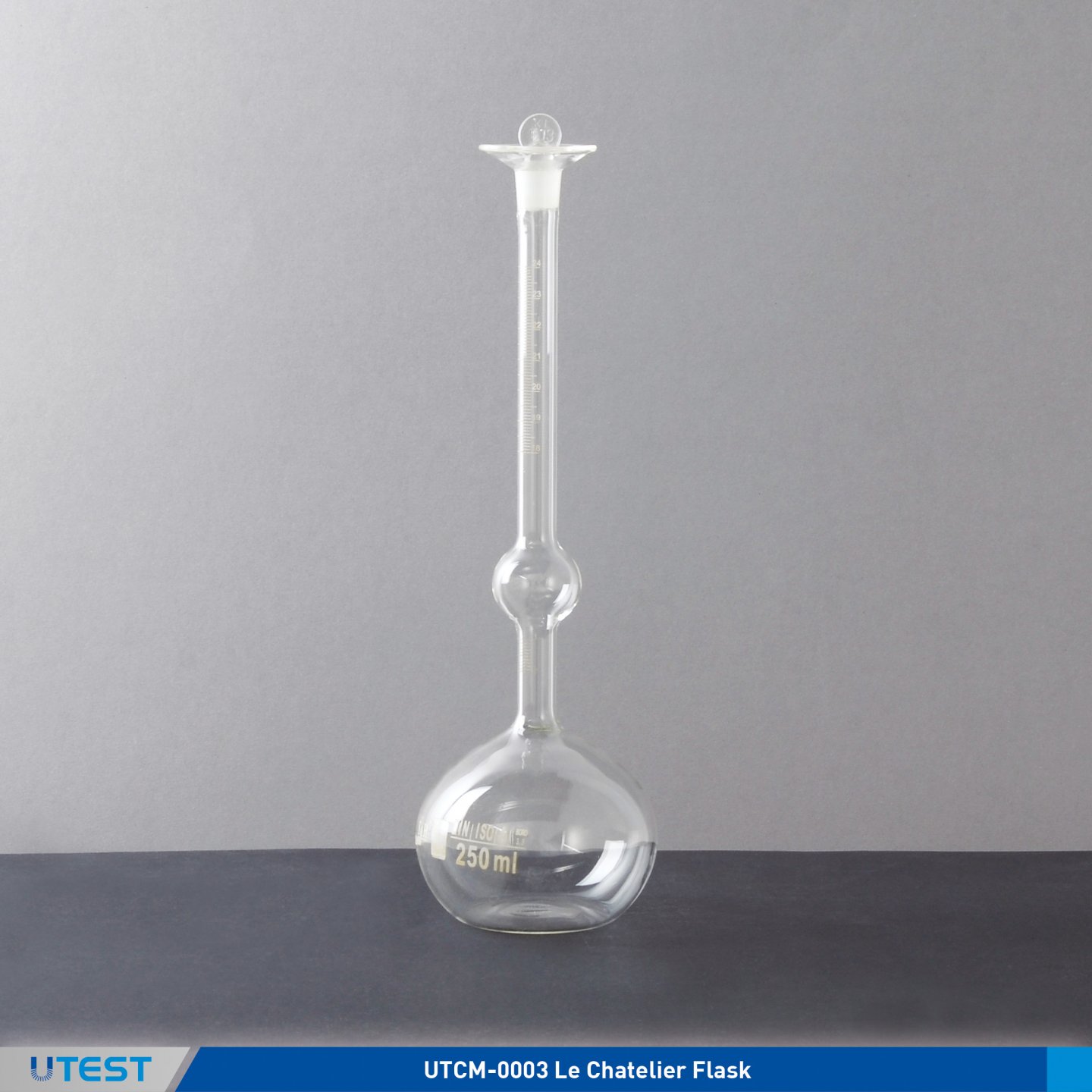
Product Code
|
UTCM-0003 |
Le Chatelier Flask |
Standards
EN 196-6, 450-1, 15617-1; ASTM C110, C128, C188; C989; AASHTO T133
The UTCM-0003 Le Chatelier Flask is used to determine the density of hydraulic cement, ground granulated blast-furnace slag and fly ash for concrete, filler aggregates and lime.The glass flask has a 250ml capacity. The neck is graduated from 0 to 1 ml and from 18 to 24 mL in 0.1-mL graduations.
|
Dimensions |
100x100x300 mm |
|
Weight (approx.) |
0.1 kg |
3. Le Chatelier Mould

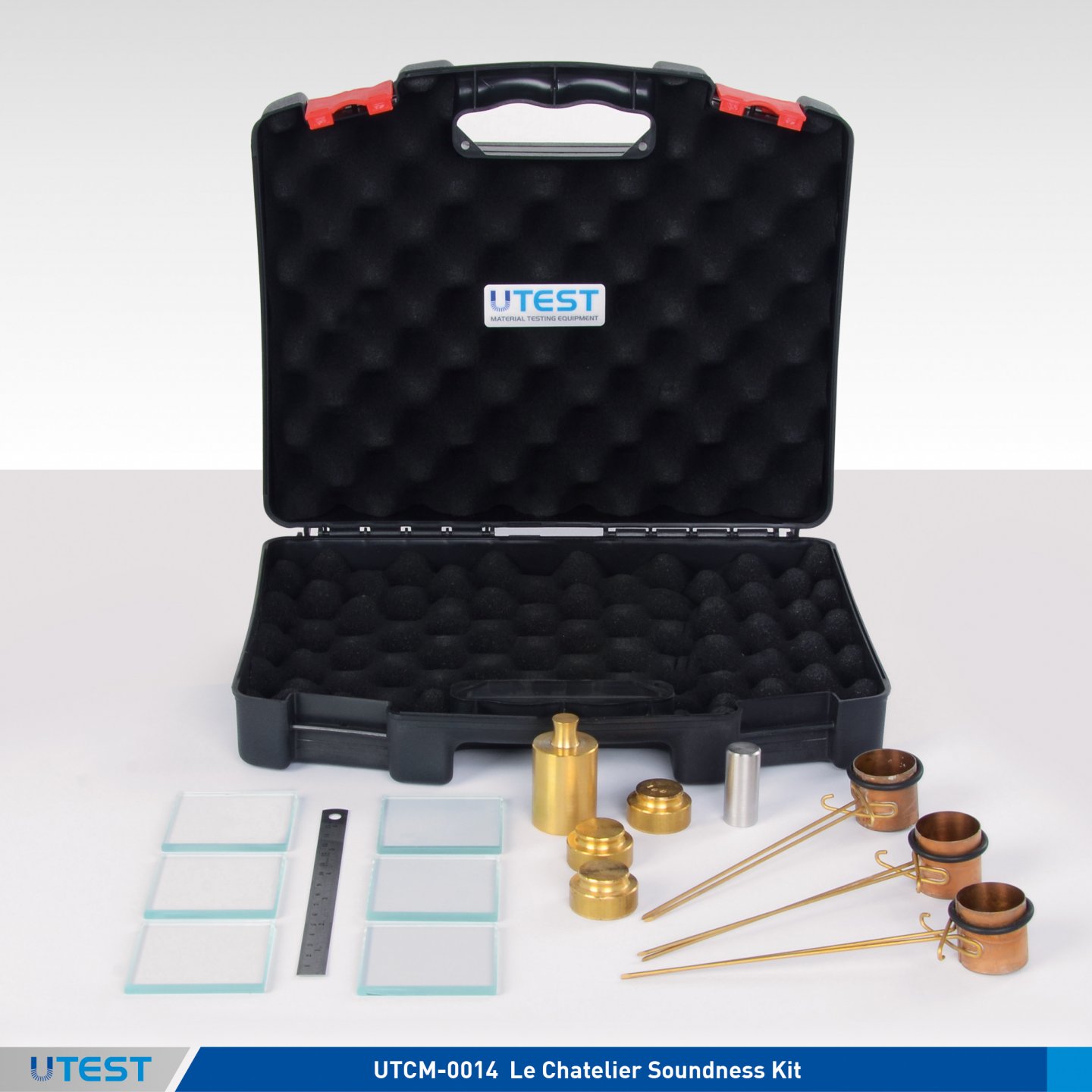
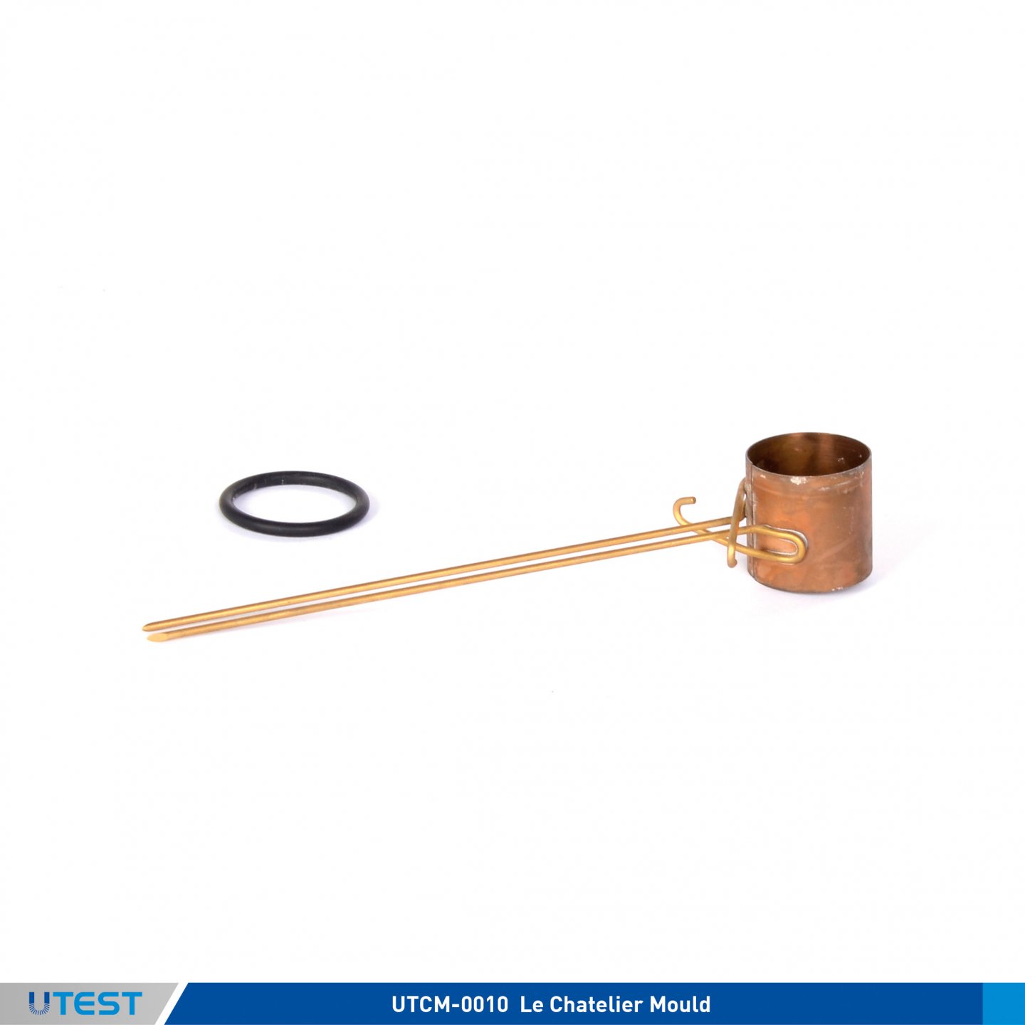
Product Code
|
UTCM-0010 |
Le Chatelier Mould |
|
UTCM-0014 |
Le Chatelier Soundness Kit |
Standards
EN 196-3, 450-1, 459-2; EN ISO 9597
The soundness of cement, fly ash for concrete and lime is determined by using the Le Chatelier moulds and Le Chatelier Water Bath (UTCM-0016) according to the relevant standard.
The Le Chatelier Soundness Kit is supplied complete with;
- Le Chatelier moulds 3 pcs.
- 50x50 mm glass plates 6 pcs.
- 300 gr Weights 1 pcs.
- 100 gr Weight, 3 pcs.
- Tamping Rod 17 mm dia. x 70 gr
- Steel Ruler
- Plastic Carrying Case
|
Dimensions |
340x290x80 mm |
|
Weight (approx.) |
2 kg |
4. Le Chatelier Water Bath
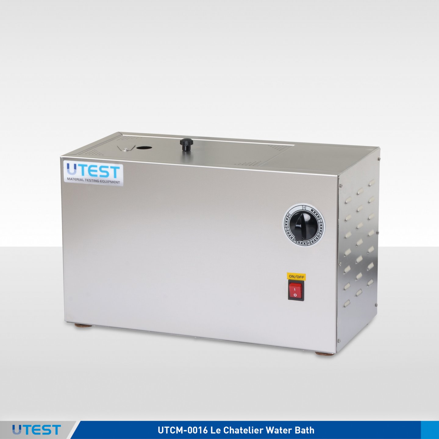
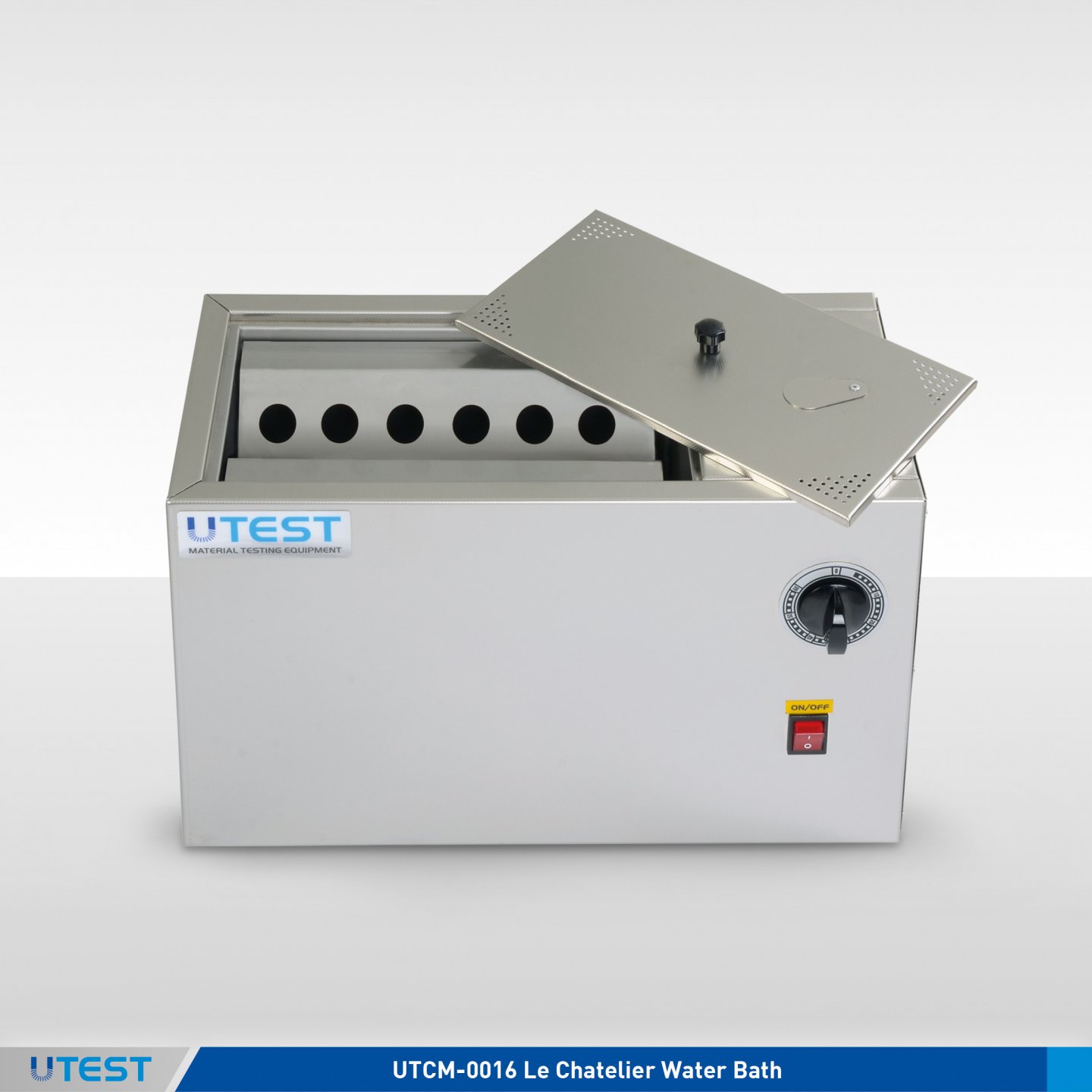
Product Code
|
UTCM-0016 |
Le Chatelier Water Bath |
|
Models for 220-240 V 50-60 Hz, 1ph. |
UTCM-0016 |
|
Models for 110-120 V 60Hz, 1ph. |
UTCM-0016-N |
Standards
EN 196-3, 450-1, 459-2; EN ISO 9597
The UTCM-0016 Le Chatelier Water Bath is used with Le Chatelier moulds for the determination of the soundness of cement paste fly ash for concrete and lime. The internal chamber and the insulated exterior case of the bath are manufactured from stainless steel. The Bath is capable of reaching boiling point in 30 minutes by using two heater units. There is a timer on the UTCM-0016 Le Chatelier Water Bath which is used to set the time for reaching the boiling point. After that time the temperature of water is regulated by using one heater unit to conserve energy. Supplied complete with a removable rack to hold up to 12 moulds. A cover is also supplied as standard.
Le Chatelier Moulds are should be ordered separately.
|
Dimensions |
210x470x290 mm |
|
Weight (approx.) |
8 kg |
|
Power |
1250 W |
5. High Pressure Cement Autoclave
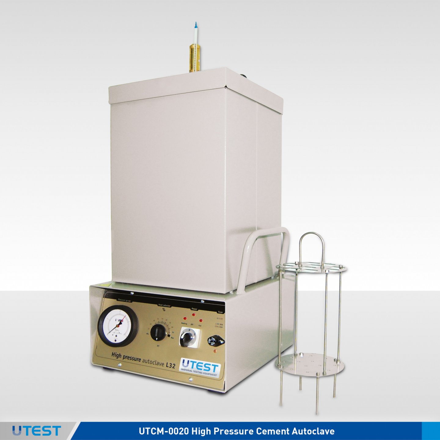
Product Code
|
UTCM-0020 |
High Pressure Cement Autoclave, 230 V 50-60 Hz, 1ph |
Standards
ASTM C151, C490; UNE 7207
The UTCM-0020 High Pressure Cement Autoclave is designed to perform expansion tests on cement specimens.10 specimens can simultaneously be tested in the high pressure steam vessel of 154 mm diameter and 430 mm height.
The Autoclave consists of a pressure gauge, pressure regulator, temperature regülatör, control switches safety valve and specimen rack. Certified conforming to INAIL procedure.
UTCM-0033A Two Gang Shrinkage mould and Length Comparators (UTCM-0200 or UTCM-0210) should be ordered separately.
The High Pressure Cement Autoclave is supplied complete with;
- Specimen Rack, 10 samples capacity
|
Dimensions |
450x475x1080 mm |
|
Weight (approx.) |
55 kg |
|
Power |
2600 W |
6. Length Change (Shrinkage And Expansion)
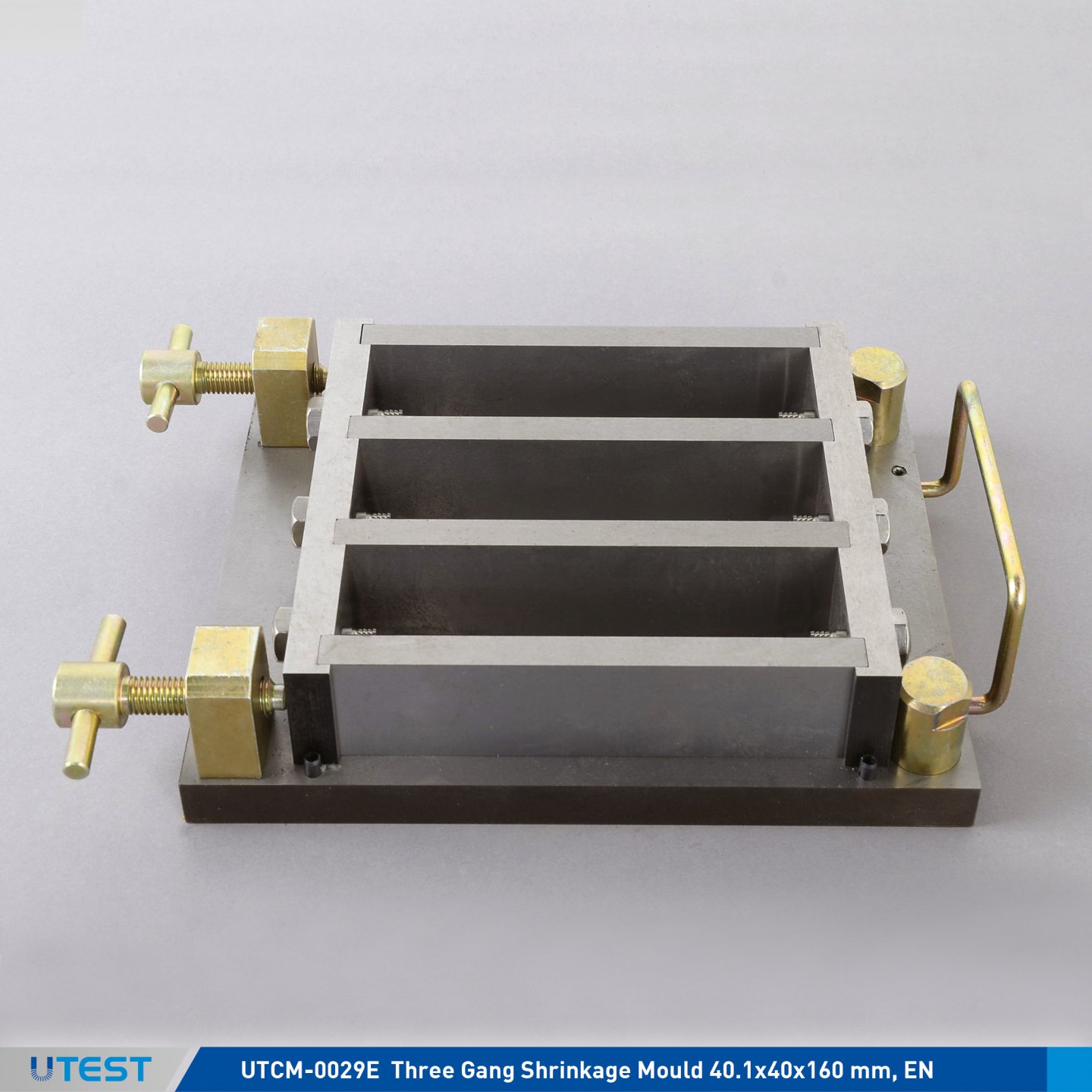
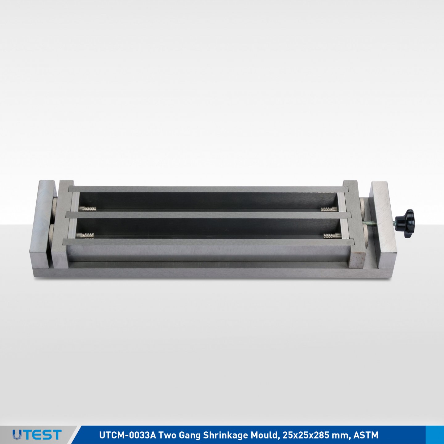
Product Code
|
UTCM-0029E |
Three Gang Shrinkage Mould 40.1x40x160 mm, EN, Minimum Hardness HV 400 |
|
UTCM-0030E |
Spare Steel Insert, EN, for UTCM-0029E, 18 pieces/pack |
|
UTCM-0031E |
Reference Rod, 160 mm Long with 6mm Tips |
|
UTCM-0031A |
Reference Rod, 170 mm Long with 6mm Tips |
|
UTCM-0032E |
Tamper, Hardwood, 38x15x200mm, 250 g, EN |
|
UTCM-0033A |
Two Gang Shrinkage Mould, 25x25x285 mm, ASTM |
|
UTCM-0034 |
Spare Steel Insert, ASTM C490, 12 pieces/pack |
|
UTCM-0035 |
Reference Rod, 295 mm Long with 6mm Tips |
|
UTCM-0140A |
Two Gang Expansion Mould, 50x50x285 mm |
|
UTCM-0154E |
Insert Set for UTCM-0029E, polyethylene (6 pcs.-15x40x160mm) |
|
UTCM-0662A |
Tamper, Hardwood, 13x25x150mm |
|
UTC-0410 |
Tamping Rod, Ø:10x300 mm |
Standards
ASTM C151, C452, C490, C596, C806, C1293; EN 12617-4, 12808-4
The moulds are used for preparpmg the specimens for the purpose of determining the length changes (shrinkage/expansion) in hardened hydraulic cement mortar and concrete.
According to all standardized test methods for determinig the length changes of hardened cement paste, mortar under different conditions, the muolds are used together with the any UTEST Length Comparators (UTCM-0200 or UTCM-0210) fit the specimens sizes.
Minimum surface hardness of UTCM-0029E is HV400 which is recommended by the EN standard.
All metal moulds surfaces are protected with anti-corrosion oil and all parts of them are matchmarked.
The moulds are supplied complied with the steel inserts screwed on.
Reference rod and other equipment be should ordered separately.
For the purpose of determining the length changes (shrinkage/expansion) in hardened concrete including aggregate which has larger sized Dmax, UTC-1153, UTC-1155 or UTC-1161 moulds are also used togerher with UTC-1170 Large type digital length comparator.
|
Product Code |
UTCM-0029E |
UTCM-0033A |
UTCM-0140A |
|
Dimensions |
300x190x70 mm |
390x100x45 mm |
390x160x70 |
|
Weight (approx.) |
12 kg |
7 kg |
18 kg |
7. Length Comparators

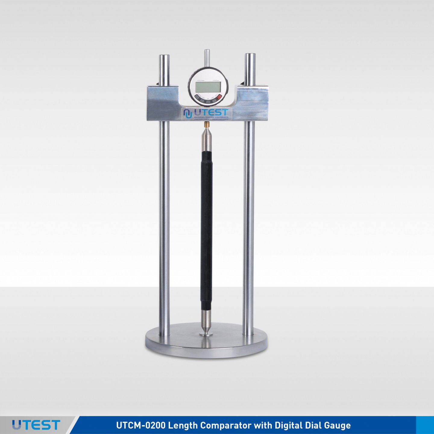
Product Code
|
UTCM-0200 |
Length Comparator with Digital Dial Gauge |
|
UTCM-0210 |
Length Comparator with Heidenhain Length Measuring Sensor and Digital Readout Unit |
|
UTC-1170 |
Large Type Length Comparator with Digital Dial Gauge |
|
UTC-1175 |
Large Type Length Comparator with Heidenhain Length Measuring Sensor and Digital Readout Unit |
Standards
EN 1367–4, 12617–4, 12808-4; ASTM C151, C157, C227, C311, C341,
C342, C441,C452, C490, C531, C596, C806, C878; BS 1881:5, 6073
Length Comparators are used to determine the length changes on different type of hardened mortar and concrete prisms with different sized.
The sets consist of a length measuring frame with measuring device attached to it. The comparators come with 4 different models, UTCM-0200 and UTC-1170 are with 0.001 mm x 12,7 mm digital dial gauge and UTCM-0210 and UTC-1175 are with special 0.0001 mm x 25 mm transducer and readout unit.
Horizontal clearance of UTCM-0200 is and UTCM-0210 are 145mm, UTC-1170 and UTC-1175 are is 220mm. Adjustable beam height (without digital dial gauge and adapter set) is 365 mm for all type.
All information about shrinkage moulds, steel inserts and reference rods can be seen on pages of UTCM-0029E, UTCM-0033A, UTA-0850, UTC-1153, UTC-1155 and UTC-1161.
The Length Comparators are supplied complete with 3 pcs. adapter sets (compatible with referance rods and inserts).
Reference rods and moulds should be ordered separately according to test to be performed.

UTCM-0210
|
Product Code |
Dimensions |
Weight (approx.) |
|
UTCM-0200 |
180x180x450 mm |
6 kg |
|
UTCM-0210 |
250x250x640 mm |
8 kg |
|
UTC-1170 |
250x250x650 mm |
8 kg |
|
UTC-1175 |
250x350x650 mm |
9 kg |
8. Automatic Blaine Air Permeability Apparatus
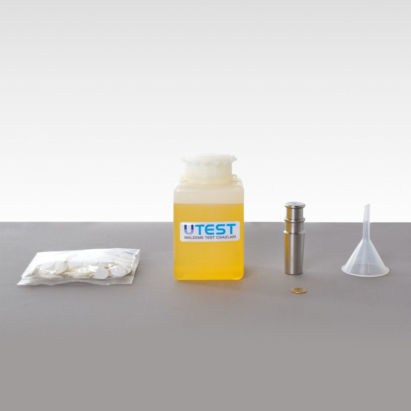
Product Code
|
UTCM- 0280 |
Automatic Blaine Air Permeability Apparatus, 110-230V, 50-60 Hz, 1ph |
|
UTCM- 0242 |
Manometer Liquid 250 ml |
|
UTCM- 0243 |
Cell with Perforated Disc and Plunger |
|
UTCM- 0244 |
Filter Paper 100 pcs. |
|
UTCM- 0245 |
Filter Paper 1000 pcs. |
|
UTCM- 0246 |
Reference Cement 5 g, ASTM |
|
UTCM- 0282 |
Reference Calibration Sand – Fine, Approx. 100g |
|
UTCM- 0284 |
Reference Calibration Sand - Coarse, Approx. 100g |
Standards
EN 196-6; ASTM C204; BS 4550
The UTCM- 0280 Automatic Blaine Air Permeability Apparatus perform the test for determining the fineness of cements, limes and similar powders expressed in terms of their specific surface according to the above testing standards. The fineness of cement can be automatically measured as specific surface by observing the time taken for a fixed quantity of air to flow through a compacted cement bed of specified dimensions and porosity.The method is comparative rather than absolute and therefore a reference sample of known specific surface is required for calibration of the apparatus.
Main Features
- The test is controlled on the touch screen.
- Automatic control of the movement of fluid until the upper line
- Automatic measurement of the air flow time
- Automatic measurement of temperature during the test
- Languages (English, Spanish, Russian, Turkish)
Reference Cement and Reference Calibration Sands should be ordered separately.
|
|
UTCM-0282 |
UTCM-0284 |
|
Specific surface (aporox. cm2/g) |
3890 |
2980 |
|
Density (aporox. 2,65 g/cm3) |
2,65 |
2,65 |
|
Porosity (aporox.) |
0,50 |
0,50 |


UTCM-0280 is supplied complete with;
- Manometer Liquid, 250 ml
- Cell with Perforated Disc and Plunger (with UTEST Certıfıcate of Cell And Plunger Dimensions for Calculation of Cell Specimen Volume)
- Plastic Funnel
- Filter Paper, 100 pcs
|
Dimensions |
240x420x450 mm |
|
Weight (approx.) |
16 kg |
9. Blaine Air Permeability Apparatus
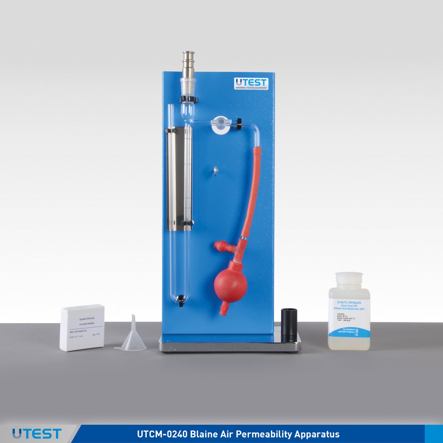
Product Code
|
UTCM-0240 |
Blaine Air Permeability Apparatus |
|
UTCM-0241 |
U Manometer Tube |
|
UTCM-0242 |
Manometer Liquid 250 ml |
|
UTCM-0243 |
Cell with Perforated Disc and Plunger |
|
UTCM-0244 |
Filter Paper 100 pcs. |
|
UTCM-0245 |
Filter Paper 1000 pcs. |
|
UTCM-0246 |
Reference Cement 5 g, ASTM |
|
UTCM- 0282 |
Reference Calibration Sand – Fine, Approx. 100g |
|
UTCM- 0284 |
Reference Calibration Sand - Coarse, Approx. 100g |
Standards
EN 196-6; ASTM C204; AASHTO T153
The UTCM-0240 Blaine Air Permeability Apparatus is used to determine the fineness of Portland cement, limes and similar powders expressed in terms of their specific surface.
UTCM-0246 Reference cement, UTCM-0282 and UTCM-0284 reference calibration sands should be ordered separately.
The Blaine Air Permeability Apparatus is supplied complete with;
- U Manometer Tube
- Manometer Liquid, 250 ml
- Test Stand
- Rubber Aspirator
- Cell with Perforated Disc and Plunger (with UTEST Certıfıcate of Cell And Plunger Dimensions for Calculation of Cell Specimen Volume)
- Plastic Funnel
- Filter Paper, 100 pcs.
|
|
UTCM-0282 |
UTCM-0284 |
|
Specific surface (aporox. cm2/g) |
3890 |
2980 |
|
Density (aporox. 2,65 g/cm3) |
2,65 |
2,65 |
|
Porosity (aporox.) |
0,50 |
0,50 |
|
Dimensions |
300x540x210 mm (packed) |
|
Weight (approx.) |
7 kg (packed) |
10. Heat of Hydration Calorimeter with High Resolution D. Th.
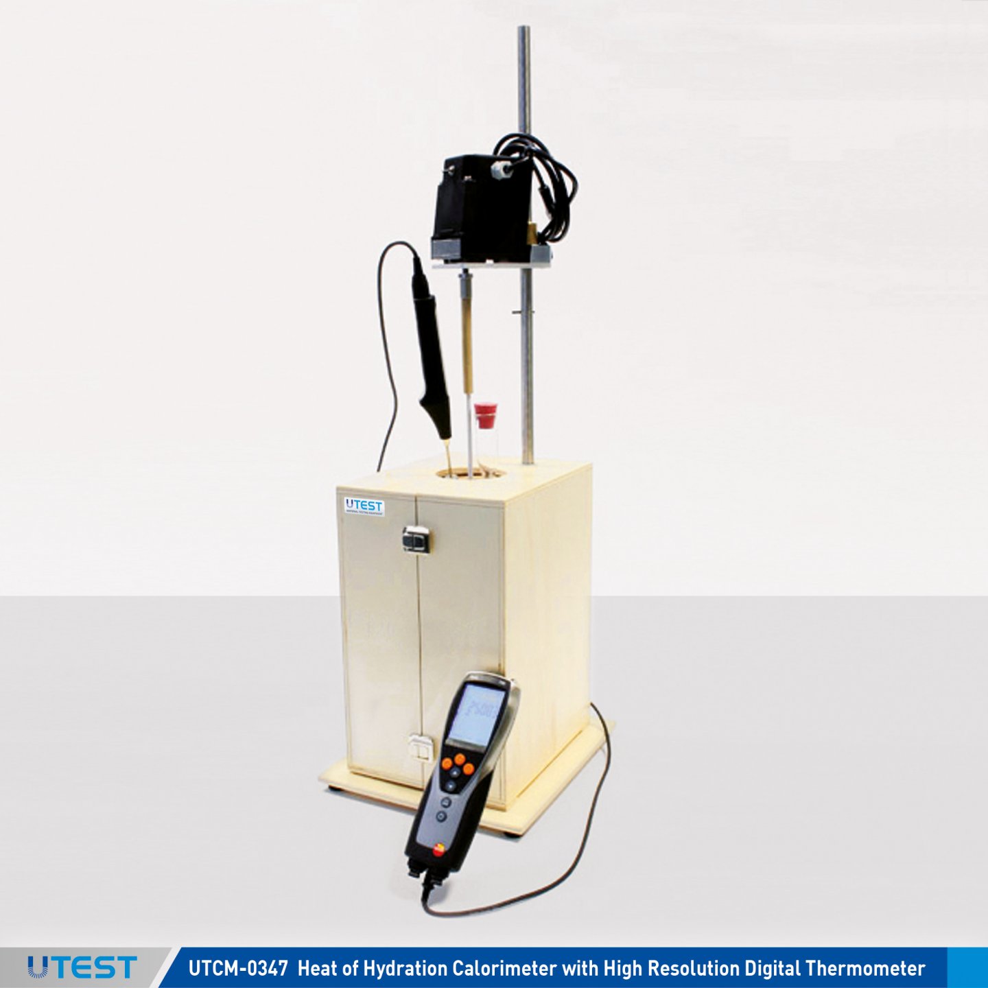
Product Code
|
UTCM-0347 |
Heat of Hydration Calorimeter with High Resolution Digital Thermometer, 230 V, 50-60 Hz, 1 ph |
Standards
EN 196-8; ASTM C186
When Portland or hydraulic cement is mixed with water, heat is generated as a result of the exothermic reaction. The heat generated by cement’s hydration raises the temperature of concrete and this temperature rise causes expansion while concrete is hardening, especially under conditions when heat can not be readily released.
The UTCM-0347 Heat of Hydration Calorimeter is used for determining the heat of hydration of low heat Portland and hydraulic cement. The apparatus consists of a Dewar flask housed in an insulated box, an electric stirrer, a filler funnel and a high resolution battery operated electronic thermometer.
Features
- Displays, saves and prints ΔT, Min., Max. and Mean Values
- Audible alarm if limit values are exceeded
- Resolution 0.001°C
- PT100 Probe Measuring Range -40 to +300°C
- Protection class IP65
- Accuracy 0.05°C
- Memory 10.000
- Complete with resolution test certificate
- Supplied complete with MS EXCEL template for data processing
|
Dimensions |
300x200x650 mm |
|
Weight (approx.) |
13 kg |
11. Muffle Furnace
Product Code
|
UTD-1462 |
Muffle Furnace 6 lt. 1200°C Max. Temperature with Programmable Timer, 20-240 V 50-60 Hz |
Standards
EN 196-2; ASTM C25, C115
UTD-1462 Muffle Furnace is used for determining the loss on ignition and insoluble residue of cement and building lime.
Working temprature and time can be programmed with PID digital control system.
Digital Thermometer Features
|
Temperature Controller |
PC 442/2 |
|
Max. Temperature |
1200 °C |
|
Max. Continuous Temperature |
1150 °C |
|
Temperature Deviation at Set Point |
± 2°C |
|
Heat Up Time to Max. Temperature |
50. min |
|
Internal Volume |
6 L |
|
Phase |
1 |
|
Internal Dimension |
140x180x200 mm |
|
External Dimension |
650x550x580 mm |
|
Weight (approx.) |
56 kg |
|
Power |
2000 W |
12. Vicat Test Sets
Product Code
|
UTCM-0451 |
Vicat Apparatus |
|
UTCM-0452E |
Vicat Mould EN Base ID 80 mm, Top ID 70 mm, Height 40 mm |
|
UTCM-0452A |
Vicat Mould ASTM Base ID 70 mm, Top ID 60 mm, Height 40 mm |
|
UTCM-0453E |
Initial Vicat Needle EN 1.13 mm dia. |
|
UTCM-0453A |
Vicat Needle ASTM 1 mm dia. |
|
UTCM-0454E |
Final Vicat Needle EN 1.13 mm dia. |
|
UTCM-0455 |
Consistency Plunger 10 mm dia. |
|
UTCM-0458E |
Transfer Dish for UTCM-0451 |
|
UTGT-1305 |
Glass Thermometer Max. 110°C |
|
UTCM-0457 |
Additiniol Weight, 700 gr, EN 480-2 |
Standards
EN 196-3, 480-2; ASTM C187, C191; AASHTO T129, T131
The Vicat test equipment is used for determining the setting time and consistency of cement by Vicat Method.
Vicat Apparatus consist of metal frame with a scale, Ø10mm consistency plunger and supporting glass plate.
The needle/s, mould, thermometer and transfer dish (for EN) should be ordered seperately.

UTCM-0453A UTCM-0455 UTCM-0453E UTCM-0454E
|
Dimensions |
150x190x318 mm |
|
Weight (approx.) |
3 kg |
13. Automatic Vicat Apparatus VICAMATIC-3
Product Code
|
UTCM-0550E |
Automatic Vicat Apparatus (VICAMATIC-3) EN, 110-240 V 50-60 Hz, 1ph |
|
UTCM-0550A |
Automatic Vicat Apparatus (VICAMATIC-3) ASTM, 110-240 V 50-60 Hz, 1ph |
Standards
EN 196-3, 13279-2, 480-2; ASTM C191, C187; AASHTO T131
The setting time determination of cement/mortar/gypsum is one of the most important parameter for the quality inspection and verification. The new generation automatic setting time tester is now available, featuring a large color 5.1” touch screen display, a needle (or a probe) drops freely into a cement sample at regular intervals and in fixed positions. Along with hardening process development the penetration depth decreases, when it matches some thresholds pre-defined by standards initial and final setting times are measured and recorded.
Main Features
• Advanced electronics technologies providing superior performances and total flexibility combined with simplicity in use
• Easy-to-use double interface: local mode, with large size 5,1" touch screen color display and remote mode with PC
• Supplied complete with PC software for data processing VICASOFT-BASIC
• With PC software VICASOFT-PREMIUM (optional) up to 32 indipendent units (includign VICAMATIC 2 models) can be connected to a single PC via LAN port and hub. All units are remotely controlled. Adopting the multi-test network concept laboratory productivity is maximized
• Integrated graphic printer is available as optional accessory showing both results in numerical format and setting time plot
• Easy setting and storage of user-defined test profiles allowing quick test start
• Large accessibility to the test space
• Complete with needle cleaning device
• Practical in-water testing accessory (optional)
• Automatic determination of initial and final setting time
• Penetration depth is measured by a sensor with 0,1 mm resolution.
Technical Specification
• Conforming to EN 196-3, 13279-2, 480-2, ASTM C191, C187
• 5.1”, 800 x 480 pixel, 16 M colors, icon-driven touchscreen graphic display, showing data and plots
• LAN port for direct connection to PC of a single unit or connection to a LAN hub for creating a network with up to 32 independent units all controlled by a single PC. 1 LAN cable is included
• USB port for data download to PC and easy firmware upgrade
• Unlimited storage capacity for test data on internal 16 GB SD card
• Test procedures can be customized and stored to match user-defined requirements
• Can incorporate an integrated graphic printer showing test result and setting time plot
• Large test space with easy accessibility
• Automatic calculation of initial and final setting time at programmable penetration depth limits
• Wide range of accessories including EN and ASTM/AASHTO parts, in-water testing kit, needle cleaning device, integrated printer, probes for testing consistency and gypsum
• Minimum penetrations rate: 10 seconds
• Penetration measurement by encoder
Firmware Specifications
• Easy programming of customized test profiles, recallable for future tests, including:
• adjustable test start delay
• penetration points positions
• manual or automatic penetration rate
• free or driven dropping mode
• holding intervals inside the sample
• automatic end - test detection
• automatic measurement of initial and final setting time
• Test data: test number, operator, client, date, hour, cement type, water percentage, delay
• Easy calibration menu
• Clock calendar
• Multi-language
Accessories
UTCM-0552 LAN hub for PC connection of up to 7 VICAMATIC- 2 units or up to 6 units in case of multi-hub network. LAN cable from hub to PC is included. Each VICAMATIC-2 unit is supplied complete with LAN cable.
UTCM-0553 Upgrading of a VICAMATIC-2 unit for incorporating a graphic printer into the head. Test settings and results are plotted both as numerical and graphical format including penetration depth/time diagram. The upgrading shall be factory installed.
UTCM-0559 VICASOFT-PREMIUM Software for PC connection of up to 32 VICAMATIC-2 and VICAMATIC-3 units including remote control of each unit, data acquisition - processing - filing, printout of test reports.
Communication via LAN port (each VICAMATIC-3 unit is supplied complete with LAN cable). The connection of one unit is direct via the PC LAN-port, for more units (up to 32) one or more LAN hubs are required with total number of ports equal (or bigger) to the number of units included in the network. LAN hubs are not included
Accessories to EN Standards
UTCM-0551 Accessory for Needle Cleaning and In-Water Testing
UTCM-0554 Needle for Final Setting Test EN 196-3
UTCM-0555 Cylindrical Probe for Consistency Test
UTCM-0556 Additional Weight 700 g to EN 480-2
UTCM-0557 Water thermostatic unit for VICAMATIC. Up to 2 units may be connected. 230 V, 50-60 Hz, 1 ph.
UTCM-0557-N Same as UTCM-0557, but 110 V, 60 Hz, 1 ph
UTCM-0558 Conical penetration probe 8 mm dia x 50 mm complete with 100g calibrated weight for gypsum testing to EN 13279
Accessories to ASTM Standards
UTCM-0555 Cylindrical Probe for Consistency
UTCM-0566 Cylindrical probe and addition weight for consistency test to ASTM C807.
UTCM-0567 2 mm dia. needle to ASTM C807
UTCM-0568 Brass cylindrical mould to ASTM C807
Spare Parts
UTCM-0560 1,13 mm dia. needle for initial setting time test to EN
UTCM-0561 1 mm dia. needle for setting time test to ASTM/AASHTO
UTCM-0562 Plastic mould to EN
UTCM-0563 Plastic mould to ASTM/AASHTO
UTCM-0564 Glass base plate
UTCM-0565 Spare base plate for in-water testing kit
UTCM-0571E Centering ring for EN vicat mould
UTCM-0571A Centering ring for ASTM vicat mould
- UTCM-0550E is supplied complete with EN 196-3 accessories: initial setting time needle 1.13 mm dia, mould and PC software VICASOFT-BASIC.
- UTCM- 0550A is supplied complete with ASTM C191 accessories: setting time needle mm dia, mould and PC software VICASOFT-BASIC.
Other accessories should be ordered separately for the tests.
|
Power |
50 W |
|
Dimensions (LxWxH) |
200x400x410 mm |
|
Weight (approx.) |
10 kg |
14. Gillmore Apparatus
Product Code
|
UTCM-0578 |
Gillmore Apparatus |
Standards
ASTM C266; AASHTO T154
The UTCM-0578 Gillmore Apparatus is used to determine the setting time of cement hydraulic hydrometer lime and mortar. Apparatus consists of two horizontally positioned arms, carrying weighted needles, initial needle has a 2.12 mm diameter and 113.4 g in weight and the final needle has a 1.06 mm diameter and 453.6 g in weight.
Supplied complete with two glass plates.
|
Dimensions |
300x100x300 mm |
|
Weight (approx.) |
2,5 kg |
15. Flow Table
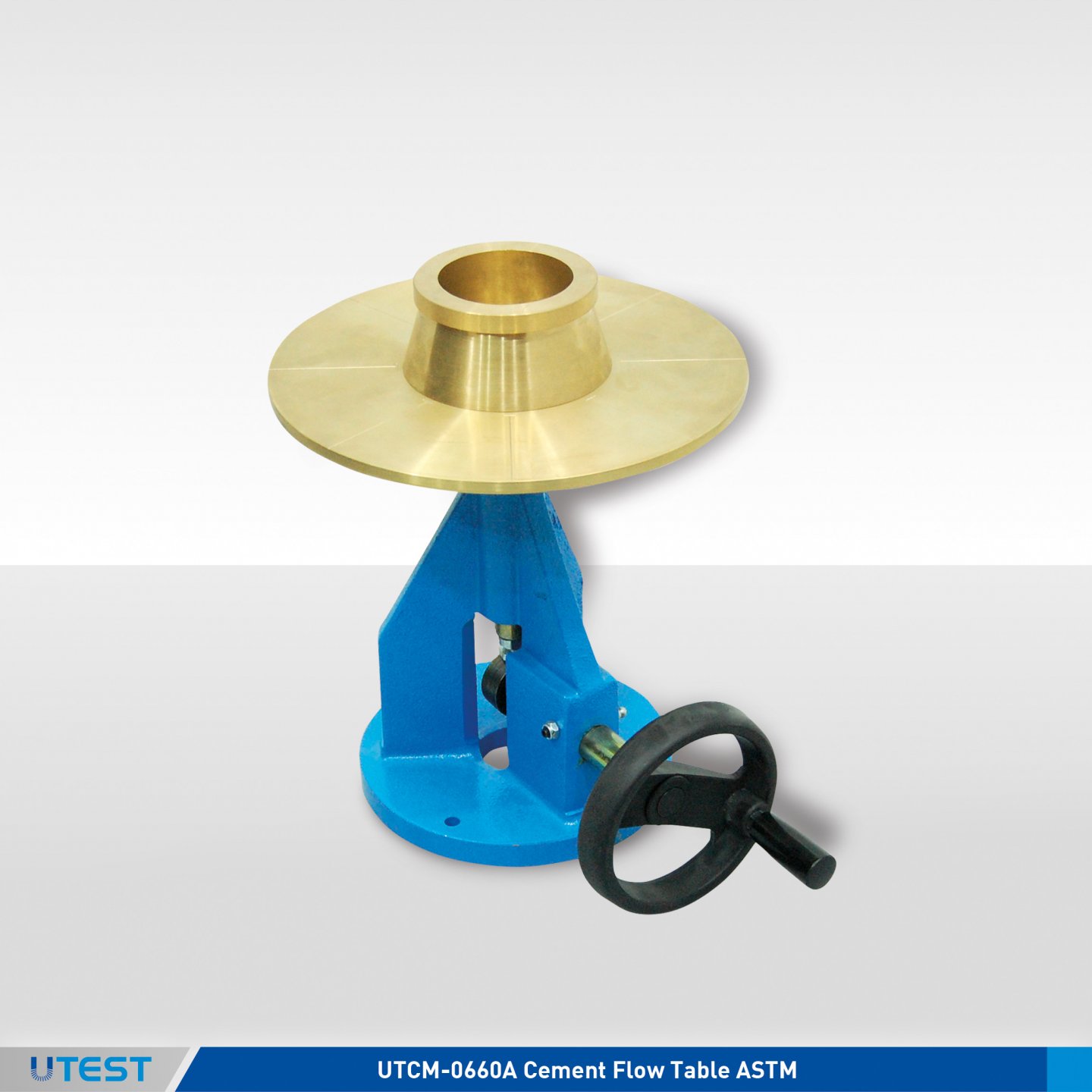
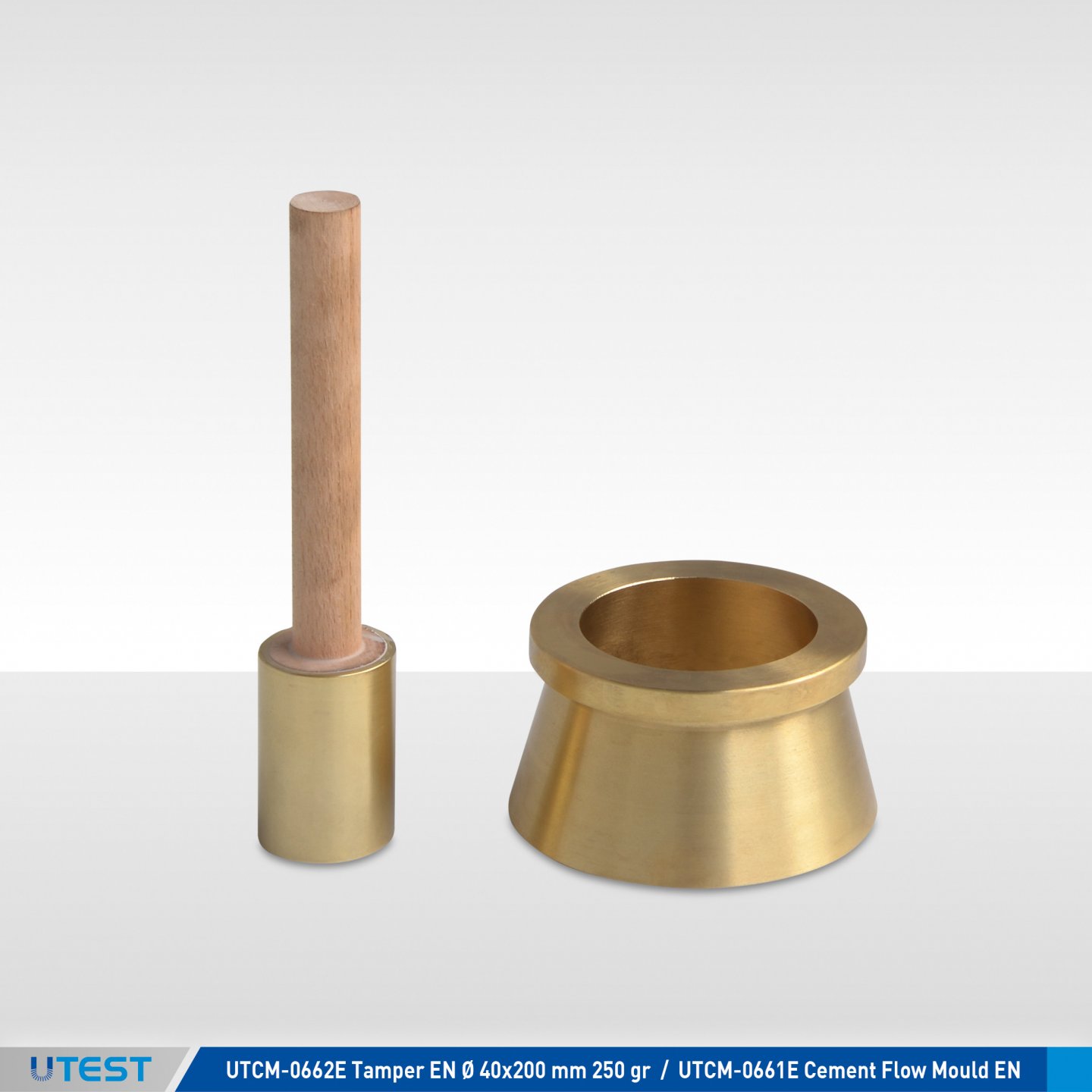
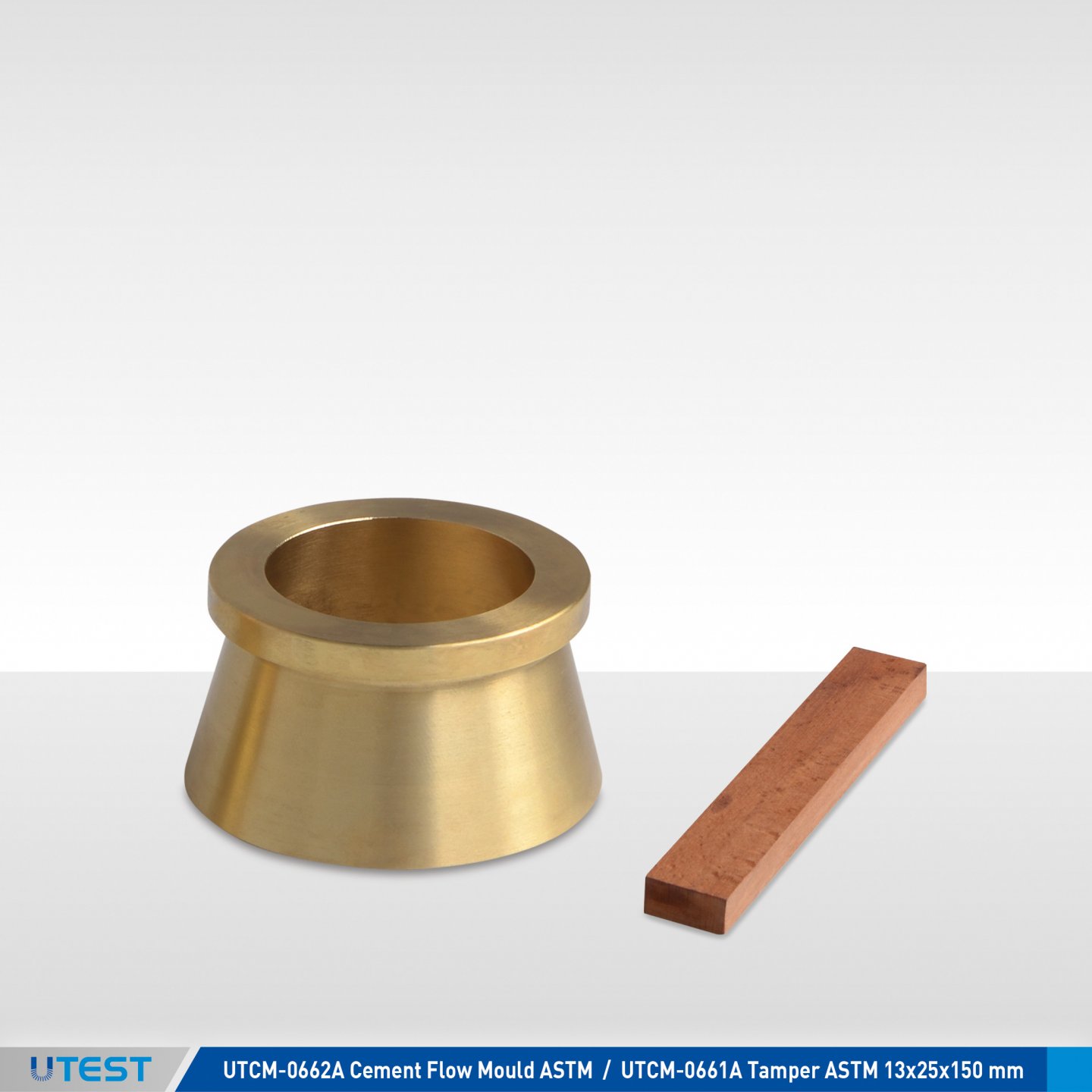
Product Code
|
UTCM-0660A |
Cement Flow Table ASTM, Metric |
|
UTCM-0661A |
Cement Flow Mould ASTM, Metric |
|
UTCM-0662A |
Tamper ASTM Hardwood 13x25x150 mm |
|
UTCM-0663A |
Motorized Cement Flow Table ASTM |
|
UTCM-0660E |
Cement Flow Table EN |
|
UTCM-0661E |
Cement Flow Mould EN |
|
UTCM-0662E |
Tamper EN Ø 40x200 mm 250 gr |
|
UTCM-0663E |
Motorized Cement Flow Table EN |
|
Models for 220-240V 50-60 Hz, 1 ph. |
UTC-0663A |
UTC-0663E |
|
Models for 110-120V 60 Hz, 1 ph. |
UTC-0663A-N |
|
Standards
ASTM C230; EN 459-2, 1015-3
There are two models of the Cement Flow Table according to ASTM and EN standard. Both are used for determining the consistency of mortar, lime and cement specimens. Also manual and motorized models are available.
The hand operated model is fitted with a hand wheel. The motor operated model is driven by a motor speed reducer through a mechanical coupling at the rate of 1 revolution per second. The number of drops is preset on a counter and the machine stops automatically at the end of the cycle.
EN model, the table is manufactured from stainless steel and has a 300 mm diameter table. The conical mould is made of stainless steel and has dimensions of 100 mm base dia. x 70 mm top dia. x 60 mm height.
ASTM model; the table is manufactured from bronze and has 254 mm diameter. The conical mould is made of brass has dimensions of 100 mm base dia. X 70 mm top dia. X 50 mm height.
Both models are supplied complete with mould and tamper. EN model also has a stainless steel hopper.

UTCM-0660E UTCM-0660A UTCM-0662A - UTCM-0661A UTCM-0662E - UTCM-0661E
|
|
UTCM-0660A UTCM-0663A ASTM |
UTCM-0660E UTCM-0663E EN |
|
Table Diameter |
254 mm |
300 mm |
|
Cone Base/Top Diameter |
100.0 mm /70.0 mm |
100.0mm /70.0 mm |
|
Cone Height |
50.0 mm |
60.0 mm |
|
Drop Height |
12.7 mm |
10.0 mm |
|
Power |
180 W ( Motorized ) |
|
|
Product Code |
Dimensions |
Weight (approx.) |
|
UTCM-0660A |
250x360x350 mm |
12,5 Kg |
|
UTCM-0660E |
300x400x350 mm |
20 |
|
UTCM-0663A |
400x450x400 mm |
35 |
|
UTCM-0663E |
450x560x300 mm |
34 |
16. Workable Life, Stiffening Time & Setting Time
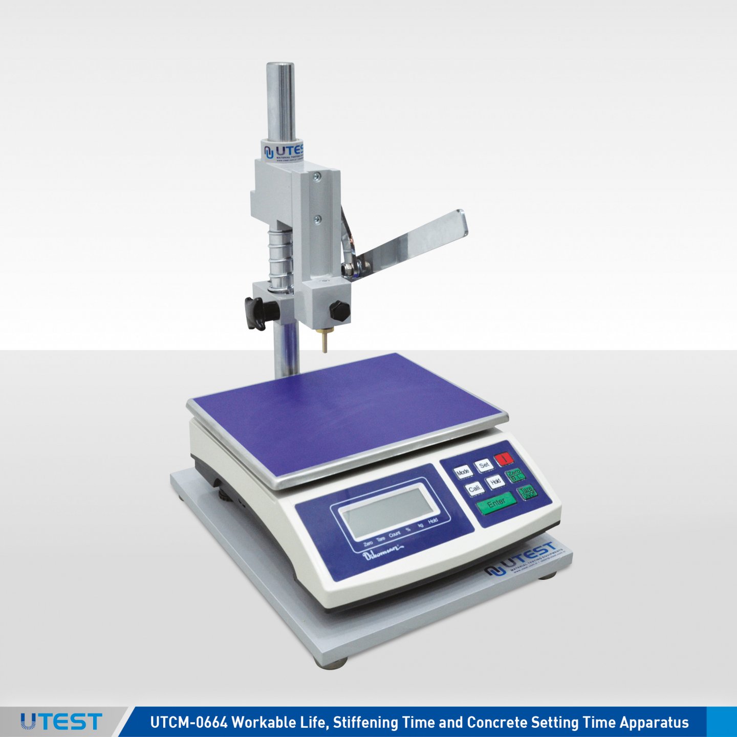
Product Code
|
UTCM-0664 |
Workable Life, Stiffening Time and Concrete Setting Time Apparatus |
|
UTW-0637 |
Digital Balance, 30 kg / 5 g. |
|
UTC-0705 |
Needle Set (645, 323, 161, 65, 32, 16 mm²) for UTCM-0064 |
|
UTW-0654 |
Digital Balance, 60 kg x10 gr |
Standards
EN 1015-9, 13294; ASTM C 403
The apparatus is used for determining the stiffening time of repair products and systems comprising hydraulic based mortar and concrete (CC), including those modified by the addition of polymers (PCC) and workable life of fresh mortar after the mixing procedures.
The Apparatus consist of a vertical loading pillar with a base. Supplied complete with a brass penetration rod with washer and a sample container (Ø80x80 mm aluminum).
UTC-0705 Needle Set for concrete setting time test acc.to ASTM should be ordered separately
UTW-0637 Digital Balance for the initial setting time, workable life and stıffening time should be ordered separately, as well.
Also, for determining concrete final setting time, instead of UTW-0637, UTW-0654 should be ordered separately.
|
Dimensions |
400x400x600 mm |
|
Weight (approx.) |
10 kg |
17. Manuel Mortar Mixers
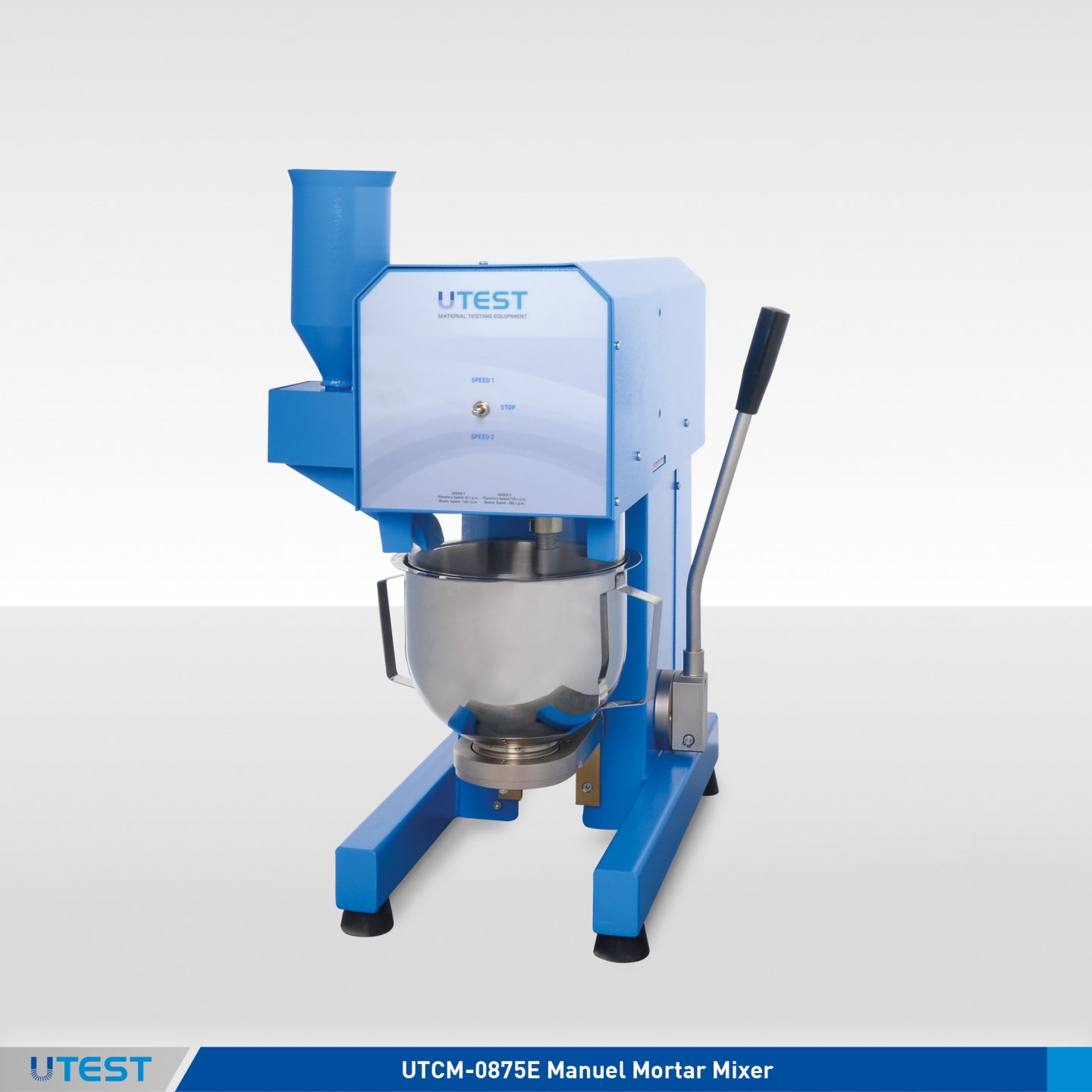
Product Code
|
UTCM-0875E |
Manuel Mortar Mixer, EN |
|
UTCM-0875A |
Manuel Mortar Mixer, ASTM |
|
UTCM-0876 |
Spare Bowl, 5 L |
|
UTCM-0878E |
Spare Beater, EN |
|
UTCM-0878A |
Spare Beater, ASTM |
|
Models for 220-240 V 50-60 Hz, 1ph. |
UTCM-0875E |
UTCM-0875A |
|
Models for 110-120 V 60Hz, 1ph. |
UTCM-0875E-N |
UTCM-0875A-N |
Standards
EN 196-1, 196-3, 413-2, 459-2, 480-1, 1015-2, 12617-4;
ASTM C187, C305, AASHTO T129, T131, T162
The UTCM-0875 Manual Mortar Mixer has a 5 liter (approx.) capacity, they have been designed to mix mortars and cement pastes primarily to the requirements of standards.
The mixing paddles revolve at a rate of 140 rpm. with a planetary motion of 62 rpm. in low speed. In high speed, the paddles revolve at the rate of 285 rpm. with a planetary motion of 125 rpm.
The user can choose the speeds easily by using the switch fitted to the machine. There is a sand filling apparatus on the mixers to pour sand easily. The bowl and beater are easily fitted and removed from mixer.
The Manual Mortar Mixers are supplied complete with;
- Bowl, 5 L (approx.)
- Beater

UTCM-0878E UTCM-0876
|
Dimensions |
300x555x610 mm |
|
Weight (approx.) |
54 kg |
|
Power |
200 W |
18. Automatic Programmable Mortar Mixer
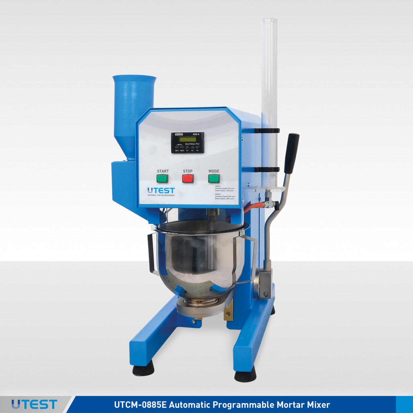
Product Code
|
UTCM-0885E |
Automatic Programmable Mortar Mixer |
|
UTCM-0885A |
Automatic Programmable Mortar Mixer |
|
UTCM-0876 |
Spare Bowl, 5 L |
|
UTCM-0878E |
Spare Beater, EN |
|
UTCM-0878A |
Spare Beater, ASTM |
|
Models for 220-240 V 50-60 Hz, 1ph. |
UTCM-0885E |
UTCM-0885A |
|
Models for 110-120 V 60Hz, 1ph. |
UTCM-0885E-N |
UTCM-0885A-N |
Standards
EN 196-1, 196-3, 413-2, 459-2, 480-1, 1015-2, 12617-4; ASTM C187, C305; AASHTO T129, T131, T162
The mixers have been designed to mix mortars and cement pastes primarily to the requirements of standards. The mixing paddles have a planetary motion and is driven by a motor with a microprocessor based speed and preset programs to meet all listed EN and ASTM standards, custom designed programs or manual mode. The mode button is used for the fast selection of different programs.
The mixing paddles revolve at a rate of 140 rpm. with a planetary motion of 62 rpm. in low speed. In high speed, the paddles revolve at the rate of 285 rpm. with a planetary motion of 125 rpm. An automatic sand dispenser is supplied with the machine and the sand is automatically discharged. In custum mode, motor speed (62 rpm or 125 rpm), sand dispenser position and duration of the mix can be set by the operator. On the display the user can see the mix time and the machine is equipped with lamp in order to warn the user for critical time periods.
The Automatic Programmable Mortar Mixers are supplied complete with;
- Bowl, 5 lt (approx.)
- Beater
UTCM-0878E UTCM-0876
|
Dimensions |
300x555x610 mm |
|
Weight (approx.) |
56 kg |
|
Power |
200 W |
19. CEN Standard Sand
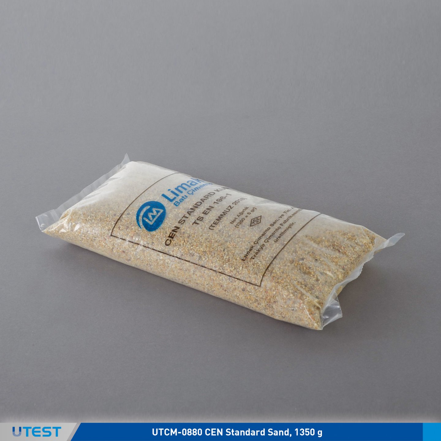
Product Code
|
UTCM-0880 |
CEN Standard Sand, 1350 gr |
Standards
EN 196-1
CEN Standard Sand CEN Standard Sand CEN Standard Sand CEN Standard Sand CEN Standard Sand
|
Dimensions |
300x190x70 mm |
|
Weight (approx.) |
1350 gr |
20. Jolting Table
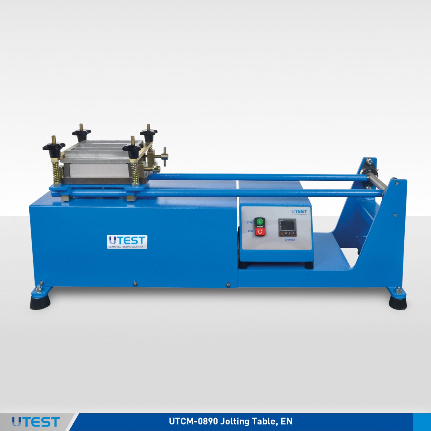
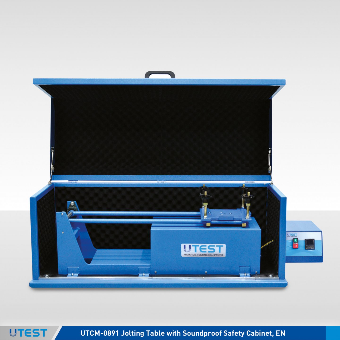
Product Code
|
UTCM-0890 |
Jolting Table, EN |
|
UTCM-0891 |
Jolting Table with Soundproof Safety Cabinet, EN |
|
UTCM-0892.2 |
Three Gang Mould for 40x40x160 mm, HV200 |
|
UTCM-0892.4 |
Three Gang Mould for 40x40x160 mm, HV400 |
|
UTCM-0893 |
Feed Hopper for UTCM-0892 |
|
UTCM-0894 |
Short and Long Spreaders and Straightedge, for UTCM-0892 |
|
Models for 220-240 V 50 Hz, 1ph. |
UTCM-0890-T |
UTCM-0891-T |
|
Models for 220-240 V 60 Hz, 1ph. |
UTCM- 0890-K |
UTCM- 0891-K |
Standards
EN 196-1; ISO 679
Jolting Table is used for compacting of cement specimens in 40x40x160 mm mould and consists of mould table seated on a rotating cam driven at 60 r.p.m. The falling height is 15 mm conforming to EN 196-1. The machine is equipped with a counter which provides automatic shut off at end of preset drop numbers.
Weight and dimensions of the jolting table fully comply with the requirements of EN 196-1 standard. When used with UTCM-0892 Three Gang Mould and UTCM-0893 Feed Hopper, the total weight of the moving part is 20 kg ± 0.5 kg. Without UTCM-0892 and UTCM-0893 the weight of the moving parts is 6.85 kg. Rapid mould lock and release system allows easy and quick operation.
The supporting frame of the machine has been designed to ensure precise dimensions, table flatness, correct centering of the three gang mould on the table.
The motor and gearbox assembly is enclosed in a protective housing, which promotes user safety (the moving parts are inaccessible) and long life for the gearbox.
The standard model can be supplied with a safety/noise reduction cabinet. The cabinet is lined internally with soundproofing material to reduce sound level conforming to CE directives.
UTCM-0893 Feed Hopper is used for filling UTCM-0892 Three Gang Moulds placed on the Jolting Table.
UTCM-0892 Three Gang Mould, UTCM-0893 Feed Hopper, UTCM-0894 Short and Long Spreaders and Straightedge should be ordered separately.

|
|
UTCM-0890 |
UTCM-0891 |
|
Dimensions |
1050x350x500 mm |
1440×500×575 mm |
|
Weight (approx.) |
55 kg |
125 kg |
|
Motor Speed |
60 r.p.m |
|
|
Drop Height |
15 mm |
|
|
Power |
250 W |
|
21. Three Gang Mould
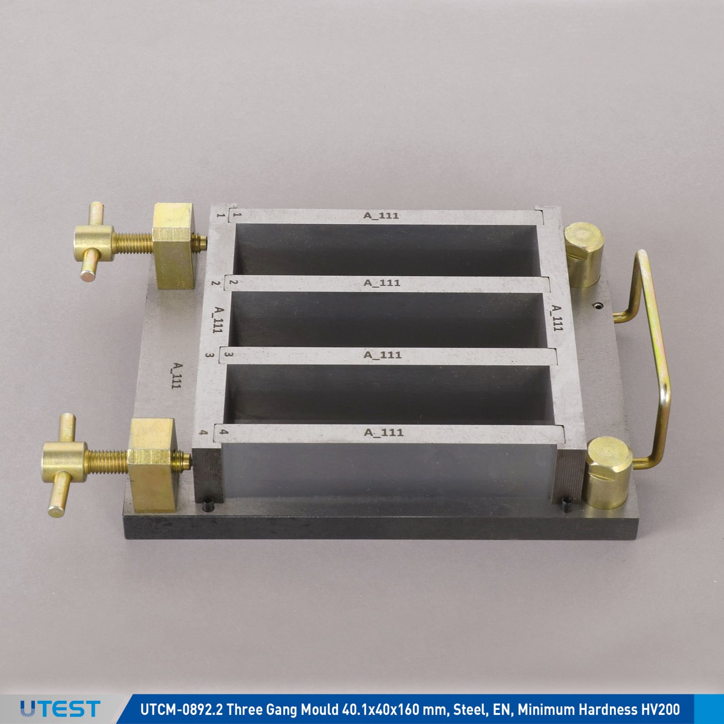
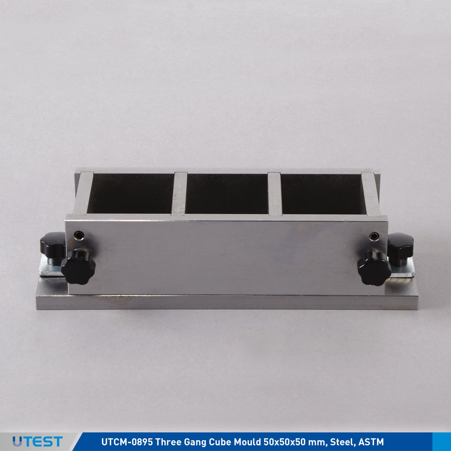
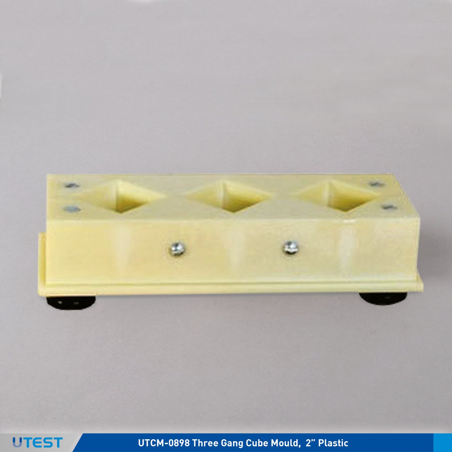
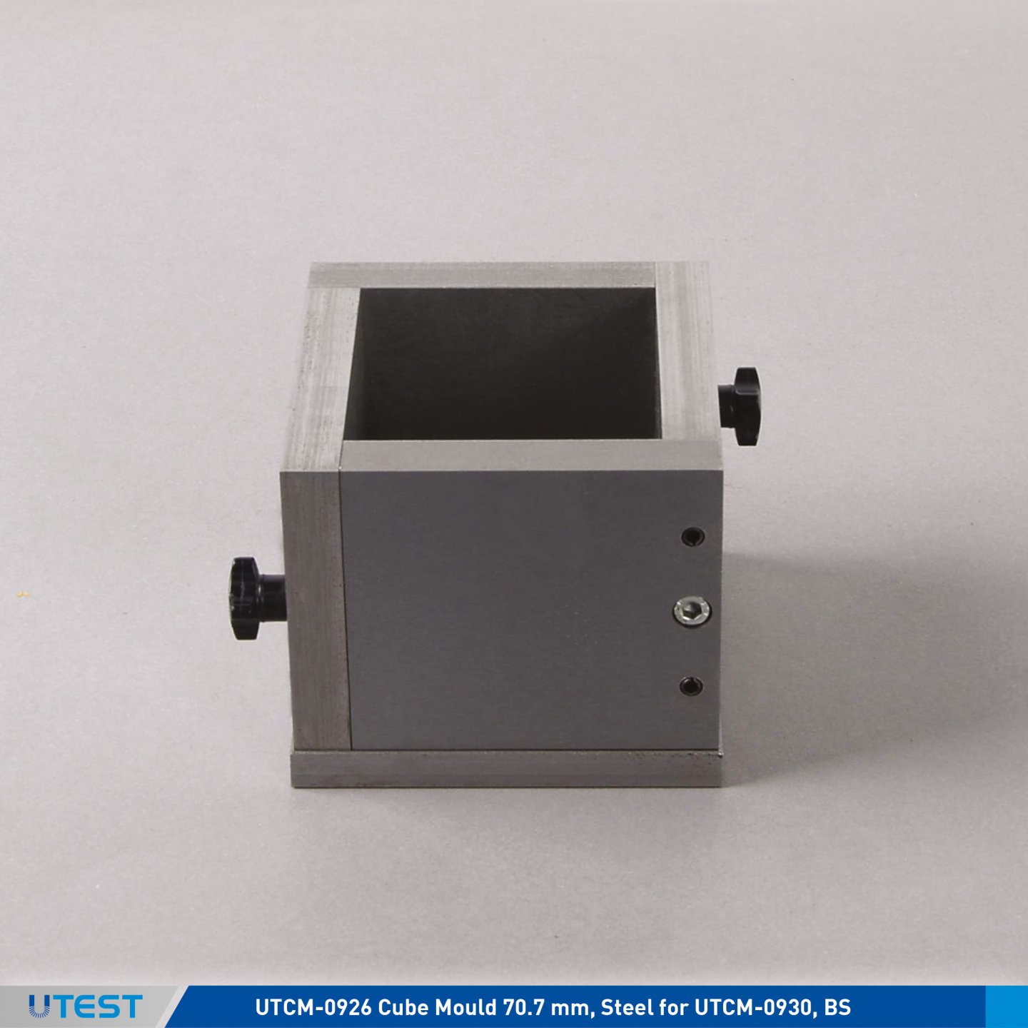
Product Code
|
UTCM-0892.2 |
Three Gang Mould 40.1x40x160 mm, Steel, EN, Minimum Hardness HV200. |
|
UTCM-0892.4 |
Three Gang Mould 40.1x40x160 mm, Steel, EN, Minimum Hardness HV400. |
|
UTCM-0893 |
Feed Hopper for UTCM-0892 |
|
UTCM-0894 |
Short and Long Spreaders and Straightedge for UTCM-0892 |
|
UTCM-0895 |
Three Gang Cube Mould 50x50x50 mm, Steel, ASTM |
|
UTCM-0898 |
Three Gang Cube Mould, 2” Plastic |
|
UTCM-0899A |
Three Gang Mould 40x40x160 mm, Steel, ASTM |
|
UTCM-0926 |
Cube Mould 70.7 mm, Steel, for UTCM-0930, BS |
Standards
EN 196-1, 413-2, 459-2, 1744-1, 1015-10, 1015-11, 13454-2; ASTM C109, C348; BS 4550
All moulds have been manufactured from steel except UTCM-0898 molded using engineered plastic and all internal surfaces are machined.
Minimum surface hardness of UTCM- 0892.4 is HV400 which is recommended by the EN standard. All moulds surfaces are protected with anti-corrosion oil. The webs of UTCM- 0892.4 and UTCM-0899A are matchmarked.
Minimum surface hardness of UTCM-0892.2 is HV200.
|
|
Dimensions |
Weight (approx.) |
|
UTCM-0892.4 |
300x190x70 mm |
10,5 kg (Packed) |
|
UTCM-0893 |
210x200x40 mm |
1 kg |
|
UTCM-0895 |
110x230x60 mm |
3 kg |
|
UTCM-0898 |
110x250x70 mm |
1 kg |
|
UTCM-0899A |
300x190x70 mm |
12 kg (Packed) |
|
UTCM-0926 |
100x125x90 mm |
3,5 kg |
22. Vibrating Machine
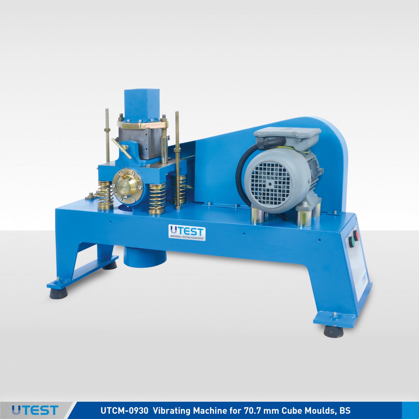
Product Code
|
UTCM-0930 |
Vibrating Machine for 70.7 mm Cube Moulds, BS |
|
UTCM-0926 |
Cube Mould 70.7 mm, BS |
|
Models for 220-240 V 50 Hz, 1ph. |
UTCM-0930-T |
|
Models for 220-240V 60 Hz, 1 ph. |
UTCM-0930-K |
Standards
BS 4550
The UTCM-0930 Vibrating Machine is used for the preparation and compaction of 70.7 mm mortar cube specimens. The mould table is mounted on four springs attached to an eccentric shaft which allows each sample to be vibrated at 12000 cycles per minute. There is a timer on it to preset time and it stops automatically in every 120 seconds.
70.7 mm cube mould (UTCM-0926) should be ordered separately.


UTCM-0926
|
Dimensions |
450x650x850 mm |
|
Weight (approx.) |
80 kg |
|
Eccentric Shaft Rotation |
12000 r.p.m |
|
Power |
1100 W |
23. Curing Cabinet
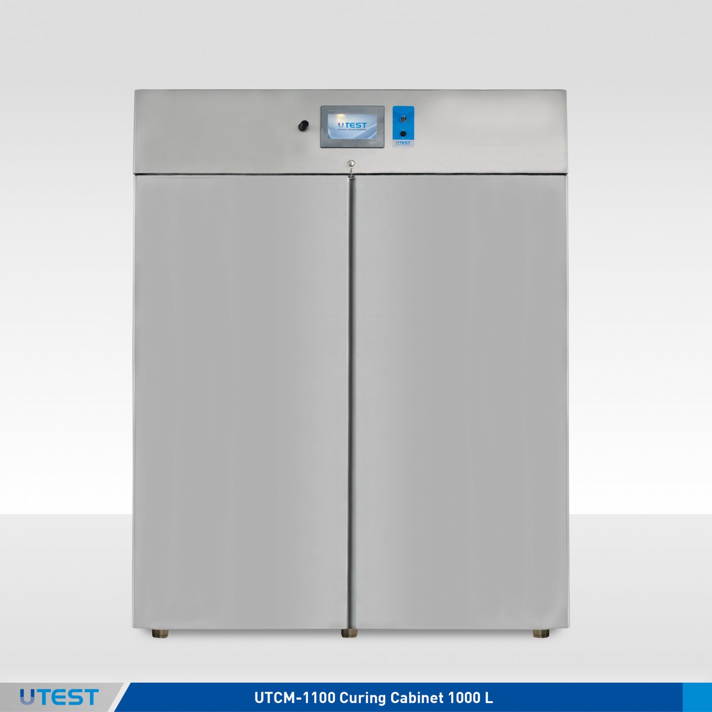
Product Code
|
UTCM-1100 |
Curing Cabinet 1000 L |
|
Models for 220-240 V 50-60 Hz, 1ph. |
UTCM-1100 |
|
Models for 110-120 V 60Hz, 1ph. |
UTCM-1100-N |
Standards
EN 196-1; ISO 679
UTCM-1100 Curing Cabinet, 1000 Liters, for cement based mortar specimens, 20.0 ± 1.0°C temperature and min. 90% Rh and over humidity. The humidity and temperature can be controlled and monitored by a digital unit. Stainless steel interior. 220-240V, 50-60Hz, 1ph.
The humidity and temperature can be controlled and monitored on the digital control unit.
UTCM-1100 Curing Cabinet is also supplied complete with six displaceable shelves.
In order to record temperature, humidity and time data simultaneously, the communication module (UTCU-4940) should be ordered separately.
|
Internal Dimension |
1140x680x1370 mm |
|
External Dimension |
1400x800x2100 mm |
|
Weight (approx.) |
200 kg |
|
Power |
1200 W |
24. Compression and Flexural Frames
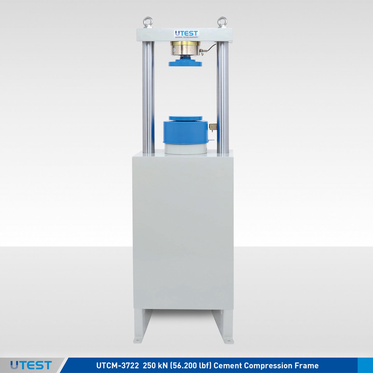
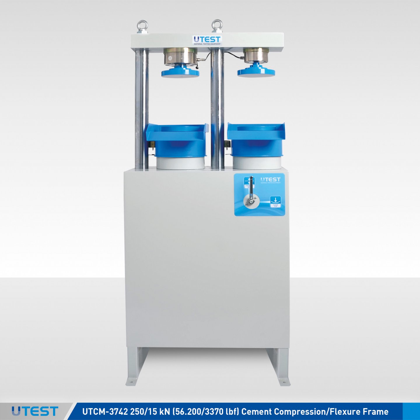
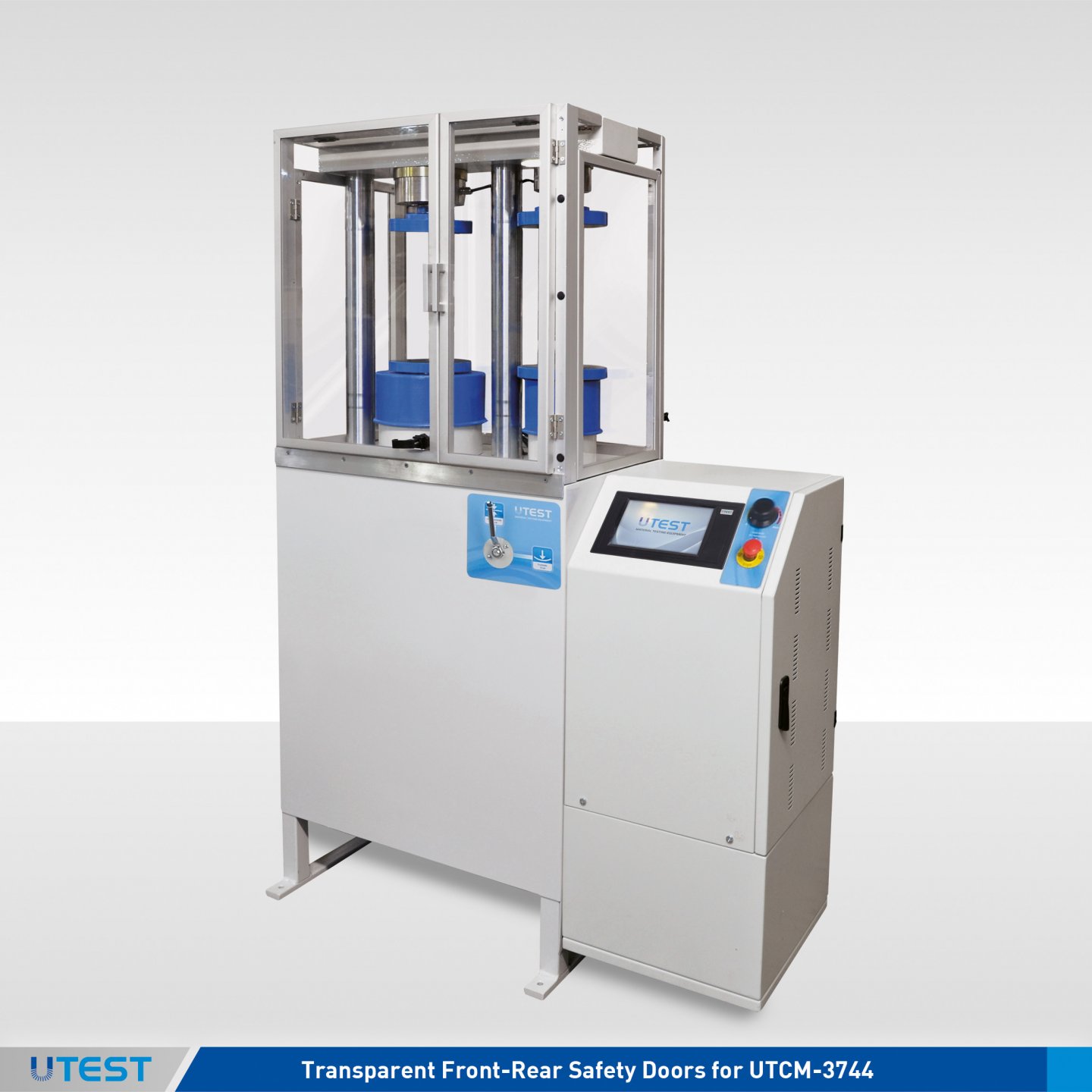
Product Code
|
UTCM-3722 |
250 kN (56.200 lbf) Cement Compression Frame |
|
UTCM-3742 |
250/15 kN (56.200/3370 lbf) Cement Compression/Flexure Frame |
|
UTCM-3724 |
Transparent Front-Rear Safety Doors for UTCM-3722 |
|
UTCM-3744 |
Transparent Front-Rear Safety Doors for UTCM-3742 |
Standards
EN 196-1, 459-2, 1015-11, 13454-2, 13892-2; ASTM C109, C348, C349;BS 4550-3.4
The UTCM-3722 and UTCM-3742, very rigid two column frames have been designed for compression and/or flexure testing of mortar prisms and cubes specimens. Load cells are used on both frames to provide high accuracy in load measuring. Both frames are fitted with round platens with 165 mm diameter and these should be used together with suitable flexure and compression devices.
Distance pieces and transparent front-rear safety doors (should be factory insttalled) should be ordered separately.
Loading Cylinder Assembly & Limit Switch
All frames have a single acting up stroking ram. The diameter of piston changes with regard to the capacity.
The maximum ram stroke is 20 mm, a limit switch is fitted to prevent over travel of the ram which cuts the power to the pump. There is a low friction coaxial bronze seal between the cylinder and the piston fitted to the cylinder.
Dimensions

|
|
UTCM-3722 |
UTCM-3742 |
|
A |
460 mm (18,1”) |
650 mm (25,6”) |
|
B |
300 mm (11,8”) |
266 mm (10,47”) |
|
C |
Ø165 mm (6,5”) |
Ø165 mm (6,5”) |
|
D |
237 mm (9,3”) |
237 mm (9,3”) |
|
E |
500 mm (19,7”) |
500 mm (19,7”) |
|
F |
1580 mm (62,2”) |
1580 mm (62,2”) |
|
Weight |
185 kg (408 lbs) |
280 kg (617 lbs) |
25. Distance Pieces and Platens for Frames for Cement & Mortar

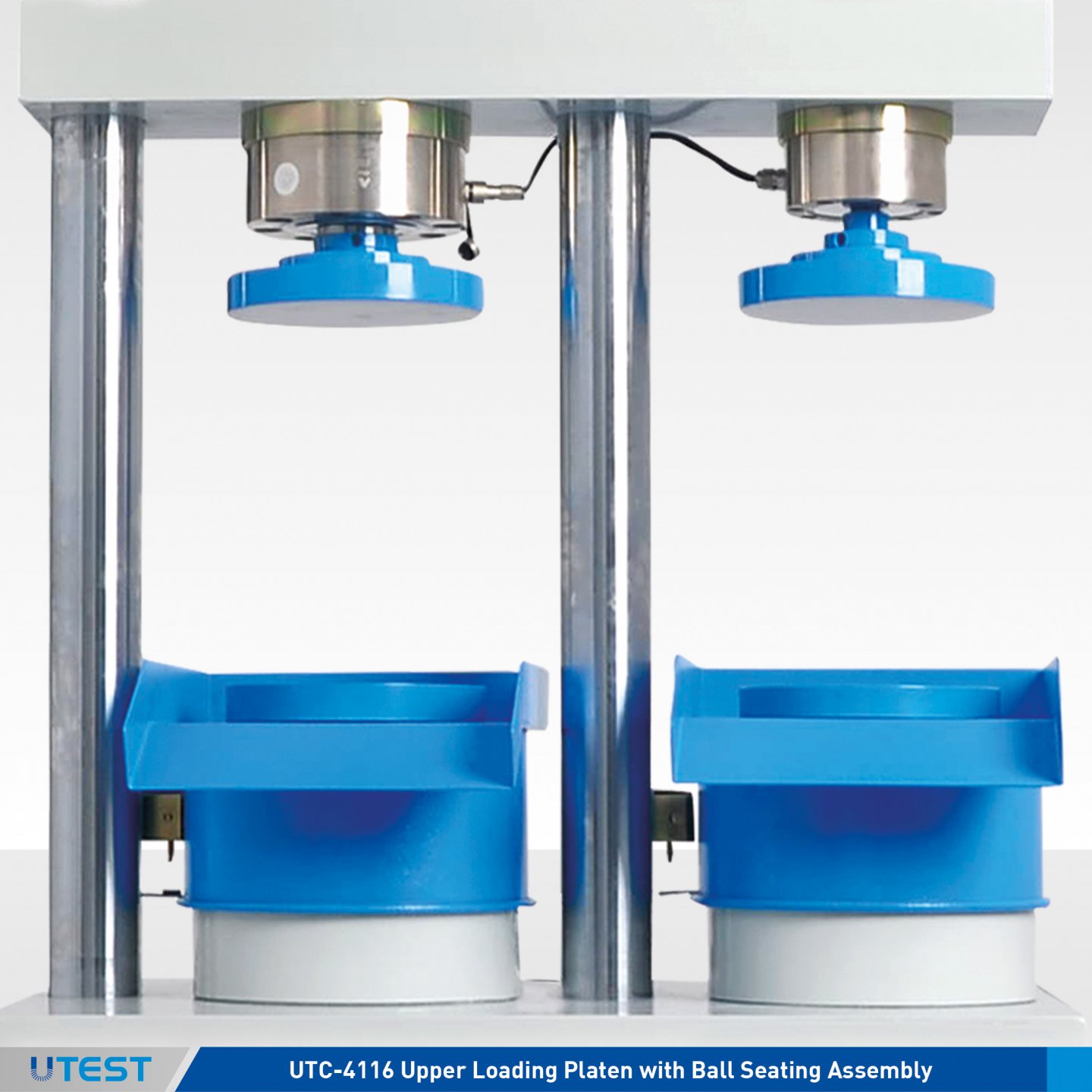
Product Code
|
UTC-4630 |
Distance Piece Ø165mm x 15mm (Ø6,5”x0,59”) |
|
UTC-4631 |
Distance Piece Ø165mm x 30mm (Ø6,5”x1,18”) |
|
UTC-4633 |
Distance Piece Ø165mm x 50mm (Ø6,5”x1,97”) |
|
UTC-4634 |
Distance Piece Ø165mm x 100mm (Ø6,5”x3,93”) |
|
UTCM-4116 |
Lower and Upper Loading Platen with Ball Seating Assembly |
Distance Pieces for Frame
Due to the modular design of the frames any sample with suitable size, load and pace rate can be test on both chambers by decreasing the distance between platens.
Loading Platens
UTCM-4116 Lower and Upper (spherical seated) Loading Platens are manufactured from high quality steel smoothed and finished.
The roughness value for the surface texture of machine and auxiliary platens are 3.2 μm.
26. Hand Operated Hydraulic Power Pack
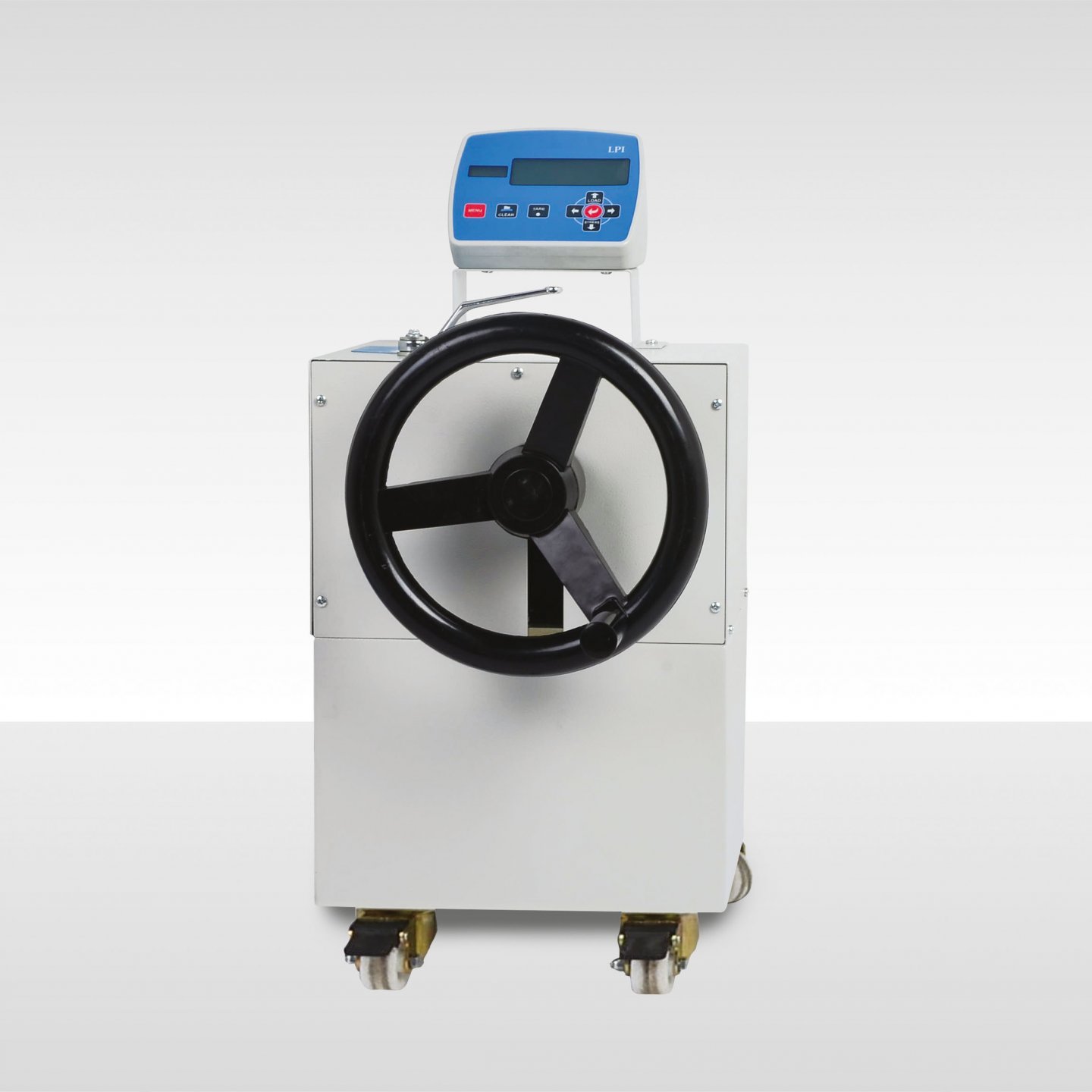

Product Code
|
UTC-4810 |
Hand Operated Hydraulic Power Pack |
|
UTC-4920LP |
LPI Battery Operated Digital Read-Out Unit |
|
UTC-4810MLP |
Hand Operated Hydraulic Power Pack with LPI Battery Operated Digital Read-Out Unit |
The UTC-4810 Hand Operated (Manual) Hydraulic Power Pack has been designed to be used with range of UTEST compression and flexural frames to use on site and/or where electricity is not available.
The pump is equipped with a radial piston pump so that the loading is continuous as long as the user turns the wheel installed on the pump. The loading is uniform as on an automatic machine. The user can easily load up to 400 bars with minimal effort. Maximum working pressure of system is 400 bar.
UTC-4810MLP consists of UTC-4810 and UTC-4920LP. In this application UTC-4920LP is used for reading the applied load by UTC-4810 in any frame.
The specifaications of the LPI Battery Operated Digital Read-Out Unit can be seen on UTC-4920LP page.
|
Dimensions |
300x250x500 mm |
|
Weight (approx.) |
50 kg |
27. Motorized (Semi-Automatic) Hydrolic Power Pack
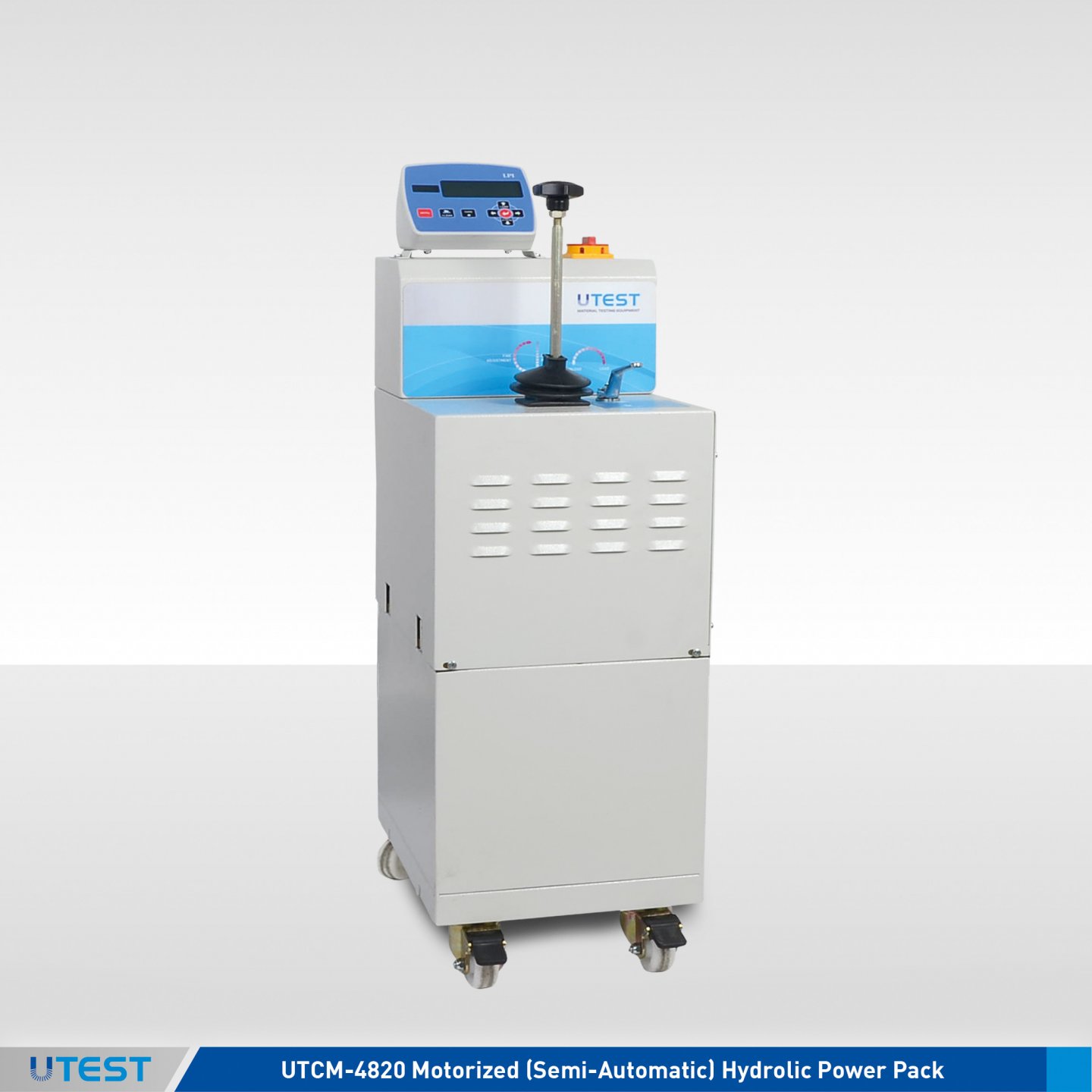
Product Code
|
UTC-4820SLP |
Semiautomatic (Motorized) Hydraulic Power Pack With LPI Battery Operated Digital Readout Unit |
|
UTC-4820 |
Motorized (Semi-Automatic) Hydrolic Power Pack |
|
UTC-4920LP |
LPI Battery Operated Digital Read-Out Unit |
|
Models for 220-240 V 50-60 Hz, 1ph. |
UTC-4820 |
|
Models for 110-120V 60 Hz, 1ph. |
UTC-4820-N |
The UTC-4820SLP Motorized (Semi-Automatic) Power Pack, controlled by a pressure rate control valve is designed to supply the required oil to the load frames for loading. The power pack can load different frames with required pace rates. A rapid approach pump is supplied as standard. The power pack is equipped with a safety valve (maximum pressure valve) to avoid machine overloading. Maximum working pressure of the system is 400 bar.
UTC-4920LP is used with UTC-4820 Motorized (Semi-Automatic) Hydrolic Power Pack for reading the applied load by pressure transducer during the compression tests.Plase see the page of UTC-4920LP “LPI Battery Operated Digital Read-Out Unit” for details of the properties.
If the UTC-4820SLP is supplied stand-alone, it comes with the UTC-4822 (Equipment Set to make UTC-4820 and UTC-4820SLP mobile).
UTC-4820 and UTC-4920LP should be ordered separately for the supply of UTC-4920.SLP.
DUAL STAGE PUMP
- Low pressure gear pump
- High pressure durable variable output pump
On the dual stage pump, a high delivery low pressure gear pump is used for rapid approach, while a low delivery high pressure durable variable output pump is used for test execution. Rapid approach property of the machine shortens the time interval from when the piston starts moving until the upper platen touches the specimen and helps to save a great amount of time in a busy test laboratory.
MOTOR
- Dual pump is driven by an AC motor
- 220 V (110 V), 50-60 Hz single phase and 550 W
DISTRIBUTION BLOCK
- Safety valve (maximum pressure valve)
- Pressure relief valve
A distribution block is used to control the oil flow direction supplied by the dual stage pump which has the safety valve and pressure relief valve mounted upon it.
OIL TANK
The tank (20 L capacity) includes enough oil to fill the mechanism which pushes the ram during the test. The level and oil temperature can be seen on the indicator fitted to the tank. Hydraulic motor oil number 46, must be used.
SAFETY FEATURES
- Maximum pressure valves to avoid machine overloading
|
Dimensions |
300x420x850 mm |
|
Weight (approx.) |
70 kg |
|
Power |
550 W |
28. Automatic Hydraulic Power Pack with U-Touch PRO Control Unit
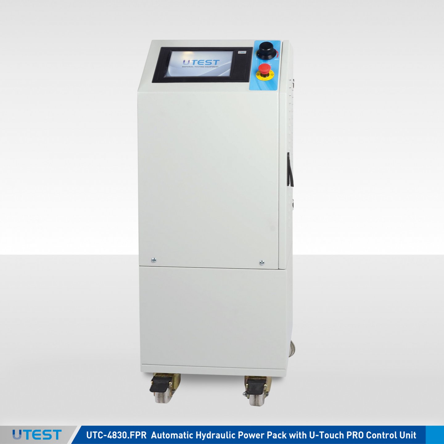
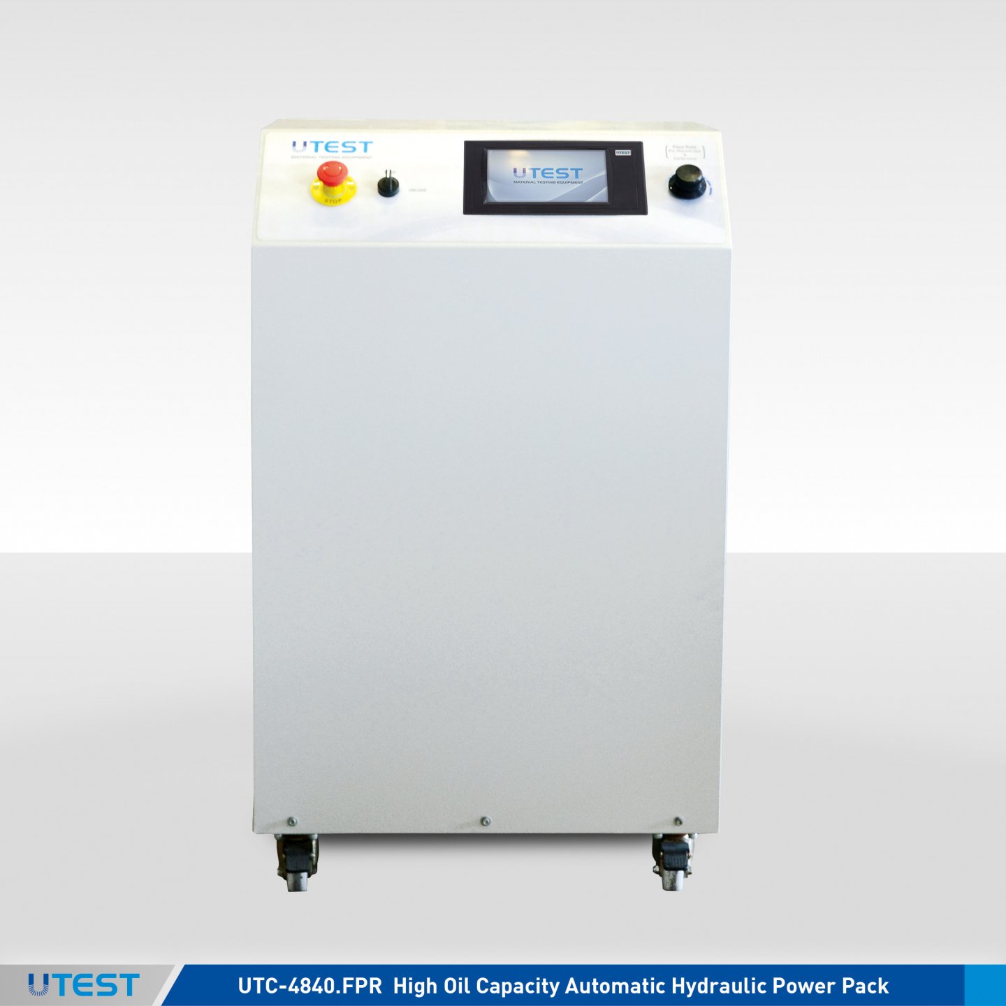
Product Code
|
UTC-4830.FPR |
Automatic Hydraulic Power Pack with U-Touch PRO Control Unit |
|
UTC-4840.FPR |
High Oil Capacity Automatic Hydraulic Power Pack with U-Touch PRO Control Unit for the Frames with Double Ended Pistons |
|
UTC-4841.FPR |
High Oil Capacity Automatic Hydraulic Power Pack with U-Touch PRO Control Unit for the Frames with Single Ended Pistons |
|
Models for 220-240V 50-60 Hz, 1ph. |
UTC-4830.FPR |
UTC-4840.FPR |
UTC-4841.FPR |
|
Models for 110-120V 60 Hz, 1ph. |
UTC-4830.FPR-N |
UTC-4840.FPR-N |
UTC-4841.FPR-N |
The UTC-4830FPR Automatic Hydraulic Power Pack, dual stage, controlled by U-Touch PRO Control Unit is designed to supply the required oil to the load frames for loading. The power pack is very silent, even at full load A rapid approach pump is supplied as standard. A safety valve (maximum pressure valve) is used to avoid machine overloading.
The UTC-4840FPR and UTC-4841FPR have the same specifications with UTC-4830FPR except for high oil capacity. As the name suggests, UTC-4840FPR is used with the frames with double ended pistons and UTC-4841FPR is used with the frames with single ended pistons.
If the UTC-4830.FPR or UTC-4840.FPR or UTC-4841.FPR is supplied stand-alone, it comes with the UTC-4832 (Equipment Set to make UTC-4820 and UTC-4820SLP mobile).

DUAL STAGE PUMP
- Low pressure gear pump
- High pressure durable variable output pump
On the dual stage pump, a high delivery low pressure gear pump is used for rapid approach, while low delivery high pressure radial piston pump is used for test execution. Rapid approach facility of the machine shortens the time interval from when the piston starts moving until the upper platen touches to the specimen, this facility saves a great amount of time in a busy test laboratory.
MOTOR
The motor which drives the dual pump is a 0.75 kW AC motor which is controlled by an Omron J7 motor inverter. The variation in the oil flow is executed with the variation of the rotation speed of the motor.
DISTRIBUTION BLOCK
Distribution block is used to control the oil flow direction supplied by the dual stage pump and the following hydraulic components are fitted to it:
a - Solenoid valve
b - Safety valve (maximum pressure valve)
c - Transducer
d - Low pressure gear pump
e - High pressure radial piston pump
OIL TANK
The tank includes enough oil to fill the mechanism which pushes the ram during the test. The level and oil temperature can be seen on the indicator fitted to the tank. The oil capacity of the tank is 20 lt. for UTC-4830FPR and and 32 lt. for UTC-4840 FPR. Hydraulic motor oil, number 46, must be used.
PLEASE see the pages of “U-Touch PRO Control Unit UTC-4930.FPR” for details of the properties.


UTC-4830FPR UTC-4840FPR
|
|
UTC-4830FPR |
UTC-4840FPR |
|
Dimensions |
370x400x920 mm |
605x455x1015 mm |
|
Weight (approx.) |
85 kg |
150 kg |
|
Power |
1000 W |
1000 W |
29. MANUEL Cement Compression & Flexure Testing Machines
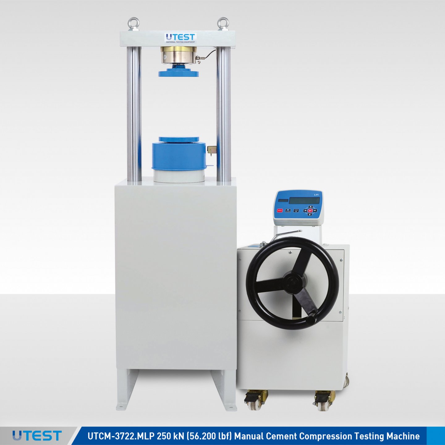
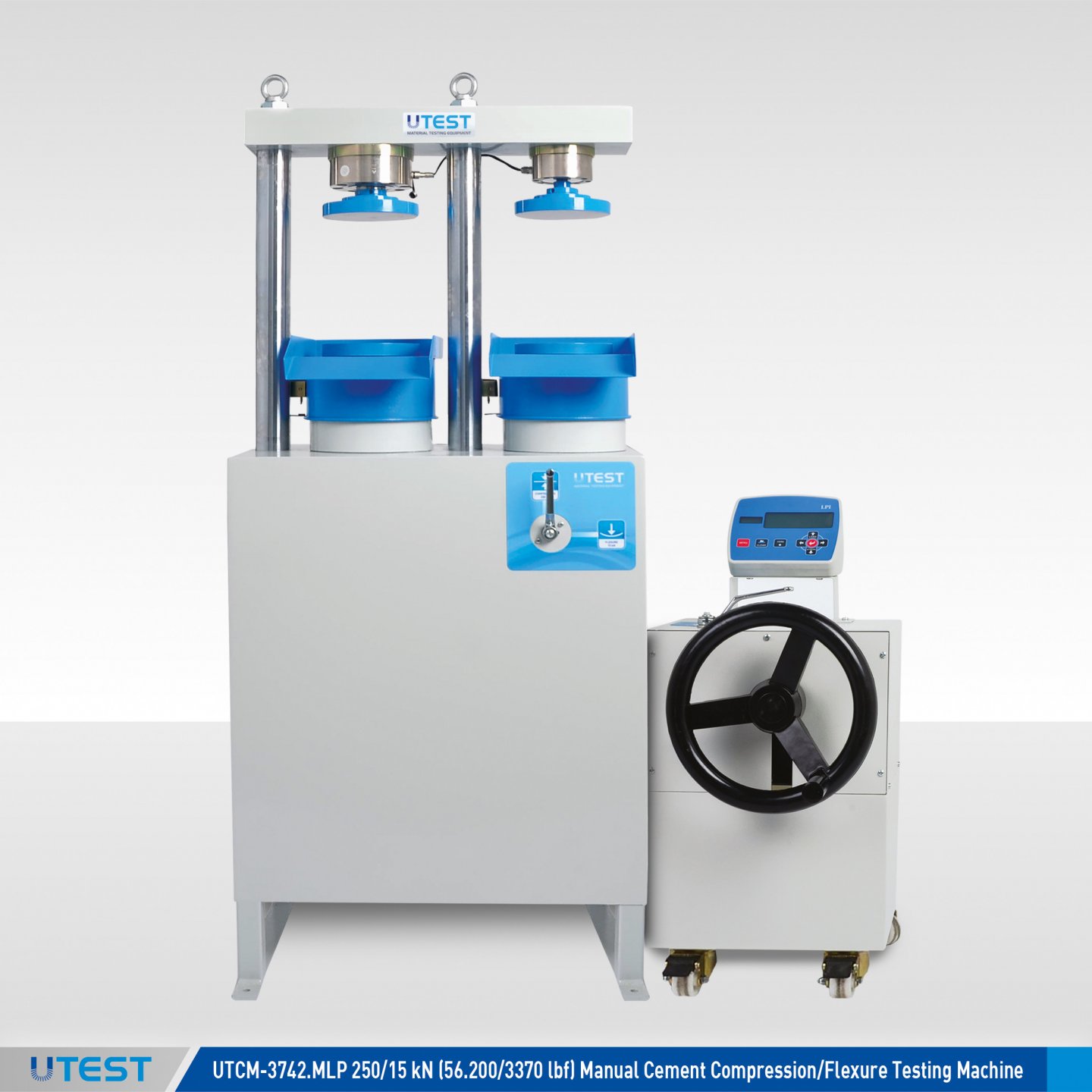
Product Code
|
UTCM-3722.MLP |
250 kN (56.200 lbf) Manual Cement Compression Testing Machine |
|
UTCM-3742.MLP |
250/15 kN (56.200/3370 lbf) Manual Cement Compression/Flexure Testing Machine |
|
UTCM-4200A |
Flexure Jig Assembly to test 40x40x160 mm prisms, ASTM |
|
UTCM-4200E |
Flexure Jig Assembly to test 40.1x40x160 mm prisms, EN |
|
UTCM-4210A |
Compression Jig Assembly to test 50 mm (2”) cubes |
|
UTCM-4210E |
Compression Jig Assembly to test portions of 40.1x40x160 mm prisms, EN |
|
UTCM-4210B |
Compression Jig Assembly BS, to test 70,7 mm cubes |
|
UTCM-3724 |
Transparent Front-Rear Safety Doors for UTCM-3722 |
|
UTCM-3744 |
Transparent Front-Rear Safety Doors for UTCM-3722 |
Standards
EN 196-1, 459-2, 1015-11, 13454-2, 13892-2; ASTM C109, C348, C349; BS 4550-3.4
The UTCM-3722.MLP and UTCM-3742.MLP single and double testing chamber Manual compression and flexure testing machines are designed to perform reliable strength and flexure tests on mortar specimens. The manual machines are especially suitable for on-site applications when electric power supply is not available.
Being a low cost alternative, UTEST manual testing series combine precision and simplicity with the unique design of the manual power pack which enables even an inexperienced operator to perform excellent compression and flexure tests on-site.
These manual testing machines conform to the standards EN 196-1, 459-2, 1015-11, 13454-2; ASTM C 109, C348, C349 by using suitable accessories. They also meet with the requirements of CE norms with respect to operator health and safety.
The UTEST manuel cement compression and flexure testing machines consist of very rigid two column single or double chamber frame, manuel power pack and data acquisition system LPI.
Compression and flexture jigs, distance pieces, and also removable transparent front-rear safety doors (should be factory installed) should be ordered separately.

Manuel Power Pack
The Hand Operated (Manual) Hydraulic Power Pack has been designed to be used with range of UTEST Compression machines and flexural frames to use on site and/or where electricity is not available.
The pump is equipped with a radial piston pump so that the loading is continuous as long as user turns the wheel installed on the pump. The loading is uniform as on an automatic machine.

LPI Battery Operated Digital Readout Unit
The LPI Battery Operated Digital Readout Unit (UTC-4920LP) has been designed to use with load cells or pressure transducers on different material test applications.
The unit is operates with DC voltage source of -1,5 to 1,5 volts.
- Real time numeric display of load and load rate
- 1 channel with two different calibration table (by changing the sensor belong to other frame, the unit can be control for second test frame)
- Peak hold property
- Multi-point calibration
- Can operate with 2 x AA batteries
- Easy preload zeroing
- Serial port for PC or printer
- 8 keys keyboard
Technical Specifications
|
Model |
UTCM-3722 |
UTCM-3742 |
|
|
Test Type |
Compression |
Flexure |
Compression |
|
Capacity |
250 kN (56.200 lbf) |
15 kN (3370 lbf) |
250 kN(56.200 lbf) |
|
Class 1 Measuring Range |
1 % for 250 kN |
1 % for 15 kN |
1 % for 50 kN |
|
The Roughness Value for Texture of Loading Platens |
≤3.2 μm |
≤3.2 μm |
≤3.2 μm |
|
Lower Platen Dimensions |
165 mm (6,5”) |
165 mm (6,5”) |
165 mm (6,5”) |
|
Upper (spherical seated) Platen Dimensions |
165 mm (6,5”) |
165 mm (6,5”) |
165 mm (6,5”) |
|
Maximum Vertical Clearance Between Platens |
237 mm (9,3”) |
237 mm (9,3”) |
237 mm (9,3”) |
|
Piston Diameter |
Ø160 mm (6,3”) |
Ø160 mm (6,3”) |
Ø160 mm (6,3”) |
|
Maximum Piston Movement with Limit Switch |
20 mm (1,18”) |
20 mm (1,18”) |
20 mm (1,18”) |
|
Horizontal Clearance |
300 mm (11,8”) |
274 mm (10,8”) |
266 mm (10,47”) |
|
Oil Capacity |
13 L |
13 L |
|
|
Rapid Approach Rate |
50 mm/min 2 inc/min |
80 mm/min 3,15 inc/min |
50 mm/min 2 inc /min |
|
Dimensions (WxLxH) |
760x500x1580 mm (30”x19,7”x62,2”) |
950x500x1580 mm ( 37,4”x19,7”x62,2”) |
|
|
Weight |
230 kg (518 lbs) |
320 kg (705 lbs) |
|
The Maximum horizontal clearance for placing the sample is limited by the border of the platens. Sample must be placed such that its ends will not overlap the ends of platens and it must be centered perfectly.The minimum vertical clearance for the specimen can be adjusted using the distance pieces.
30. SEMI-AUTOMATIC (Motorized) Cement Compression & Flexure Testing Machines
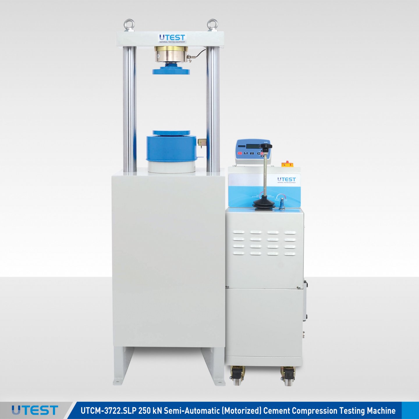
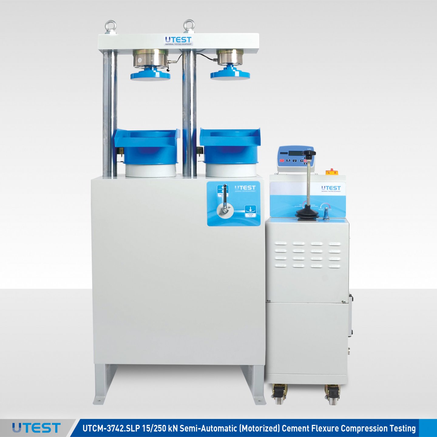
Product Code
|
UTCM-3722.SLP |
250 kN (56.200 lbf) Semi-Automatic (Motorized) Cement Compression Testing Machine |
|
UTCM-3742.SLP |
15/250 kN ( 56.200/3370 lbf) Semi-Automatic (Motorized) Cement Flexure Compression Testing |
|
UTCM-4200E |
Flexure Jig Assembly to test 40,1x40x160 mm prisms, EN |
|
UTCM-4200A |
Flexure Jig Assembly to test 40x40x160 mm prisms, ASTM |
|
UTCM-4210E |
Compression Jig Assembly to test portions of 40.1x40x160 mm prisms, EN |
|
UTCM-4210A |
Compression Jig Assembly to test 50 mm (2”) cubes |
|
UTCM-4210B |
Compression Jig Assembly BS, to test 70,7 mm cubes |
|
UTCM-3724 |
Transparent Front-Rear Safety Doors for UTCM-3722 |
|
UTCM-3744 |
Transparent Front-Rear Safety Doors for UTCM-3742 |
|
Models for 220-240V 50-60 Hz, 1ph. |
UTCM-3722.SLP |
UTCM-3742.SLP |
|
Models for 110-120V 60 Hz, 1ph. |
UTCM-3722.SLP-N |
UTCM-3742.SLP-N |
Standards
EN 196-1, 459-2, 1015-11, 13454-2, 13892-2; ASTM C109, C348, C349; BS 4550-3.4
The UTEST Semi-Automatic (Motorized) range of single testing chamber and double testing chamber compression and flexure testing machines have been designed for reliable and consistent testing of mortar samples. These compression and flexure testers are the results of continuous applications and research studies to upgrade the machines with the latest technologies and conform with current standards EN 196-1, 459-2, 1015-11, 13454-2; ASTM C 109, C348, C349 and BS 3892-1, 4551-1 in terms of its technical properties taking into account client requirements by using suitable accessories. These testers also meet the requirements of CE norms for safety and health of the operator.
The UTEST Semi-Automatic cement compression and flexure testing machines allow operators who have minimal experience to perform the tests.
The UTEST Semi-Automatic cement compression and flexure testing machines consist of a very rigid two column single or double chamber frame and UTC-4820SLP hydraulic powerpack with LPI Battery Operated Digital Readout Unit.
Compression and flexure jigs, distance pieces, and also removable transparent front-rear safety doors (should be factory installed) should be ordered separately.

Power Pack
The Power Pack of the Semi-Automatic (Motorized) Cement Compression Testing Machine controlled by a pressure rate control valve, is designed to supply the required oil to the load frames for loading. The power pack can load different frames with required pace rates. A rapid approach pump is supplied as standard. The power pack is equipped with a safety valve (maximum pressure valve) to avoid machine overloading.
The dual stage pump is formed by two groups, one is low pressure gear pump and second high pressure radial piston pump.
On the dual stage pump, high delivery low pressure gear pump is used for rapid approach, while low delivery high pressure durable variable output pump is used for test execution. Rapid approach property of the machine shortens the time interval from the piston starts moving until the upper platen touches to the specimen and helps to save a great amount of time in case of numerous specimens are going to be tested.
The motor which drives the dual pump is an AC motor and 0.55 kW.
A distribution block is used to control the oil flow direction supplied by the dual stage pump and those are are fitted to solenoid valve, safety valve (maximum pressure valve), low pressure gear pump and high pressure radial piston pump
The tank (20 L capacity) includes enough oil to fill the mechanism which pushes the ram during the test. The level and oil temperature can be seen on the indicator fitted to the tank. Hydraulic motor oil number 46, must be used in the tank.
LPI Battery Operated Digital Readout Unit
The LPI Battery Operated Digital Readout Unit (UTC-4920LP) has been designed to use with load cells or pressure transducers on different material test applications.
The unit is operates with DC voltage source of -1,5 to 1,5 volts.
- Real time numeric display of load and load rate
- 1 channel with two different calibration table (by changing the sensor belong to other frame, the unit can be control for second test frame)
- Peak hold property
- Multi-point calibration
- Can operate with 2 x AA batteries
- Easy preload zeroing
- Serial port for PC or printer
- 8 keys keyboard
Main Features
- Class A (ASTM) starting from with the 1 % of the 250 kN and 15 kN capacity Multi-point calibration
- Multi-point calibration
- 2 channels for load-cell or pressure transducer with two different calibration table (LPI Battery Operated Digital Readout Unit (UTC-4920LP)
- Real time numeric display of load and load pressure
- Peak hold property
- RS232 Serial port for PC or thermal or dot matrix printer
- Free of charge Utest software for compression/flexture testing machines(USOFT-4820.SLP) for compression, flexture, splitting tensile strength tests of construction materials such as concrete, cement, brick/masonary units
Safety Features
- Maximum pressure valves to avoid machine overloading
- Piston travel limit switch
- Removable transparent front-rear safety doors (Should be factory installed and ordered separately)
Utest Software for Semi-Automatic Cement Compression/Flexure Tests (USOFT-3722.SLP)
USOFT-3722.SLP Test Software is improved for semi-automatic cement compression and flexural testing machineswith LPI Battery Operated Digital Readout Unit durring the test to collect and record data and to prepare the report containing the results obtained.Before the test, a PC which the Utest software is installed is connected to RS232 port of LPI reading unit, the data obtained in the test can be monitored and recorded in real time. The advanced functions for data base management provide an easy navigation of all saved data. Test report including the test results and user defined test information (names and the Company details, test type, specimen type, user info and other knowledge required) can be print out.
Technical Specifications
|
Model |
UTCM-3722.SLP |
UTCM-3742.SLP |
|
|
Test Type |
Compression |
Flexure |
Compression |
|
Capacity |
250 kN (56.200 lbf) |
15 kN (3370 lbf) |
250 kN (56.200 lbf) |
|
Class 1 Measuring Range |
1 % for 250 kN |
1 % for 15 kN |
1 % for 50 kN |
|
The Roughness Value for Texture of Loading Platens |
≤ 3.2 µm |
≤ 3.2 µm |
≤ 3.2 µm |
|
Lower Platen Dimensions |
Ø165 mm (6,5”) |
Ø165 mm (6,5”) |
Ø165 mm (6,5”) |
|
Upper Platen Dimensions |
Ø165 mm (6,5”) |
Ø165 mm (6,5”) |
Ø165 mm (6,5”) |
|
Maximum Vertical Clearance Between Platens |
237 mm (9,3”) |
237 mm (9,3”) |
237 mm (9,3”) |
|
Piston Diameter |
Ø160 mm (6,3”) |
Ø160 mm (6,3”) |
Ø160 mm (6,3”) |
|
Maximum Piston Movement with Limit Switch |
20 mm (1,18”) |
20 mm (1,18”) |
20 mm (1,18”) |
|
Horizontal Clearance |
300 mm (11,8”) |
274 mm (10,8”) |
266 mm (10,47”) |
|
Power |
550 W |
550 W |
|
|
Oil Capacity |
20 L (0,7 ft3) |
20 L (0,7 ft3) |
|
|
Maximum Working Pressure |
125 bar |
30 - 125 bar |
|
|
Rapid Approach Rate |
50 mm/min 2 inc/min |
80 mm/min 3,15 icn/min |
50 mm/min 2 inc /min |
|
Dimensions (WxLxH) |
760x500x1580 mm (30”x19,7”x62,2”) |
950x500x1580 mm ( 37,4”x19,7”x62,2”) |
|
|
Weight |
255 kg (562 lbs) |
350 kg (772 lbs) |
|
The Maximum horizontal clearance for placing the sample is limited by the border of the platens. Sample must be placed such that its ends will not overlap the ends of platens and it must be centered perfectly. The suitable vertical clearance for the specimen can be adjusted using the distance pieces.
31. AUTOMATIC Cement Compression & Flexure Testing Machines
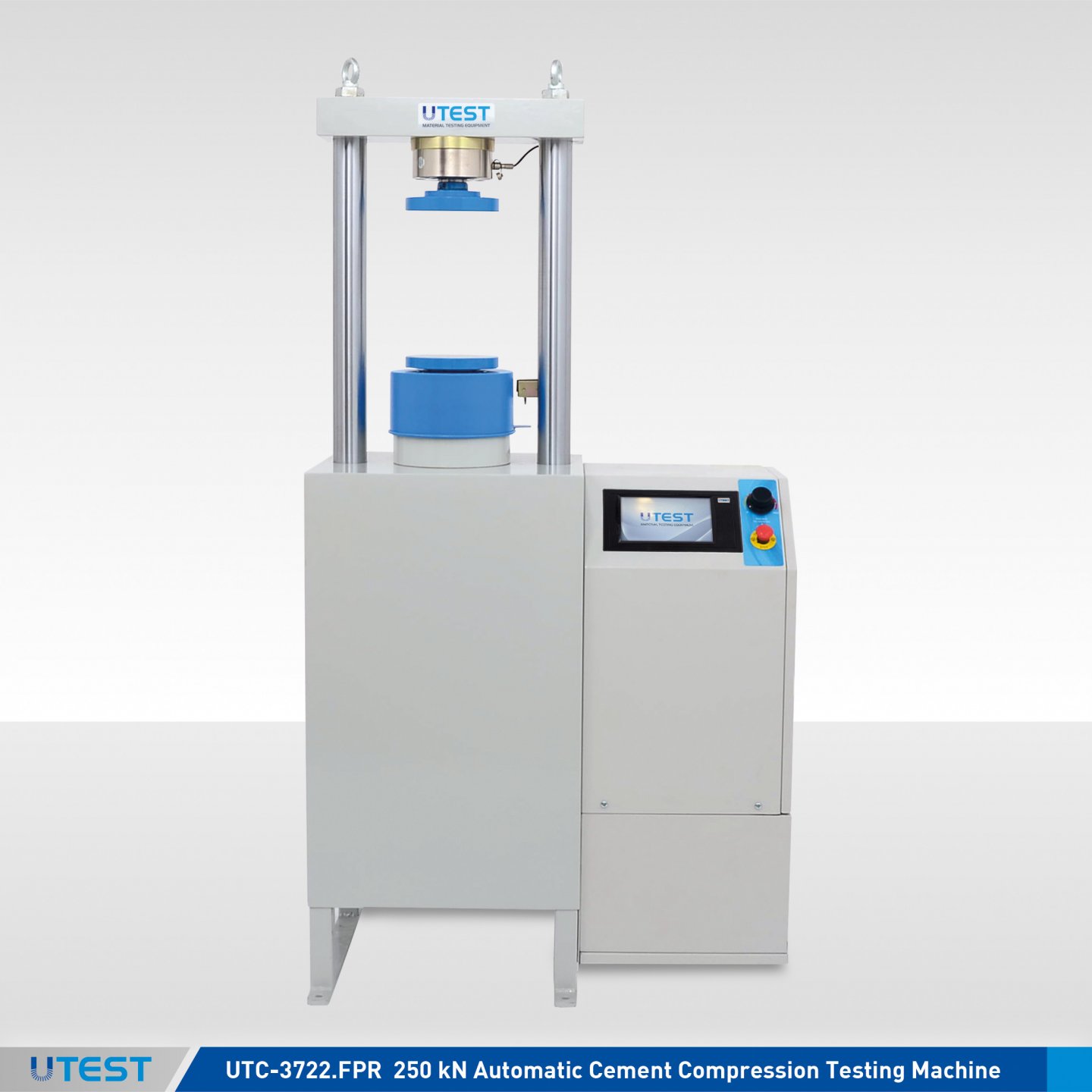


Product Code
|
UTCM-3722.FPR |
250 kN (56.200 lbf) Automatic Cement Compression Testing Machine |
|
UTCM-3742.FPR |
15/250 kN ( 56.200/3370 lbf) Automatic Cement Flexure/Compression Testing Machine |
|
UTCM-4200A |
Flexure Jig Assembly to test 40x40x160 mm prisms, ASTM |
|
UTCM-4200E |
Flexure Jig Assembly to test 40.1x40x160 mm prisms, EN |
|
UTCM-4210A |
Compression Jig Assembly to test 50 mm (2”) cubes |
|
UTCM-4210E |
Compression Jig Assembly to test portions of 40.1x40x160 mm prisms, EN |
|
UTCM-4210B |
Compression Jig Assembly BS, to test 70,7 mm cubes |
|
UTCM-3724 |
Transparent Front-Rear Safety Doors for UTCM-3722 |
|
UTCM-3744 |
Transparent Front-Rear Safety Doors for UTCM-3742 |
|
Models for 220-240 V 50-60 Hz, 1ph. |
UTCM-3722.FPR |
UTCM-3742 FPR |
|
Models for 110-120 V 60Hz, 1ph. |
UTCM-3722.FPR-N |
UTCM-3742.FPR-N |
Standards
EN 196-1, 459-2, 1015-11, 13454-2, 13892-2; ASTM C109, C348, C349; BS 4550-3.4
The UTEST Automatic range of single testing chamber and double testing chamber compression and flexure testing machines have been designed for reliable and consistent testing of mortar samples. These compression and flexure testers are the results of continuous applications and research studies to upgrade the machines with the latest technologies and conform the current standards EN 196-1, 459-2, 1015-11, 13454- 2; ASTM C 109, C348, C349 in terms of its technical properties taking into account client requirements by using suitable accessories. These machines also meet the requirements of CE norms for safety and health of the operator.
Tests can be performed by either on UTC-4930.FPR U-Touch Control Unit or on a computer with using USOFT-4830.FPR Software which is provided free of charge with the machines. The advantages of performing tests on computer with using UTEST Software, such as reporting, graphical output, etc. can be seen in detail at the USOFT-4830.FPR pages. (The UTEST Software for Automatic Compression / Flexure Testing Machines with UTC-4830FPR Hydrolic Power Pack)
Compression and flexture jigs, distance pieces, and also removable transparent front-rear safety doors (should be factory installed) should be ordered separately.
The UTEST automatic cement compression and flexure testing machines allow less experienced operators to perform the tests. Once the machine has been switched on and the specimen is positioned and centered by the help of centering apparatus. The only required operations are;
- Setting test parameters, including pace rate (only required when the specimen type is changed.)
- Choosing the compression or flexure frame by using the changeover valve.
- Pressing the START button on the control unit.
- The machine automatically starts the rapid approach; switches the test speed after 1% of the load capacity of the machine and stops once the specimen failure.
- Automatically saves the test parameters and test results.
The UTEST automatic cement compression and flexure testing machines consist of very rigid two column single or double chamber frames (see table) and an automatic hydraulic power pack with U-Touch Control Unit
Main Features
- Pace rate control from 50 N/sec (flexture) to 2,4 kN/sec (compression)
- Load measurement accuracy Class 1 acc.to EN ISO 7500-1) and Class A acc to ASTM E74 starting from with the 1 %. for 250 kN and 15 kN capacity
- Supplied with factory calibration certificate for load measurement
- Closed loop control with automatic test procedure.
- Can make the test with load control
- Stand-Alone control or computer control
- Free of charge Utest software(USOFT-4830.FPR) for the tests
- Load measurment with the load cell.
- Hydrolic pump with dual stage for rapid approach
- Piston return at the end of test automatically
- Adjustable rapid approach rate
U-Touch Control Unit for Automatic Compression/Flexure Testing Machines
U-Touch Control Unit UTC-4930.FPR is designed to perform automatically compression, flexure and splitting tensile strength tests of construction materials such as cement mortar, concrete, masonary units/blocks by controlling the Utest automatic compression / flexure testing machines.
All the operations of U-Touch are controlled from the front panel touch screen display.
U-Touch Control Unit has easy to use menu options. It displays all menu option listings simultaneously, allowing the operator to access the required option in a seemless manner to activate the option or enter a numeric value to set the test parameters. Digital graphic display is able to draw real-time "Load vs. Time", or "Stress vs. Time" graphics
PLEASE see the pages of “U-Touch Control Unit for Automatic Compression/Flexure Testing Machines” for details of the properties.
UTEST Software for Automatic Compression / Flexure Testing Machines
UTEST software USOFT-4830.FPR provides to perform automatically compression, flexure and splitting tensile strength tests of construction materials such as concrete, cement mortar, masonary units/blocks by controlling the Utest automatic compression / flexure testing machines.
The advantages of performing tests on computer with using UTEST Software, such as reporting, graphical output, etc. can be seen in detail at the pages of UTEST Software for Automatic Compression / Flexure Testing Machines.
Safety Features
- Maximum pressure valves to avoid machine overloading
- Piston travel limit switch
- Emergency stop button
- Software controlled maximum load value
- Removable transparent front-rear safety doors (Should be factory installed and ordered separately)
Technical Specifications
|
Model |
UTCM-3722.FPR |
UTCM-3742.FPR |
|
|
Test Type |
Compression |
Flexure |
Compression |
|
Capacity |
250 kN (56.200 lbf) |
15 kN (3370 lbf) |
250 kN (56.200 lbf) |
|
The Roughness Value for Texture of Loading Platens |
≤3.2 μm |
≤3.2 μm |
≤3.2 μm |
|
Lower Platen Dimensions |
Ø165 mm (6,5”) |
Ø165 mm (6,5”) |
Ø165 mm (6,5”) |
|
Upper Platen Dimensions |
Ø165 mm (6,5”) |
Ø165 mm (6,5”) |
Ø165 mm (6,5”) |
|
Maximum Vertical Clearance Between Platens |
237 mm (9,3”) |
237 mm (9,3”) |
237 mm (9,3”) |
|
Piston Diameter |
Ø160 mm (6,3”) |
Ø160 mm (6,3”) |
Ø160 mm (6,3”) |
|
Maximum Piston Movement |
20 mm (1,18”) |
20 mm (1,18”) |
20 mm (1,18”) |
|
Horizontal Clearance |
300 mm (11,8”) |
274 mm (10,8”) |
266 mm (10,47”) |
|
Power |
750 W |
750 W |
|
|
Oil Capacity |
20 L (0,7 ft3) |
20 L (0,7 ft3) |
|
|
Maximum Working Pressure |
125 bar |
30 - 125 bar |
|
|
Rapid Approach Rate |
50 mm/min 2 inc/min |
80 mm/min 3,15 icn/min |
50 mm/min 2 inc /min |
|
Dimensions (WxLxH) |
830x500x1580 mm (32,7”x19,7”x62,2”) |
1020x500x1580 mm (40,2”x19,7”x62,2”) |
|
|
Weight |
270 kg (595 lbs) |
365 kg (805 lb) |
|
32. U-Touch PRO Control Unit for Automatic Compression/Flexure Testing Machines
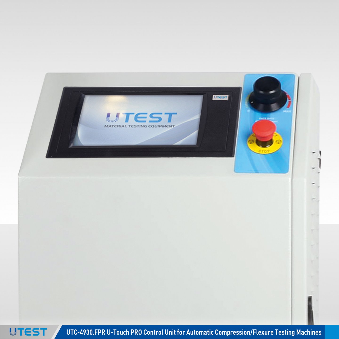
Product Code
|
UTC-4930.FPR |
U-Touch PRO Control Unit for Automatic Concrete&Cement Compression/Flexure Testing Machines 110-220V 50-60 Hz. 1 ph |
UTC-4930.FPR U-Touch PRO Control Unit,for Automatic Concrete&Cement Compression/Flexure Testing Machines designed to control the automatic compression/flexure testing machines for compression, flexure, splitting tensile strength tests of construction materials such as concrete, cement mortar, masonary units/blocks.
All the operations of UTC-4930.FPR Control Unit are controlled from the front panel color resistive touch screen display and function keys. The unit can be configured as using for two frames or one frame with three dispalacement transducers.
The Control Unit has easy to use menu options. It displays all menu option listings simultaneously, allowing the operator to access the required option in a seemless manner to activate the option or enter a numeric value to set the test parameters. Its specimen setting sub-menu lists different specimen types including but not limited to cube, cylinder, block, beam, beam double upper bearers, cube splitting tensile, cylinder splitting tensile, paving block splitting tensile and kerb flexure. Digital graphic display of the unit is able to draw real-time "Load vs. Time" or "Stress vs. Time" graphics.
UTC-4930.FPR Unit offers many addition unique features.Thanks to its built-in internet protocol suite, every aspect of the device can be controlled remotely from anywhere around the world.
Following tests can be perform by on UTC-4930.FPR control unit ( also with appropriate hydraulic power pack, testing frame and accessories);
- Compressive Strength of Concrete Cylinders / Cubes
- Flexural Strength of Concrete Beams
- Flexural Strength of Concrete Kerbs
- Tensile Splitting Strength of Concrete Cylinders / Cubes
- Tensile Splitting Strength of Concrete Paving Blocks
- Compressive Strength of Masonry Units/Blocks
- Flexural Strength of Concrete Flagstones/Slabs
- Compressive Strength of Hydraulic-Cement Mortars
- Flexural Strength of Hydraulic-Cement Mortars
Main Features:
- Two analog channels which provides load control of two load-cells or/and pressure transducers
- Also two additional channel inputs for displacement measurement (Activated only by the Utest technical service)
- Multi-Point calibration function for the channels
- Programmable digital gain adjustment for load voltage and current transmitters
- Provides load control of two seperate testing frames with closed-loop P.I.D control with automatic test procedure by using selector valve and selectimg channel
- Real time numeric display of load and load pressure with test graph.
- 3 different unit system selection; kN, kgf and lbf
- Backup and recall option for device settings
- Easy recall of embedded test parameters for different types of tests and sample sizes
- Real time and adjustable date/ time
- Multi-language support (English, French, Spanish, Turkish, Russian)
- Ethernet port for connecting to a PC or network and for instantaneous transfer of test data to PC
- USB port support for transfer of test data to a flash drive
- Optionally supplied-integrated thermal printer (If requested, must be specified in the order)
PLEASE see the pages of “General Properties of U-Touch PRO Control Units” for details of the properties of software and hardware of the Unit.
33. UTEST Software for Automatic Compression/Flexure Testing Machines
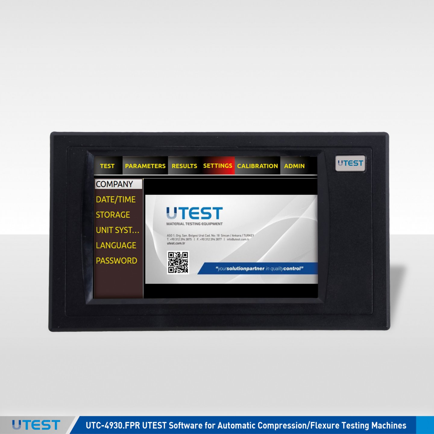
Product Code
|
USOFT-4930.FPR |
UTEST Software for Automatic Concrete&Cement Compression/Flexure Testing Machines |
Utest USOFT-4930.FPR Software has been designed for data acquisition, processing controlling, presentation and reporting compression, flexure, splitting tensile strength tests of construction materials such as concrete, cement, masonry units/blocks with appropriate Automatic Compression/Flexure Testing Machines and also with a computer.
This software provides data acquisition and management for compression, flexure and splitting tensile tests of construction materials such as concrete, cement, bricks.
The advanced functions for data base management provide an easy navigation of all saved data.
The test results certificate includes all descriptive information.
Therefore, test parameters can be set and details about the test carried out such as client details, test type, specimen type, user info and other information required can be entered and printed out as well as test report and graph.
Following tests can be done with the USOFT-4930.FPR Software;
- Compressive Strength of Concrete Cylinders / Cubes
- Flexural Strength of Concrete Beams
- Flexural Strength of Concrete Kerbs
- Tensile Splitting Strength of Concrete Cylinders / Cubes
- Tensile Splitting Strength of Concrete Paving Blocks
- Compressive Strength of Masonry Units/Blocks
- Flexural Strength of Concrete Flagstones/Slabs
- Compressive Strength of Hydraulic-Cement Mortars
- Flexural Strength of Hydraulic-Cement Mortars
Detailed information of the following properties of USOFT-4930.FPR software, please look at the “General Properties of Utest USOFT Series Softwares Softwares” pages.
- Multi-language support and customizable user interface
- User identification and authorization
- Unlimited test result storage capacity in one test file
- Exporting test results to database
- Advanced test graphical interface
- Option to store and recall test information
- Modification of test machine parameters using the software
- Able to save frequently used texts in memory and recall them when necessary
- Exporting reports and graphs
- Flexible report and graph formats
- Help and user manual display


34. Jigs for Compression and Flexure Tests
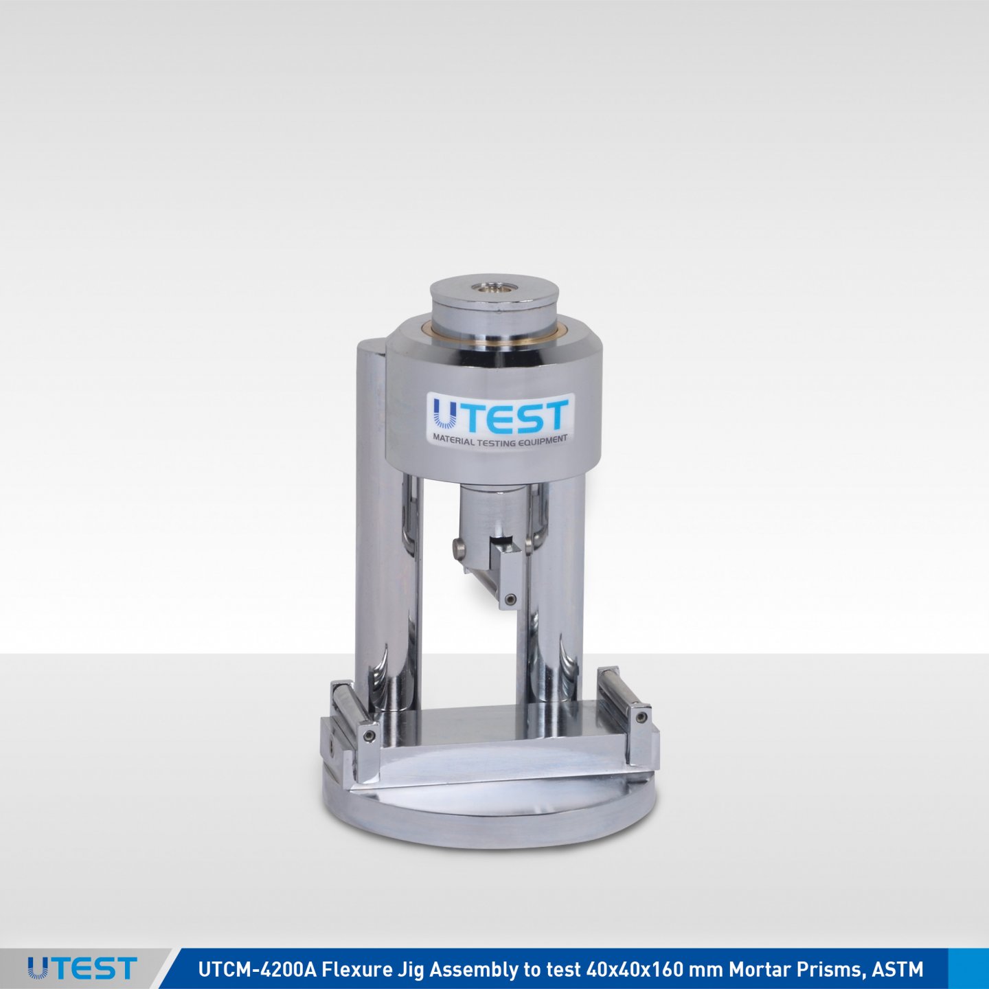
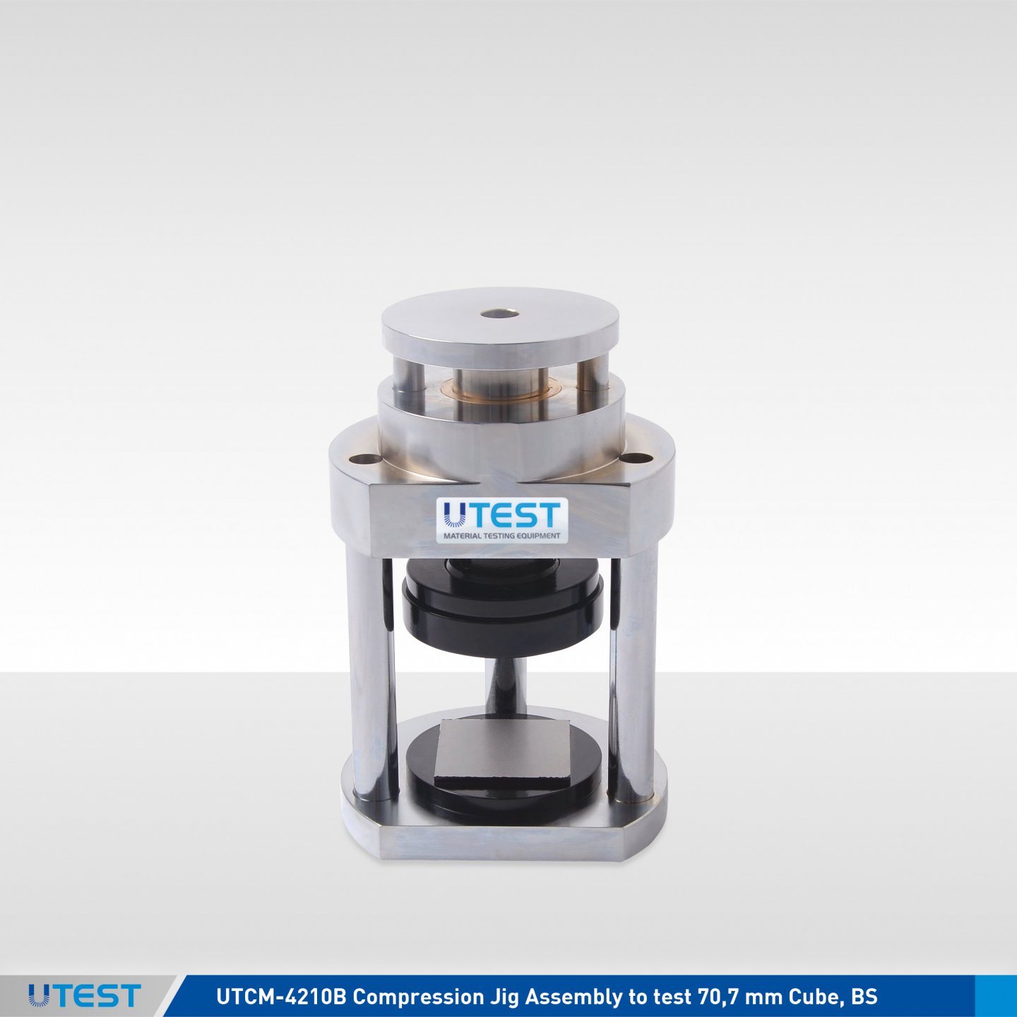
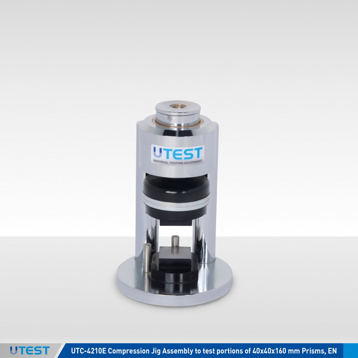
Product Code
|
UTCM-4200A |
Flexure Jig Assembly to test 40x40x160 mm Mortar Prisms, ASTM |
|
UTCM-4200E |
Flexure Jig Assembly to test 40x40x160 mm Mortar Prisms, EN |
|
UTCM-4210A |
Compression Jig Assembly to test 50 mm (2”) Mortar Cubes, ASTM |
|
UTCM-4210E |
Compression Jig Assembly to test portions of 40x40x160 mm Prisms, EN |
|
UTCM-4210B |
Compression Jig Assembly to test 70,7 mm Cube, BS |
Standards
EN 196-1, 459-2, 1015-11, 13454-2; ASTM C109, C348, BS 4550-3.4
35. Plunger Penetration Apparatus
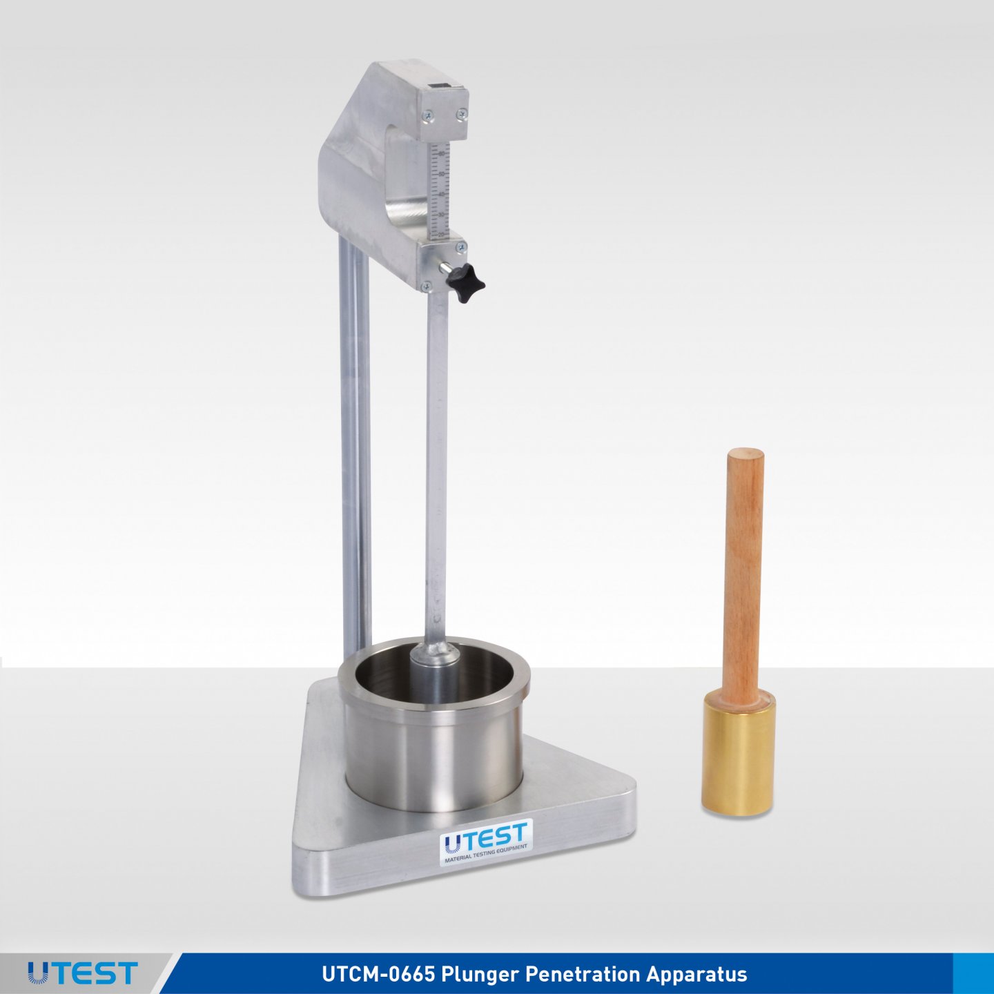
Product Code
|
UTCM-0665 |
Plunger Penetration Apparatus |
|
UTCM-0662E |
Tamper EN Ø 40x200 mm 250 gr |
Standards
EN 413-2, 459-2, 1015-4
The UTEST Plunger Penetration Apparatus is used to determine the consistency of fresh mortar, building lime and masonry cement. The test apparatus consists of a base to place the test cup and a vertical column holding the penetration plunger assembly. The drop default height is adjusted to 100 mm. The plunger assembly weight is 90 g.
The Plunger Penetration Apparatus is supplied complete with;
- Test cup, Ø80 mm x 70 mm
- Tamper
|
Dimensions |
200x200x600 mm |
|
Weight (approx.) |
6 kg |
36. Air Entrainment Meter for Mortar
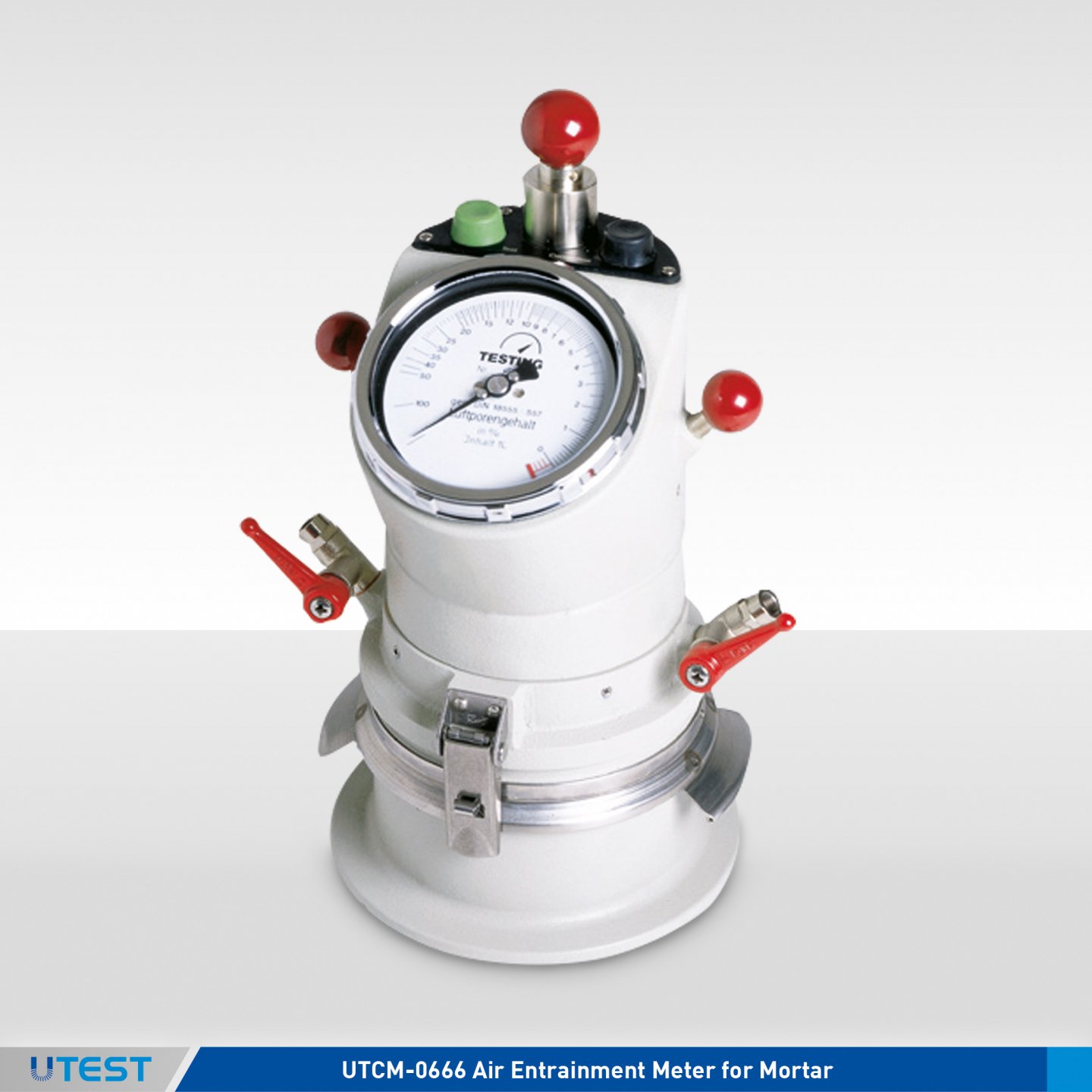
Product Code
|
UTCM-0666 |
Air Entrainment Meter for Mortar 1 lt. |
|
UTCM-0662E |
Tamper EN Ø 40x200 mm 250 gr |
Standards
EN 413-2, 459-2, 1015-7
The UTCM-0666 Air Entrainment Meter for Mortar is used for determining the air content of cement paste, cement mortar and lime mortar.
The air entrainment meter is manufactured from cast aluminum, the upper part and the lower test pot are held together with an air-tight seal which are easily adjusted by using the two spring clamps.
The pressure gauge is installed in the head of the meter and the scale works in the 0-20 volumetric % range. The air is compressed with a hand pump installed in the system and the smart configuration of the test and correction buttons enables fast and simple testing.
|
Dimensions |
200x200x320 mm |
|
Weight (approx.) |
3,5 kg |
37. Solid Mould
Product Code
|
UTCM-0670 |
Solid Mould |
Standards
EN 413-2
The UTCM-0670 Solid Mould is used to determine the water retention of masonry cement specimens. Supplied with a glass plate.
|
Dimensions |
150x150x40 mm |
|
Weight (approx.) |
0,2 kg |
38. Apparatus For Reactivity of Quicklime
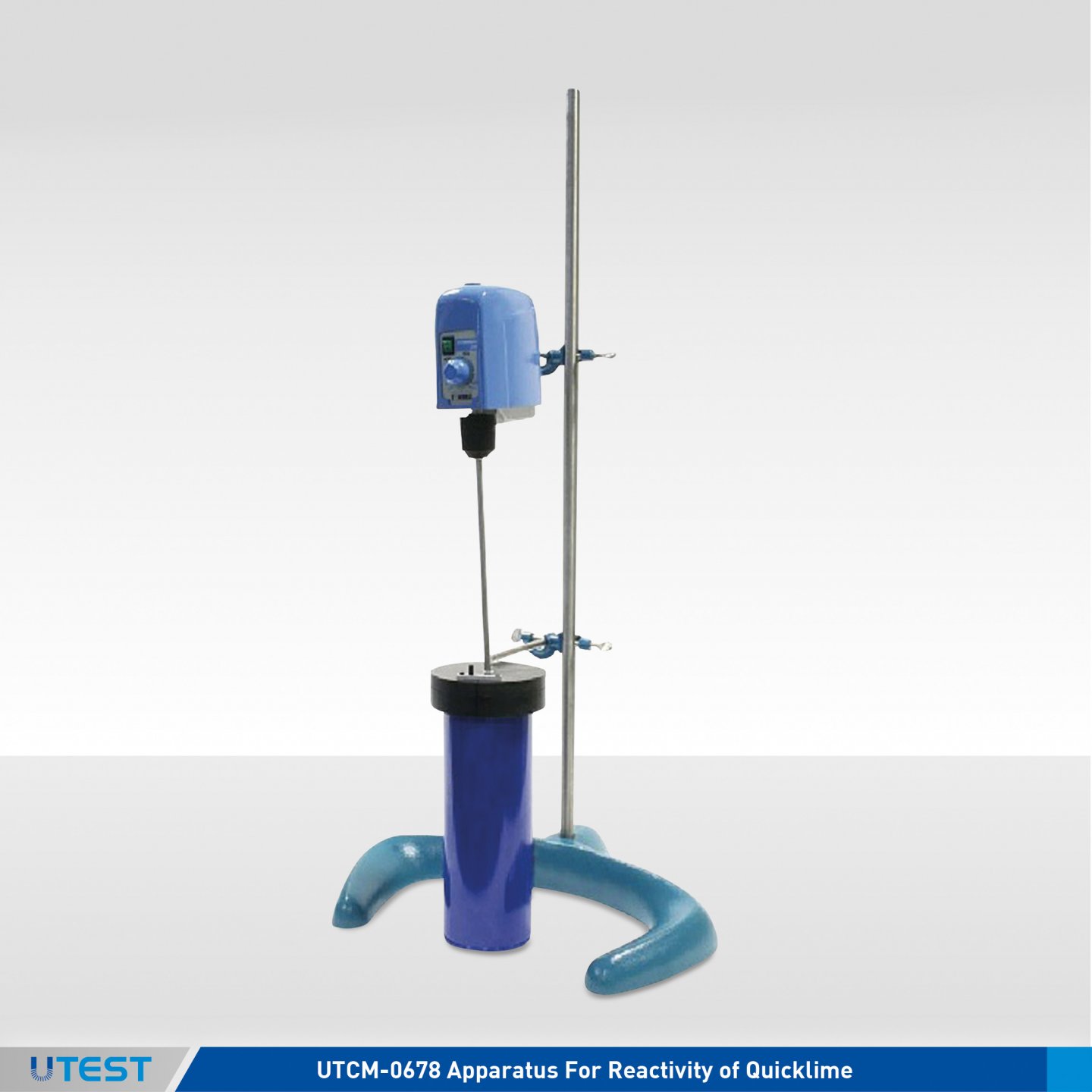
Product Code
|
UTCM-0678 |
Apparatus For Reactivity of Quicklime, 220-240 V 50-60 Hz |
|
UTCM-0679 |
Apparatus For Reactivity of Quicklime with Advanced Datalog Thermometer EN 459-2, 110-240 V 50-60 Hz 1 ph |
Standards
EN 459-2
The UTCM-0678 and UTCM-0679 Reactivity of Quicklime Apparatus are used to determine the reactivity of ground quicklime on slaking.
These Apparatus consist essentially of a Dewar vessel, 1000 ml cap, stirring motor, calibrated thermometer, stand and accessories.
Two models are available:
- UTCM-0678 is supplied with digital thermometer
- UTCM-0679 is supplied with advanced datalog thermometer, temperature probe, serial cable for PC connection and dedicated software for download data
|
Dimensions |
350x300x800 mm |
|
Weight (approx.) |
9,5 kg |
39. Bulk Density Apparatus
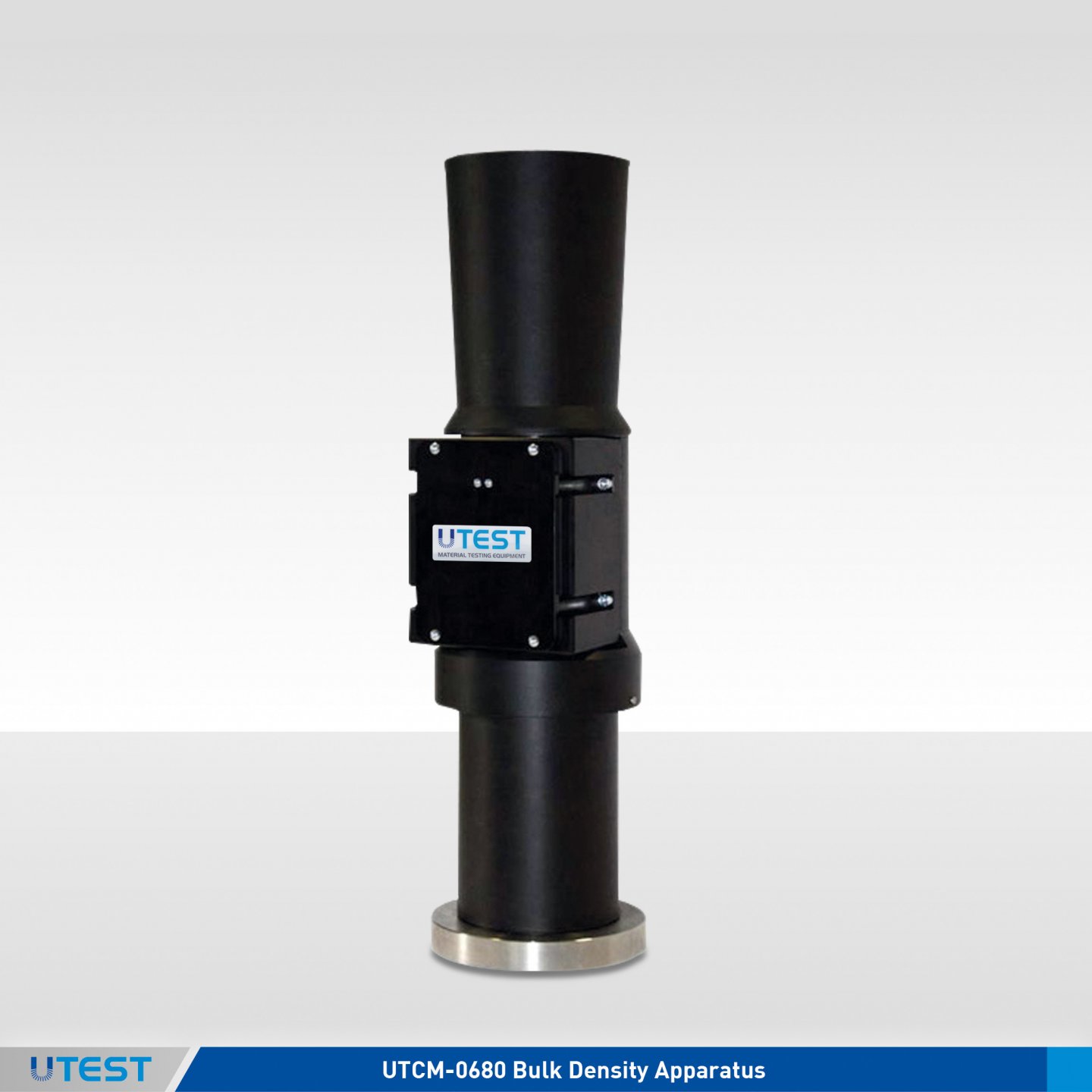
Product Code
|
UTCM-0680 |
Bulk Density Apparatus |
Standards
EN 459-2
The bulk density of lime is of interest for storage and packaging and for determining volume and capacity of mixing equipment necessary for processing the material.
The UTCM-0680 Bulk Density Apparatus is designed to determine bulk density of lime by allowing a sample to fall from a standard height into a volumetric container.
The apparatus consists of a hopper, 1 liter capacity cylindrical container and a spring-loaded yoke.
|
Dimensions |
250x250x750 mm |
|
Weight (approx.) |
2 kg |
40. Slaking Vessel
Product Code
|
UTCM-0681 |
Slaking Vessel, EN |
Standards
EN 459-2
UTCM-0681 Slaking Vessel is used to determine the yield of lime by leaving the lime sample to slake into. Stainless steel made and double walled insulated. The cylinder has inside dimensions dia. 113 mm by 120 mm deep without cover. Supplied complete with cover.
|
Dimensions |
160x160x200 |
|
Weight (approx.) |
4 kg |
41. Flow Cone Apparatus
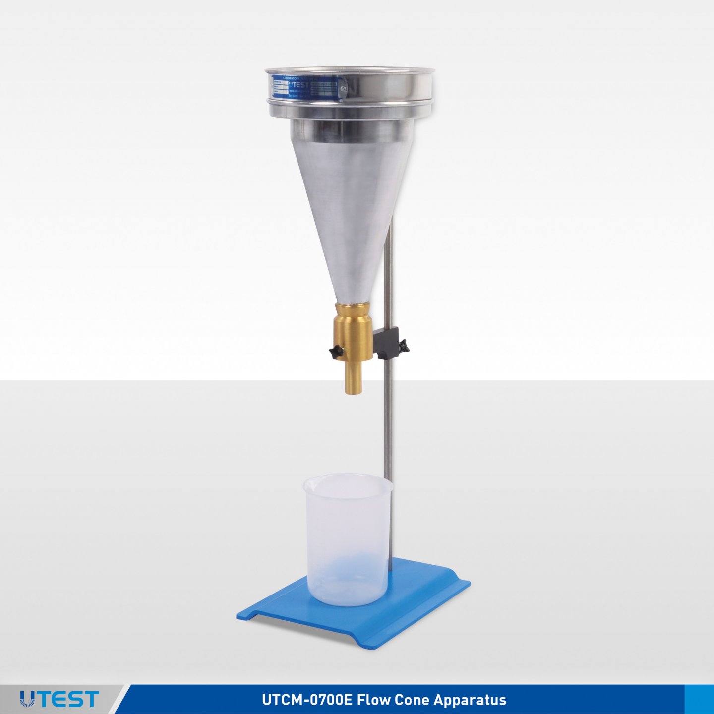
Product Code
|
UTCM-0700E |
Flow Cone Apparatus |
|
UTCM-0701E |
Flow Cone |
|
UTCM-0702E |
Ø:8 mm Nozzle |
|
UTCM-0703E |
Ø:9 mm Nozzle |
|
UTCM-0704E |
Ø:10 mm Nozzle |
|
UTCM-0705E |
Ø:11 mm Nozzle |
|
UTCM-0706E |
Ø:13 mm Nozzle |
Standards
EN 445
UTCM-0700E Flow Cone Apparatus is used for determining the flow properties of grouts, mortars, muds and other fluid materials.
The Flow Cone Appratus is supplied complete with;
- Cone, Sieve 1,5 mm
- Cup 1 lt
- Nozzle 10 mm
- Fitting Bush
- Stand

Ø:8, 9, 10, 11, 13 mm Nozzle
|
Dimensions |
250x250x600 mm |
|
Weight (approx.) |
10 kg |
42. Marsh Funnel Viscometer
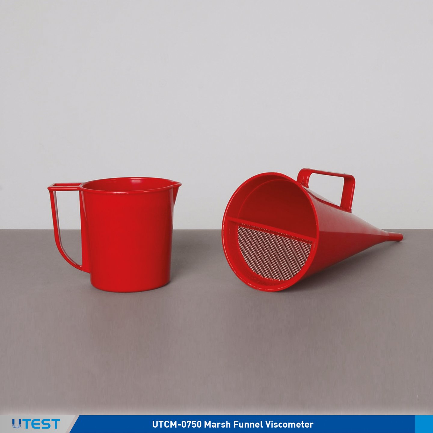
Product Code
|
UTCM-0750 |
Marsh Funnel Viscometer |
Standards
ASTM D6910, API Recommended Practice 13B-1
The UTCM-0750 Marsh Funnel Viscometer is used for the determination of flow time by the use of flow cups of fluid materials such as paint, varnish etc. Manufactured from breakresistant rugged plastic to avoid deformations on temperature changes so the volumetric accuracy is maintained. Accurate measurements are taken using the metal orifice.
To avoid the operator’s hands coming into contact with the test material, a handle is provided. Supplied complete with 1 liter capacity plastic measuring cup.
|
Top Diameter |
150 mm |
|
Nozzle Length |
50 mm |
|
Internal Diameter |
5 mm |
|
Total Length |
355 mm |
|
Weight (approx.) |
0,5 kg |
43. Mud Balance
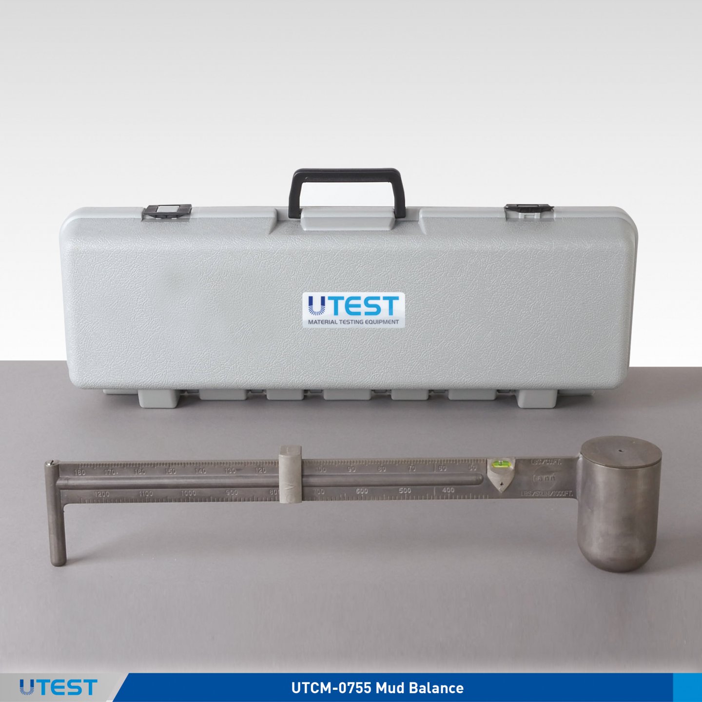
Product Code
|
UTCM-0755 |
Mud Balance |
Standards
API Recommended Practice Procedure
The UTCM-0755 Mud Balance, an ideal equipment for site applications, provides an accurate and easy method for determining the mud density. The accuracy of the readings is not affected by the temperature of the drilling mud.
The equipment consists of a base and a graduated arm with an integral spirit level, counter weight, cup, lid, rider, knife-edge. Supplied with a special plastic carrying case which can be used to stabilize the equipment at the working position.
|
Dimensions |
550x110x100 mm |
|
Weight (approx.) |
1 kg |
44. Wet Sieving Apparatus
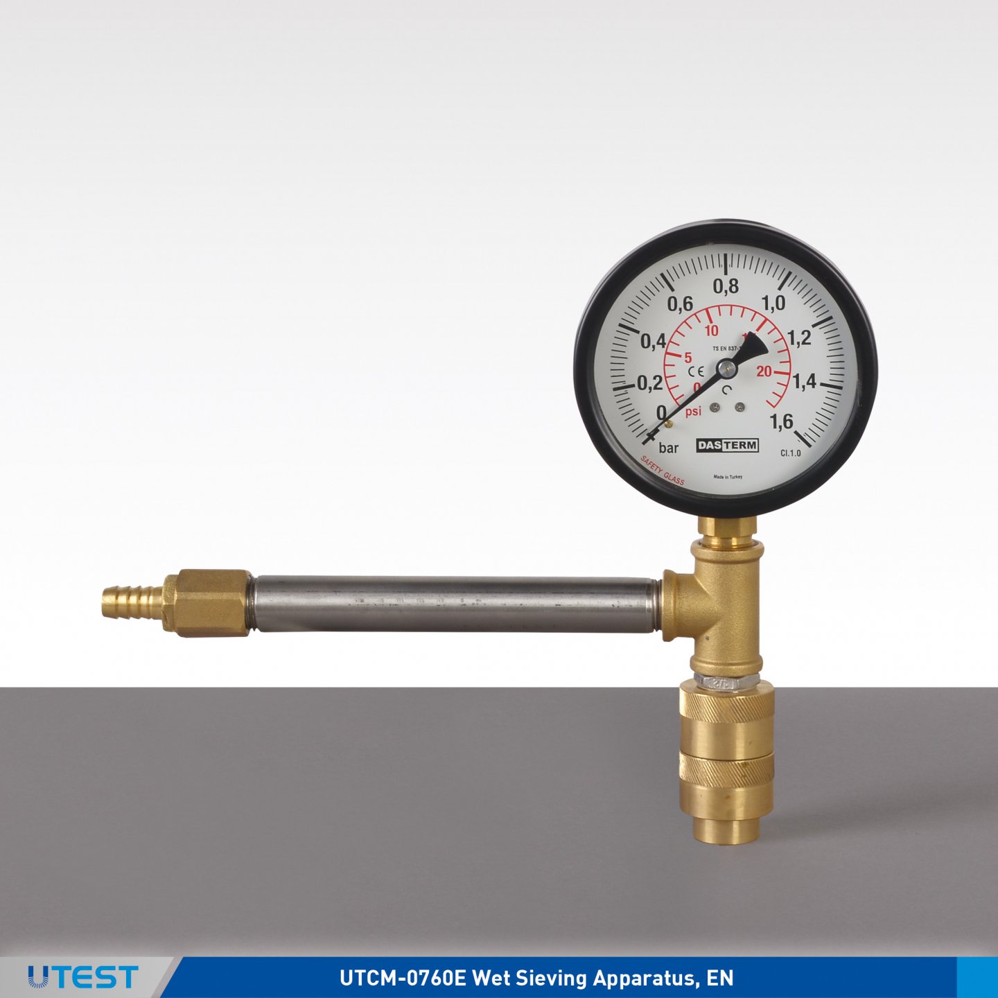
Product Code
|
UTCM-0760E |
Wet Sieving Apparatus, EN |
Standards
EN 451-2; ASTM C430, D1514; AASHTO T192
The UTCM-0760E Wet Sieving Apparatus is used for determining the fineness of fly ash. The apparatus comprises of a special stainless steel sieve, 0.045 mm opening, a spray nozzle Ø 17.5 mm with 17 holes Ø 0.5 mm oriented and spaced to conform to the standards. Supplied complete with a pressure gauge Ø 80 mm and fittings for connection to the water supply.
|
Dimensions |
250x150x150 mm |
|
Weight (approx.) |
2 kg |
UTEST AGGREGATE
1. Fully-Automated Sheartrac III System

Product Code
ShearTrac III
The ShearTrac IIITM system is capable of performing the consolidation and shear- ing phases of a 305 mm x 305 mm (12 x 12 in. by 200mm(8.0 in) height direct shear test under automatic control for soils and geosynthetics (geomembrane, geotextile, GCL, geogrid, etc.) as well as for deter- mining the interface frictional properties of soil and geosynthetics, and internal friction of GCLs.
The system consists of a computer con- trolled unit that utilizes a micro stepper motor to apply the horizontal loads. Ver- sions of the unit are available to test loads up to 50 kN (10,000 lbs). Builtin elec- tronics control test and display data in real time. The system is capable of applying a constant rate of strain or stress at any displacement rate up to 15mm (0.6 inch) per minute. The computer controlled program runs under latest Windows. It includes the capability to display the current status of latest and graphically portray the progress of the test in real time. The system also includes the capa- bility for the operator to alter the test process and conditions at any stage during the test.
This is a turnkey system that includes hardware and software for recording all test input data and settings of selected test parameters, performing standard engineering calculations on the data, and producing graphically plotted and printed output in the standard Corps format, in accordance with ASTM D5321, D6243 and BS 1377 standards.
Applicable Test Standards
- ASTM D-5321 and D-6243
- ASTM 3080/T236
- BS 1377
Features / Benefits
- Built-in end clamps for geosynthetics testing
- Optional grip plates for true internal friction determination for GCLs
- Linear bearings for minimum horizontal friction
- Two sets of limit switches to prevent over traveling
- Built-in 4-channel data acquisition with 16-bit resolution
- Two LCD display
- Two displacement transducers with 100 mm (4.00 in.) range and 0.002 mm (0.00008 in.) resolution
- Two universal shear web type load cells
- Accurate displacement rate control from 0.00003 to 10 mm per minute (0.000001 to 0.4 in. per minute)
- Built-in electronic controls for automatic display of data and control of test
- Windows XP, or Vista, 7 friendly user interface
- Fully incremental consolidation test capability
Technical Specifications
|
Capacity |
50 kN (10,500 lbs.) |
|
Vertical Motor |
Stepper motor with built-in controls for vertical load |
|
Horizontal Mot. |
Stepper motor with built-in controls for horizontal load |
|
Speed Range |
90 mm (3.5 in.) resolved to 0.002 mm (0.00008 inches) |
|
Vertical Travel |
90 mm (3.5 in.) resolved to 0.002 mm (0.00008 inches) |
|
Horizontal Travel |
90 mm (3.5 in.) resolved to 0.002 mm (0.00008 inches) |
|
Power |
110/220 V, 50/60 Hz, 1phase |
Models
|
ST-10000 |
50 kN (10,000 lbs.) frame capacity in both directions. |
Accessories
|
Geo-NETTM-PC |
Network card and cable to link ShearTrac III to PC |
|
Shear |
Software package to automatically run consolidation and direct shear test on ShearTrac III |
|
Shear.report |
Editing/reporting software package |
|
Gripping Plates |
Optional for GCL testing |
2. Riffle Boxes
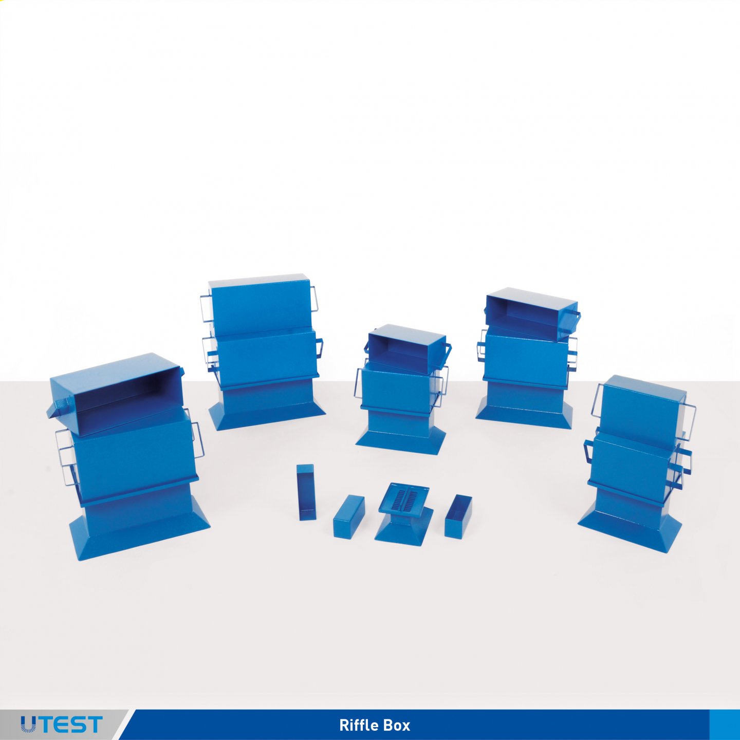
Product Code
|
UTA-0338 |
Riffle Box 5 mm |
|
UTA-0340 |
Riffle Box 7 mm |
|
UTA-0341 |
Riffle Box 13 mm |
|
UTA-0342 |
Riffle Box 15 mm |
|
UTA-0343 |
Riffle Box 19 mm |
|
UTA-0344 |
Riffle Box 25 mm |
|
UTA-0345 |
Riffle Box 30 mm |
|
UTA-0346 |
Riffle Box 38 mm |
|
UTA-0347 |
Riffle Box 45 mm |
|
UTA-0348 |
Riffle Box 50 mm |
|
UTA-0349 |
Riffle Box 64 mm |
|
UTA-0350 |
Riffle Box 75 mm |
Standards
EN 932-2; ASTM C702; BS 812:1, 1377:1, 1924:1
Riffle boxes are used for dividing aggregates into 2 equal homogenous quantity for testing. The Riffle Box is electrostatically painted and manufactured to meet the relevant International standard both in the slot width and number of slots.
The Riffle Boxes are supplied complete with;
- Containers with Handles, 3 pcs
|
|
Aperture |
Number of Slots |
Weight |
Dimensions |
|
UTA-0338 |
5 mm |
16 |
12 kg |
100x130x120 mm |
|
UTA-0340 |
7 mm |
12 |
14 kg |
110x140x140 mm |
|
UTA-0341 |
13 mm |
12 |
33 kg |
190x260x330 mm |
|
UTA-0342 |
15 mm |
12 |
33 kg |
190x280x330 mm |
|
UTA-0343 |
19 mm |
10 |
36 kg |
220x280x360 mm |
|
UTA-0344 |
25 mm |
10 |
39 kg |
220x340x390 mm |
|
UTA-0345 |
30 mm |
10 |
40 kg |
220x390x400 mm |
|
UTA-0346 |
38 mm |
8 |
56 kg |
320x410x560 mm |
|
UTA-0347 |
45 mm |
8 |
57 kg |
410x480x570 mm |
|
UTA-0348 |
50 mm |
8 |
60 kg |
320x550x600 mm |
|
UTA-0349 |
64 mm |
8 |
60 kg |
350x640x600 mm |
|
UTA-0350 |
75 mm |
8 |
58 kg |
360x700x580 mm |
3. Laboratory Type Crusher and Grinder
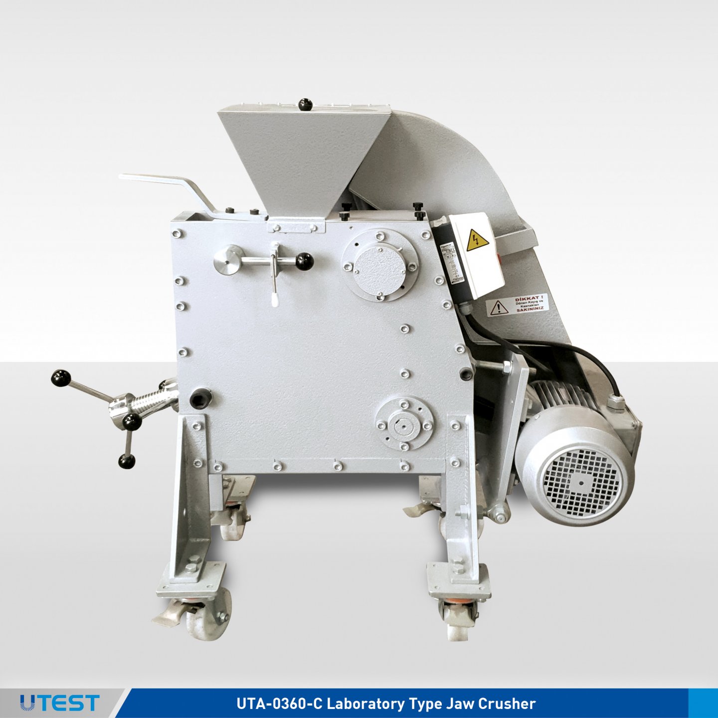
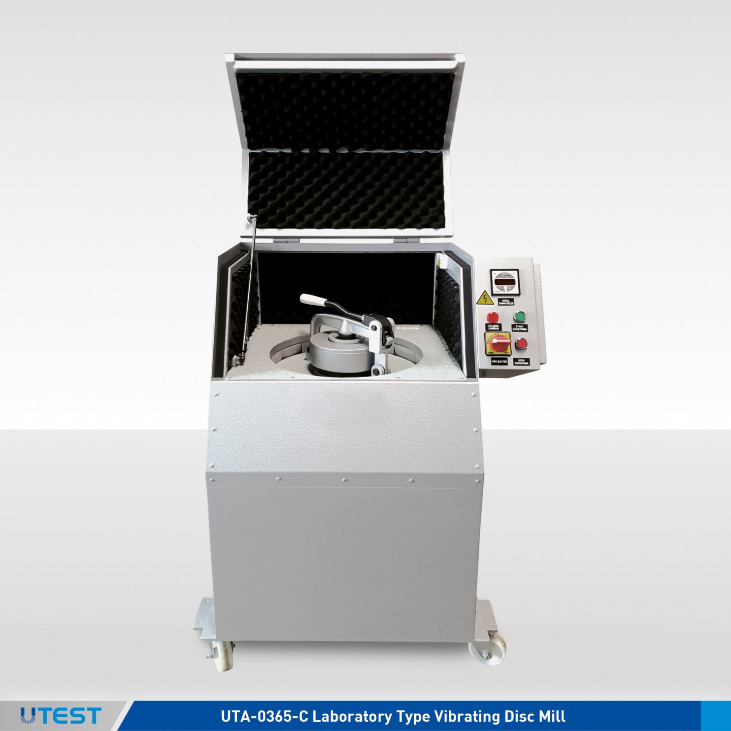
Product Code
|
UTA-0360-C |
Laboratory Type Jaw Crusher, 380 V 50 Hz, 3ph |
|
UTA-0365-C |
Laboratory Type Vibrating Disc Mill, 380 V 50 Hz, 3ph |
UTA-0360 is used for crushing, UTA-0365 is used for grinding cement clinker, ceramics, basalt, chamotte, construction materials, alloys, coal, coke, feldspar, glass and various materials in the laboratory when smaller sample sizes are required for testing. Three models are available (see Technical Specifications) depending on different feed sizes, output grain sizes and capacity requirements.
|
Product Code |
UTA-0360-C |
UTA-0365-C |
|
Feed Size |
100 mm |
< 15 mm |
|
Output Grain Size |
< 500 μm 0-8 mm, adjustable |
38 μm max. 10 μm |
|
Capacity |
150 kg/h |
(*) |
|
Dimensions |
482x1044x1015 mm |
650x730x1150 mm |
|
Weight (approx.) |
250 kg |
330 kg |
|
Power |
4 HP |
1,5 HP |
(*) Dijital setting of grinding time from 0 up to 999 h or 999 min. or 999 seconds
4. Flakiness Index Sieve Sets BS
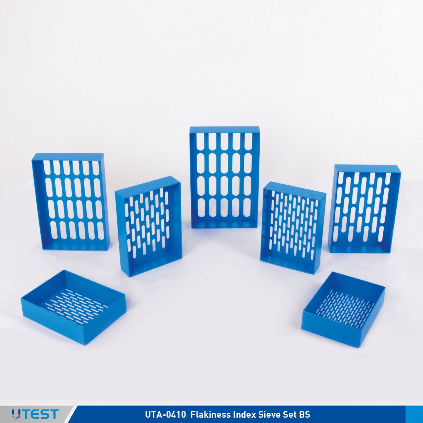
Product Code
|
UTA-0410 |
Flakiness Index Sieve Set, BS |
|
UTA-0411 |
Flakiness Index Sieve BS 4.9x30 mm Slot Size |
|
UTA-0412 |
Flakiness Index Sieve BS 7.2x40 mm Slot Size |
|
UTA-0413 |
Flakiness Index Sieve BS 10.2x50 mm Slot Size |
|
UTA-0414 |
Flakiness Index Sieve BS 14.4x60 mm Slot Size |
|
UTA-0415 |
Flakiness Index Sieve BS 19.7x80 mm Slot Size |
|
UTA-0416 |
Flakiness Index Sieve BS 26.3x90 mm Slot Size |
|
UTA-0417 |
Flakiness Index Sieve BS 33.9x100 mm Slot Size |
Standards
BS 812-105.1
Aggregate particles are considered as flaky when their thickness is less than 0.6 of their mean sieve size. Aggregate to be classified is separated into seven sieve fractions from 6.3 to 63 mm and each fraction is examined separately. The dimensions of each sieve comply with the relevant International Standard, manufactured from heavy gauge steel sheet and coated with electrostatic paint. The accuracy of the slot size is better than 0.1 mm.
UTA-0410 Flakiness Index Sieve Set consists of 7 sieves.
For sample preperation 6.3, 10, 14, 20, 28, 37.5, 50 and 63 mm aperture sizes test sieves should be ordered seperately.
|
|
Slot Size (wxl) |
Weight (approx.) |
Dimensions |
|
UTA-0411 |
4.9x30 mm |
2 kg |
470x320x80 mm |
|
UTA-0412 |
7.2x40 mm |
2 kg |
220x300x80 mm |
|
UTA-0413 |
10.2x50 mm |
2 kg |
230x310x80 mm |
|
UTA-0414 |
14.4x60 mm |
2 kg |
250x330x80 mm |
|
UTA-0415 |
19.7x80 mm |
2 kg |
280x380x80 mm |
|
UTA-0416 |
26.3x90 mm |
3 kg |
290x420x80 mm |
|
UTA-0417 |
33.9x100 mm |
3 kg |
310x470x80 mm |
5. Grid Sieve Sets (Flakiness Index Sieve EN)
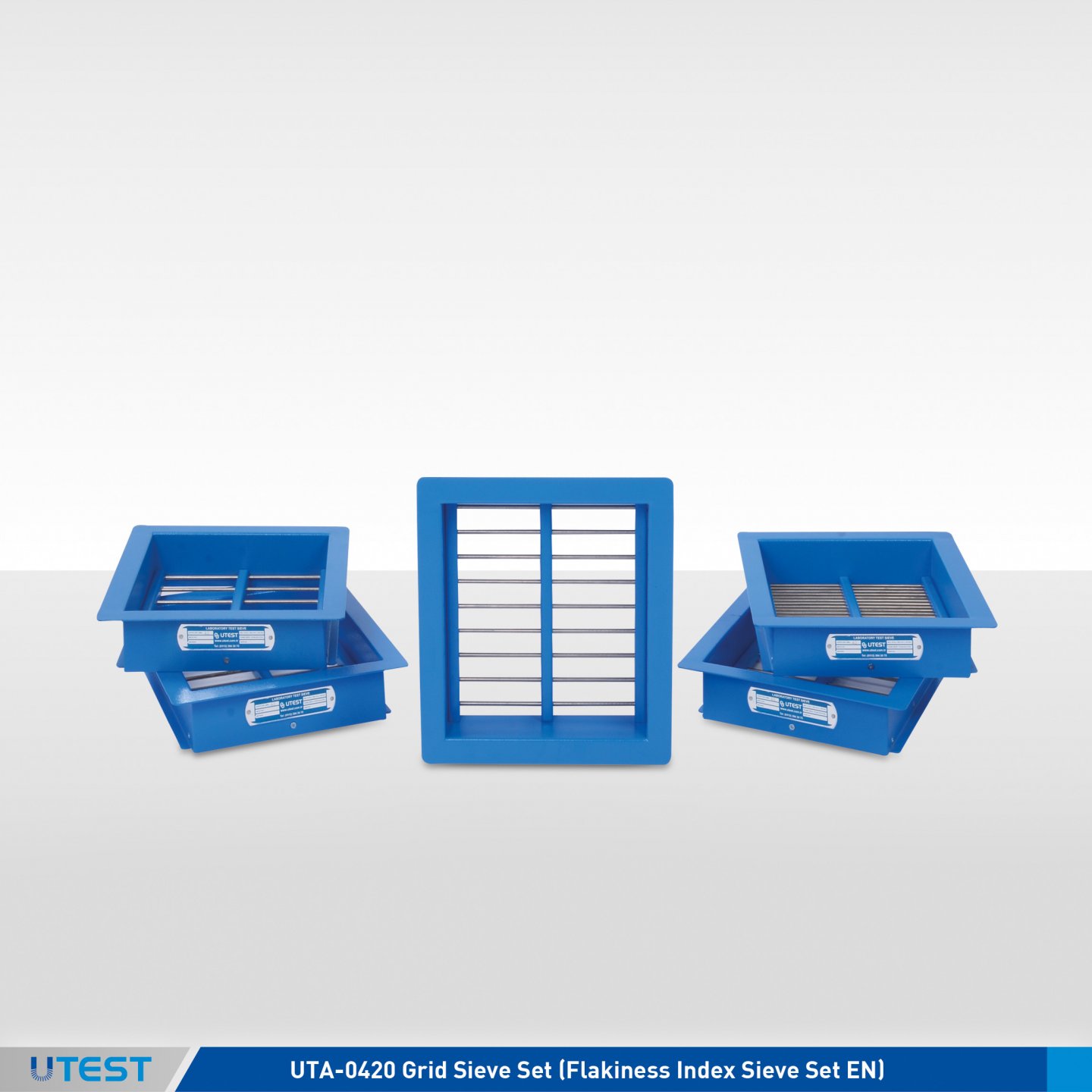
Product Code
|
UTA-0420 |
Grid Sieve Set (Flakiness Index Sieve Set EN) |
|
UTA-0421 |
Grid Sieve (Flakiness Index Sieve EN) 2.5 mm |
|
UTA-0422 |
Grid Sieve (Flakiness Index Sieve EN) 3.15 mm |
|
UTA-0423 |
Grid Sieve (Flakiness Index Sieve EN) 4 mm |
|
UTA-0424 |
Grid Sieve (Flakiness Index Sieve EN) 5 mm |
|
UTA-0425 |
Grid Sieve (Flakiness Index Sieve EN) 6.3 mm |
|
UTA-0426 |
Grid Sieve (Flakiness Index Sieve EN) 8 mm |
|
UTA-0427 |
Grid Sieve (Flakiness Index Sieve EN) 10 mm |
|
UTA-0428 |
Grid Sieve (Flakiness Index Sieve EN) 12.5 mm |
|
UTA-0429 |
Grid Sieve (Flakiness Index Sieve EN) 16 mm |
|
UTA-0430 |
Grid Sieve (Flakiness Index Sieve EN) 20 mm |
|
UTA-0431 |
Grid Sieve (Flakiness Index Sieve EN) 25 mm |
|
UTA-0432 |
Grid Sieve (Flakiness Index Sieve EN) 31.5 mm |
|
UTA-0433 |
Grid Sieve (Flakiness Index Sieve EN) 40 mm |
|
UTA-0434 |
Grid Sieve (Flakiness Index Sieve EN) 50 mm |
Standards
EN 933-3; NF P18-561; UNI 8520-18; NLT 354
Used for the determination of the flakiness index of the aggregate. Consisting of an electrostatically painted frame and 5 mm diameter stainless steel bars with apertures state below.
For sample preperation 4.5, 6.3, 8, 10, 12.5, 16, 20, 25, 31.5, 40, 50, 63, 80 and 100 mm aperture sizes test sieves should be ordered seperately.
|
|
Aperture |
Weight |
Dimensions |
|
UTA-0421 |
2.5 mm |
3 kg |
320x340x80 mm |
|
UTA-0422 |
3.15 mm |
3 kg |
320x340x80 mm |
|
UTA-0423 |
4 mm |
3 kg |
320x340x80 mm |
|
UTA-0424 |
5 mm |
3 kg |
320x340x80 mm |
|
UTA-0425 |
6.3 mm |
3 kg |
320x340x80 mm |
|
UTA-0426 |
8 mm |
3 kg |
320x340x80 mm |
|
UTA-0427 |
10 mm |
3 kg |
320x340x80 mm |
|
UTA-0428 |
12.5 mm |
3 kg |
320x340x80 mm |
|
UTA-0429 |
16 mm |
3 kg |
320x340x80 mm |
|
UTA-0430 |
20 mm |
3 kg |
320x340x80 mm |
|
UTA-0431 |
25 mm |
3 kg |
320x340x80 mm |
|
UTA-0432 |
31.5 mm |
3 kg |
320x340x80 mm |
|
UTA-0433 |
40 mm |
3 kg |
320x340x80 mm |
|
UTA-0434 |
50 mm |
3 kg |
320x340x80 mm |
6. Thickness Gauge (Flakiness Index) BS
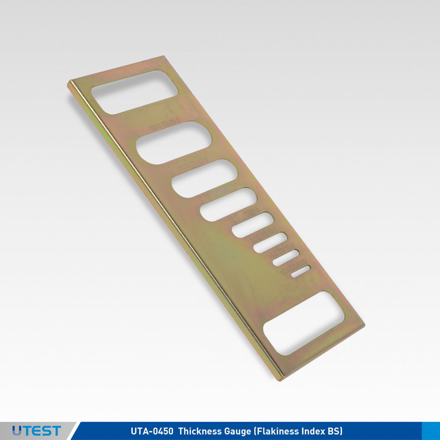
Product Code
|
UTA-0450 |
Thickness Gauge (Flakiness Index BS) |
Standards
BS 812-105.1
Thickness Gauge is used to determine if the aggregate particles are to be considered as flaky, i.e. their thickness is less than 0.6 of their nominal size.
The aggregate to be classified is separated into seven sieve fractions from 6.3 to 63 mm, and each fraction is examined separately. Slot sizes are 4.9 x 30 mm, 7.2 x 40 mm, 10.2 x 50 mm, 14.4 x 60 mm, 19.7 x 80 mm, 26.3 x 90 mm and 33.9 x 100 mm.
|
Dimensions |
310x130x10 mm |
|
Weight (approx.) |
0,4 kg |
7. Efflux Index Apparatus (Flow Coefficient of Fine Aggregates)
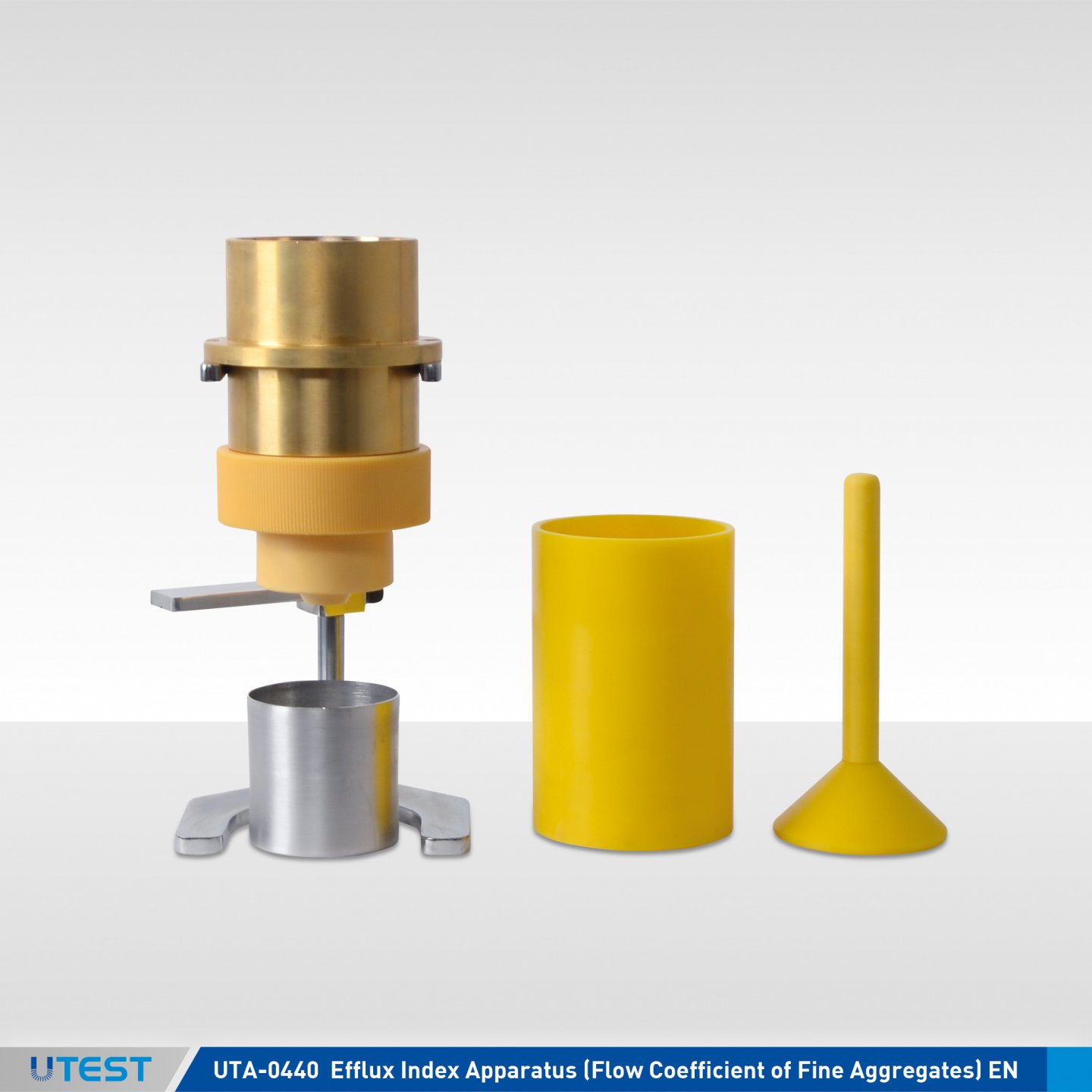
Product Code
|
UTA-0440 |
Efflux Index Apparatus (Flow Coefficient of Fine Aggregates), EN |
Standards
EN 933-6
UTA-0440 Efflux Index (Flow Coefficient of Fine Aggregates) Apparatus is used to obtain information about the shape and the angularity of grains of fine aggregates.
The flow coefficient of an aggregate is the time, expressed in seconds, for a specified volume of aggregate to flow through a given opening, under specified conditions using a standard apparatus.
Efflux Index (Flow Coefficient of Fine Aggregates) Apparatus consist of a control shutter, acylindrical feed hopper, a cylindrical body, a cone and a metal stand.
|
Dimensions |
160x170x410 mm |
|
Weight (approx.) |
6 kg |
8. Length Gauge (Elongation Index BS)
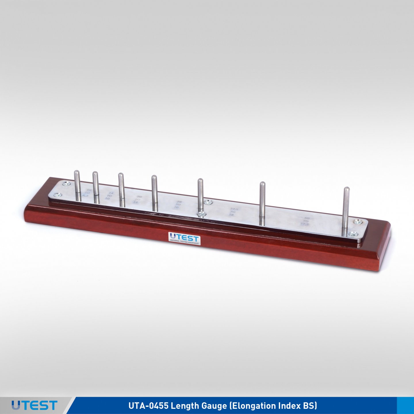
Product Code
|
UTA-0455 |
Length Gauge (Elongation Index BS) |
Standards
BS 812-105.2
Length Gauge (Elongation Index BS), is used for determining the elongation index of aggregates. The particle is elongated when its length (longest dimension) is more than 1.8 o the midsize of the sieve fraction. The aggregate to be classified is separated into six sieve fractions from 6.3 to 50 mm and each fraction is examined separately.
|
Dimensions |
70x370x70 mm |
|
Weight (approx.) |
0,90 kg |
9. Shape Index Caliper
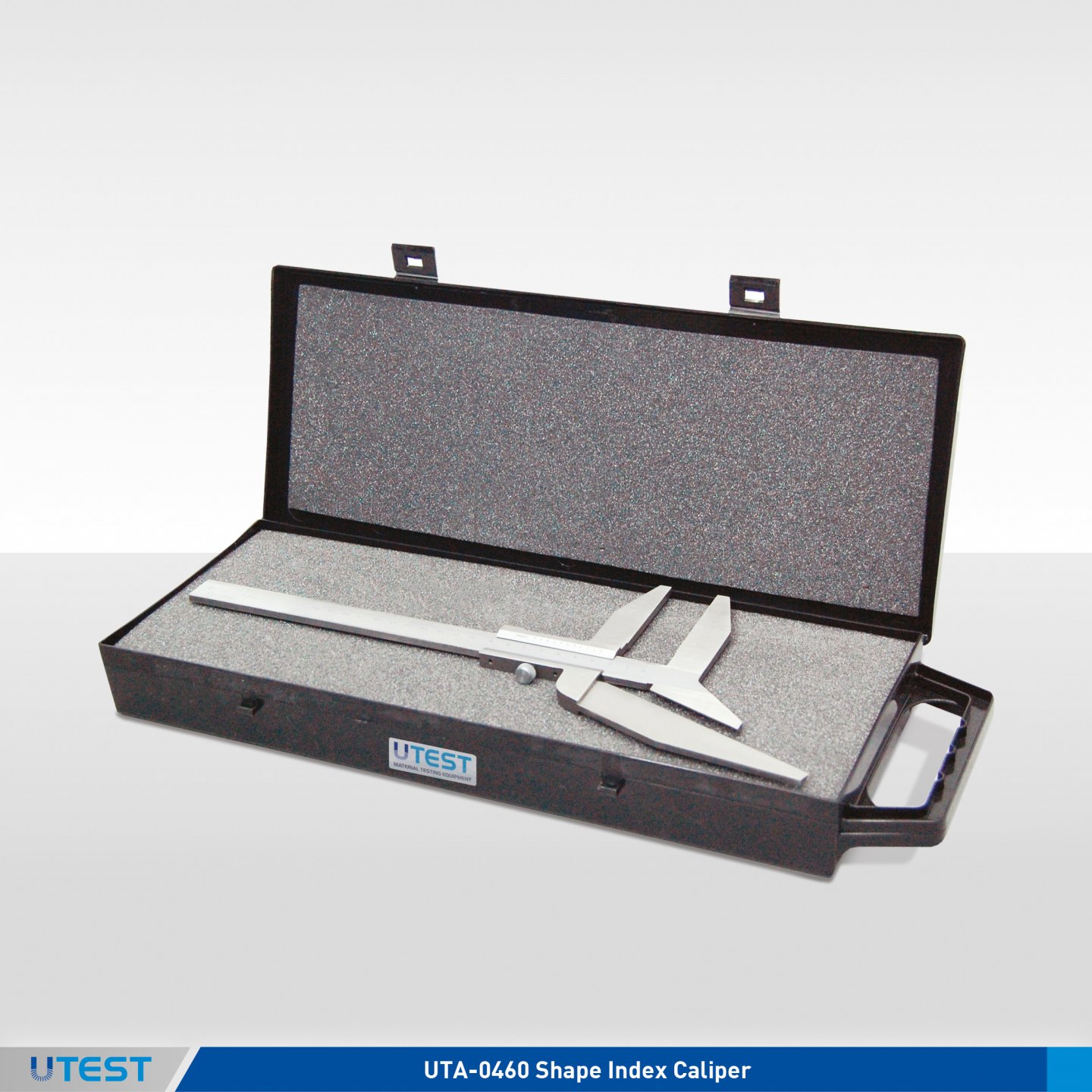
Product Code
|
UTA-0460 |
Shape Index Caliper |
Standards
EN 933-4; DIN 4226; CNR No.95; NLT 354
Shape Index Caliper is used for the determination of the shape factor of aggregates.
Measurement range is 200 mm and graduated with 0.05 mm increments.
|
Dimensions |
170x470x50 mm |
|
Weight (approx.) |
1 kg |
10. Sand Equivalent Test Sets
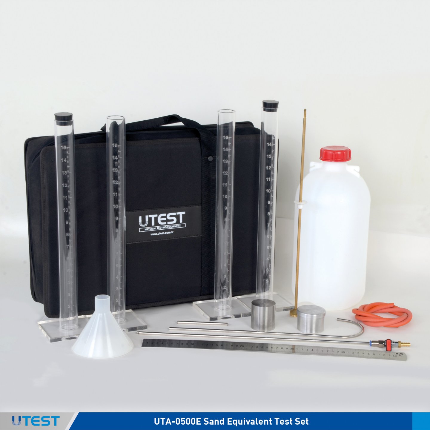
Product Code
|
UTA-0500E |
Sand Equivalent Test Set, EN Model |
|
UTA-0500A |
Sand Equivalent Test Set, ASTM Model |
|
UTA-0502E |
Sand Equivalent Measuring Two Graduated Cylinder, EN |
|
UTA-0502A |
Sand Equivalent Measuring Graduated Cylinder, ASTM |
|
UTGH-1425 |
Moisture Content Tin Sand Equivalent Measuring Tin with Lid, Aluminium, Ø:55 mm x h:35 mm |
|
UTA-0506 |
Sand Equivalent Siphon Assembly |
|
UTA-0507E |
Sand Equivalent Test Plunger Assembly, EN |
|
UTA-0507A |
Sand Equivalent Weighted Foot Assembly, ASTM |
|
UTA-0515 |
Washing and Flocculating Solution (Stock Solution), 1 lt |
Standards
EN 933–8; ASTM D2419; AASHTO T176; UNI 8520–15; UNE 83131; CNR No. 27
The Sand Equivalent test set is used to determine the fines of aggregates. The test set is supplied with 4 transparent acrylic plastic measuring cylinders, siphon assembly (irrigator tube with valve, solid rubber stopper, siphon tube and hose, blow tube) 5 lt. plastic can, weighted foot assembly, measuring can, wide-mouth funnel, and ruler.
UTA-0515 Washing and Flocculating (Stock Solution) should be ordered seperately.
The Sand Equivalent Test Set is supplied complete with;
- Transparent Graduated Acrylic Plastic Measuring Cylinder, 4 units for UTA-0500A
- Transparent Acrylic Plastic Measuring Cylinder - 4 units for UTA-0500E
- Solid rubber stopper, 2 pcs.
- Siphon Assembly (Irrigator Tube with Valve, Solid Rubber Stopper, Siphon Tube and Hose, Blow Tube, Plastic Can - 5 lt.)
- Weighted Foot/Plunger Assembly
- Measuring Tin
- Wide-Mouth Funnel
- Ruler
- Special Carrying Case
|
Dimensions |
380x500x120 mm |
|
Weight (approx.) |
4 kg |
11. Sand Equivalent Shaker
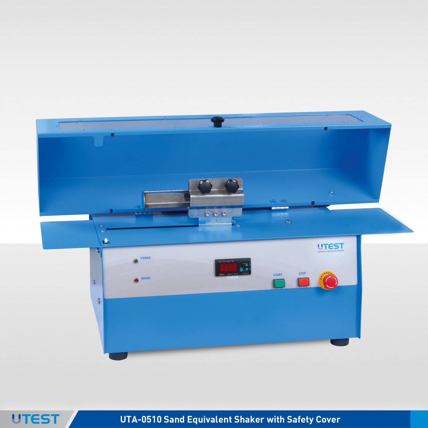
Product Code
|
UTA-0510 |
Sand Equivalent Shaker with Safety Cover |
|
Models for 220-240V 50 Hz, 1 ph. |
UTC-0510-T |
|
Models for 110-120V 60 Hz, 1 ph. |
UTC-0510-N |
|
Models for 220-240V 60 Hz, 1 ph. |
UTC-0510-K |
Standards
EN 933–8; ASTM D2419; AASHTO T176; UNI 7446
UTA-0510 Sand Equivalent Shaker is used for the uniform shaking of Sand Equivalent Measuring Cylinders, at a specified rate and stroke.
The shaker is supplied complete with a timer. The horizontal movement, cycle and shaking time can easily be adjusted on the shaker to comply with EN or ASTM standards.
|
Horizontal Movement |
200 mm ± 10 mm (EN) 203.2 mm ± 1 mm (ASTM) |
|
Cycle |
90 ± 3 / 30 sec. (EN) 175 ± 2 / min. (ASTM) |

The Sand Equivalent Shaker is supplied complete with;
- Safety Cover (conforming with CE directives)
- Timer
|
Dimensions |
350x800x440 mm |
|
Weight (approx.) |
50 kg |
|
Power |
200 W |
12. Methylene Blue Test Set
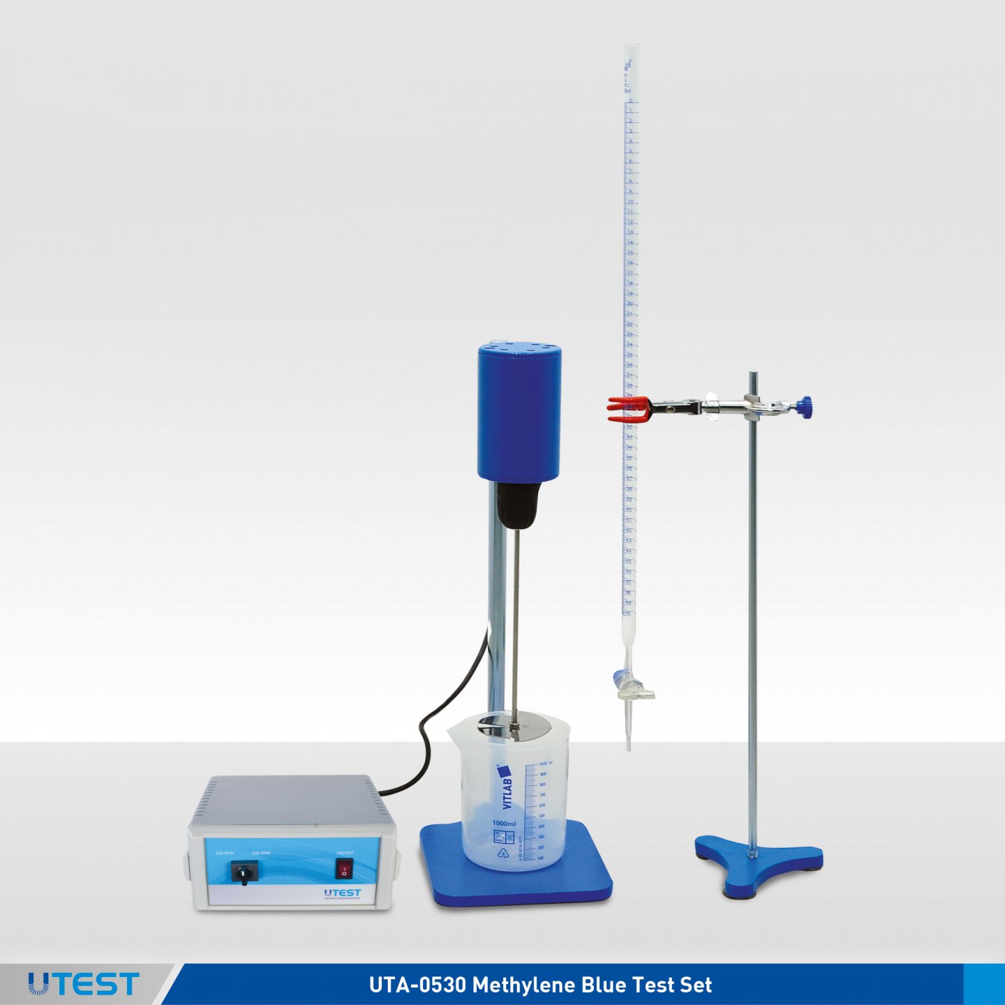
Product Code
|
UTA–0530 |
Methylene Blue Test Set, 110-230V 50-60 Hz, 1ph |
|
UTA–0531Y |
Type A Filter Paper for Methylene Blue Test, Ø:125 mm, 100 pcs/pack |
|
UTA–0532 |
Type B Filter Paper for Methylene Blue Test, Ø:125 mm, 100 pcs/pack |
|
UTA–0533 |
Type C Filter Paper for Methylene Blue Test, Ø:125 mm, 100 pcs/pack |
|
UTGC-0885Y |
Type A Methylene Blue Powder, 100 g |
|
UTGC-0886 |
Type B Methylene Blue Powder, 100 g |
|
UTGC-0880 |
Kaolinite, 500 gr |
Standards
EN 933-9; NF P94-068; UNE 83 180; UNI 8520-15
The Test Set is used for determining the Methylene Blue value of 0/2 mm fraction in fine aggregates.
UTGC-0886 Type B methylene blue powder has a dye content ≥82 %(spectrophotometrically).
Filter paper, methylene blue powder and kaolinite should be ordered separately.
|
UTA–0531Y |
Ø:125 mm |
|
UTA–0532 |
Ø:125 mm, 100 g/m2, 0.20 mm thickness, filtration speed 75s(DIN 53137), pore size 4μm. |
|
UTA–0533 |
Ø:125 mm, Quantitive, ash free max. 0,007%, 95 g/m2, thickness nominal 0.210 μm, filtration speed 340s (Herzberg), pore size 8 μm. |
Set Consists of
- High Speed Agitator Motor, 400/600 r.p.m.
- Stirring Propeller, Ø 70 mm 4 flanks
- Glass Burette, 50 ml x 0.1 ml
- Burette Holder and Stand
- Glass Rod, Ø 8x300 mm
- Plastic Beaker, 1000 ml


UTGC-0885Y UTGC-0880 UTA-0531Y UTA-0532
|
Dimensions |
510x5870x270 mm |
|
Weight (approx.) |
13 kg |
13. Los Angeles Abrasion / Fragmentation Machine


Product Code
|
UTA–0600 |
Los Angeles Abrasion Machine |
|
UTA–0601 |
Los Angeles Abrasion Machine with Soundproof Safety Cabinet |
|
UTA–0602E |
Los Angeles Abrasion Charges EN, 12 pcs. |
|
UTA–0602A |
Los Angeles Abrasion Charges ASTM/AASHTO, 12 pcs. |
|
Models for 220-240V 50 Hz, 1 ph. |
UTA-0600-T |
UTA-0601-T |
|
Models for 110-120V 60 Hz, 1 ph. |
UTA-0600-N |
UTA-0601-N |
|
Models for 220-240V 60 Hz, 1 ph. |
UTA-0600-K |
UTA-0601-K |
Standards
EN 1097-2, 12697-17, 13450; ASTM C131, C535; AASHTO T96
The Los Angeles Abrasion Machine is used for determination of the aggregates resistance to fragmentation. The machine consists of an electronic control unit and a rolled steel drum having an inside diameter of 711 mm and internal length of 508 mm. The drum is rotated at a speed of 31-33 r.p.m. The internal shelf provided with the machine confirms to ASTM, AASHTO and EN standards. The machine is equipped with an automatic counter, when the preset revolution count is reached, the machine will stop automatically. The drum is equipped with an interlock device which allows the operator to lock the drum into position for easy loading/unloading of the sample.
A steel tray is supplied with the machine for easy discharge of specimen and abrasive charges.
The standard model can be supplied with a safety/noise reduction cabinet. The cabinet is lined internally with soundproofing material to reduce sound level conforming to CE directives. The cabinet must be ordered with the Los Angeles machine if required, as the electronic control unit will be installed on the safety cabinet at the time of manufacture. The cabinet is equipped with an electric safety device which automatically stops the rotation of the drum when the door is opened, conforming to CE directives.
- Abrasion balls and 1.6 mm, 10mm, 11.2mm (or 12.5mm), 14 mm sieves and guard sieves (2mm, 4mm and 6mm) acc. to EN standard
- Abrasion balls, 1.7 mm( No.12) sieve and other sieves which chance depending the grain size acc. to ASTM and AASHTO standards, should be ordered separately.
The Los Angeles Abrasion Machine is supplied complete with;
- Steel Tray

Control Panel Drum Position Lock with Safety Switch
|
|
UTA-0600 |
UTA-0601 |
|
Dimensions |
850x900x950 mm |
1060x1100x1210 mm |
|
Weight (approx.) |
361 kg |
528 kg |
|
Power |
800 W |
800 W |
14. Wide Wheel Abrasion Testing Machine
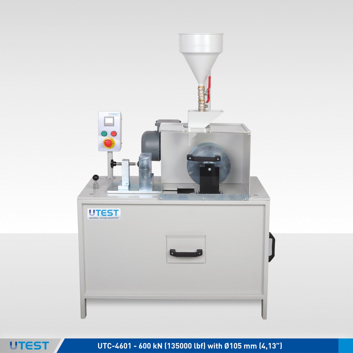
Product Code
|
UTA-0610 |
Wide Wheel Abrasion Testing Machine |
|
UTA-0611 |
Abrasive Corundum Sand 25 kg for UTA-0610 and UTA-0613 |
|
UTA-0612 |
Calibration Marble for UTA-0610 |
|
UTA-0613 |
Narrow Wheel Abrasion Testing Machine |
|
UTA-0614 |
Mould, EN 12808-2, Polyethylene, 100 ±1x100 ±1x10 ±1 mm, for UTA-0613 |
|
Models for 220-240V 50 Hz, 1 ph. |
UTC-0610-T |
UTC-0613-T |
|
Models for 110-120V 60 Hz, 1 ph. |
UTC-0610-N |
UTC-0613-N |
|
Models for 220-240V 60 Hz, 1 ph. |
UTC-0610-K |
UTC-0613-K |
Standards
Wide Wheel : EN 1338, 1339, 1340, 1341, 1342, 13748-1,13748-2, 14157
Narrow Wheel: 10545-6, 12808-2
UTA-0610 Abrasion Testing Machine is designed for determining the resistance to abrasion/wear of natural stones and concrete products used for paving. The abrasion wheel is 70 mm thick and rotates at a speed of 75 rpm. The machine is equipped with a digital counter which stops the machine at the end of a preset number of revolutions.
UTA-0613 Narrow Wheel Abrasion Testing Machine is designed for determining the resistance to abrasion of unglazed tiles, grouts used for tiles and clay pavers. The abrasion wheel is 10 mm thick. Abrasive corundum sand, calibration marble (boloneisse) and mould (for EN 12808-2) should be ordered separately.
|
Dimensions |
450x930x1100 mm |
|
Weigh (approx.) |
140 kg |
|
Power |
370 W |
15. Abrasion Testing Machine According to Böhme
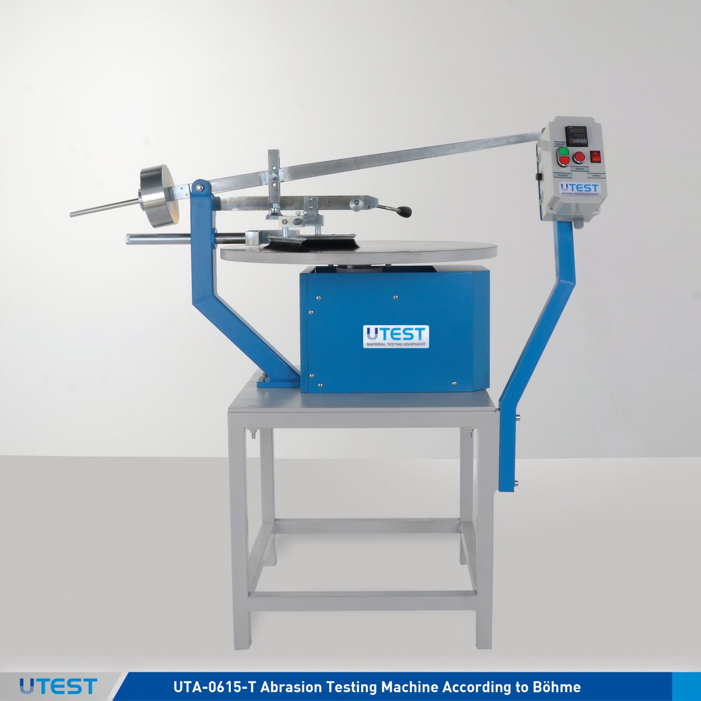
Product Code
|
UTA-0615-T |
Abrasion Testing Machine According to Böhme, 220-240 V 50 Hz, 1 ph (60 Hz version is available upon request) |
|
UTA-0616 |
Abrasive Sand, 50 kg pack for UTA-0615 |
Standards
EN 1338, 1339, 1340
UTA-0615 the Abrasion Testing Machine according to Böhme is used for determining the abrasion resistance of concrete and natural stone products used for internal or external paving.
The machine consists of a grinding wheel of approx. 750 mm diameter, a removable testing weight of 30 kg and a clamping device for the sample. The machine is equipped with an adjustable counter (30 ± 1 r.p.m.) and an automatic cut-off system which stops the machine after 22 rotations.
UTA-0616 Abrasive Sand should be ordered separately.
|
Dimensions |
810x1460x1270 mm |
|
Weigh (approx.) |
210 kg |
|
Power |
750 W |
16. Micro-Deval Apparatus EN
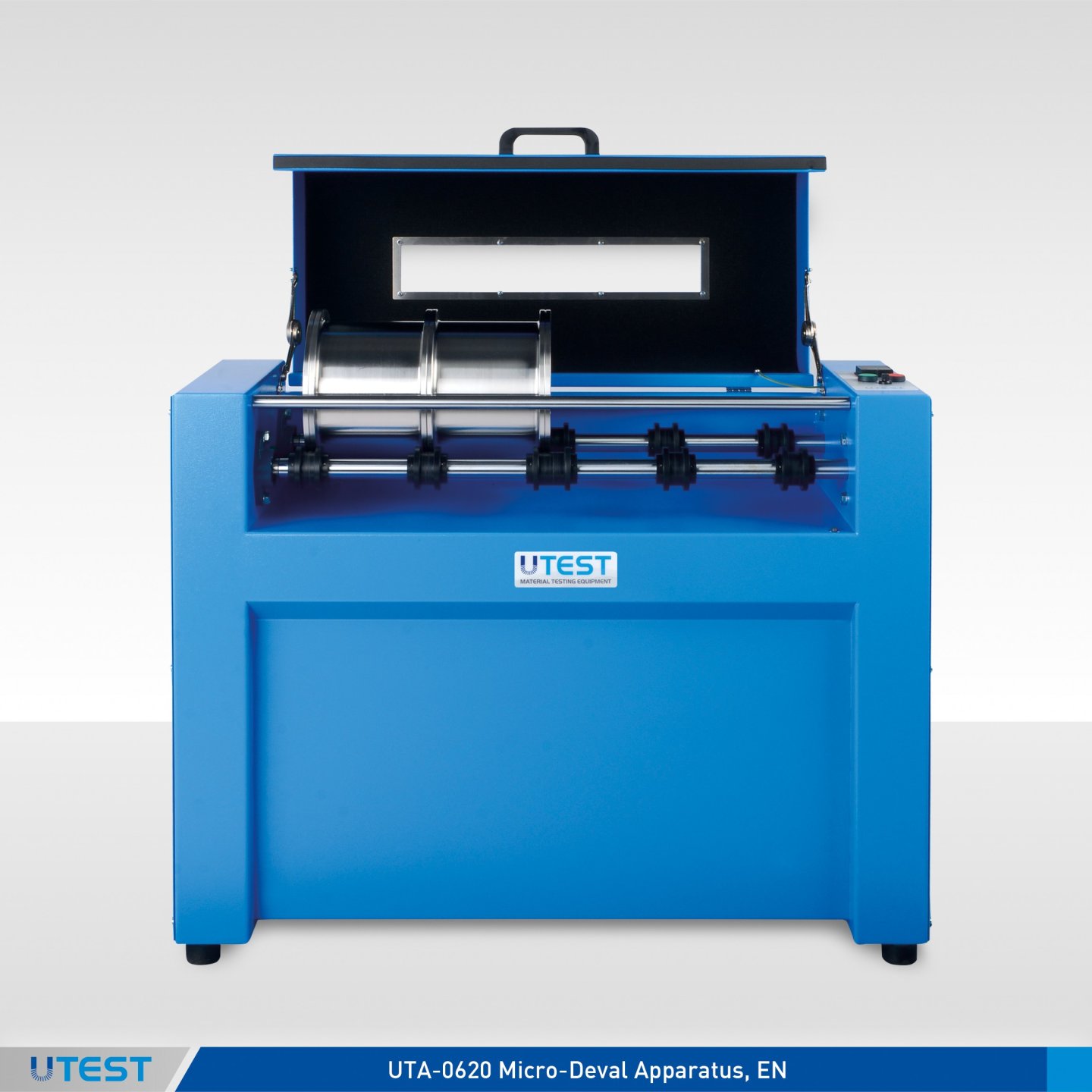
Product Code
|
UTA-0620E |
Micro-Deval Apparatus, EN |
|
UTA-0621E |
Stainless Steel Drum, EN, Ø 200x154 mm ID for UTA-0620E |
|
UTA-0622E |
Stainless Steel Drum EN, Ø 200x400 mm ID for UTA-0620E |
|
UTA-0623E |
Micro-Deval Abrasion Charges, Stainless Steel, EN, Ø10 mm 20 kg Pack |
|
UTA-0624B |
Micro-Deval Abrasion Ball Set, BS, (3 pcs. balls) |
|
UTA-0626 |
Abrasive Steel Charges Collector |
|
Models for 220-240V 50 Hz, 1 ph. |
UTC-0620E-T |
|
Models for 220-240V 60 Hz, 1 ph. |
UTC-0620E-K |
Standards
EN 1097-1, 13450; BS 7533-3
The Micro Deval Testing Machine is used to determine the resistance to wear of aggregates. Automatic digital counter allows machine to stop automatically at the preset number of revolutions. The machine has electronic control unit with digital display,
Stainless steel drums are rotating at a speed of 100 ± 5 r.p.m.
The machine can accept up to 4 pcs. Ø 200x154 mm drums or 1 pcs. Ø 200x400 mm drums.
Stainless steel abrasion charges (UTA-0623) and Ø 200x154 mm steel drums (UTA-0621E) should be ordered separately.
Additionally, Ø200x400 mm stainless steel drum/s (UTA-0622E), abrasive steel charges collector (UTA-0626), BS Micro-Deval Abrasion Ball Set (UTA-0624B), the sieves (1,6 mm, 8 mm, 10 mm, 11,2 mm or 12,5 mm and 14,0 mm) the sieves for railway ballast (1,6 mm, 8 mm, 31.5 mm, 40.0 mm and 50.0 mm) should be ordered separately.

|
Dimensions |
450x1260x980 mm |
|
Weight (approx.) |
95 kg |
|
Power |
550 W |
17. Micro-Deval Apparatus ASTM
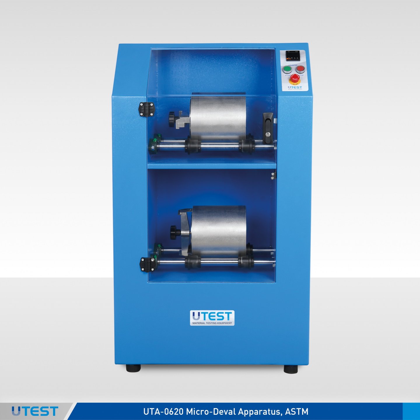
Product Code
|
UTA-0620A |
Micro-Deval Apparatus, ASTM, 220-240 V 50 Hz |
|
UTA-0621A |
Stainless Steel Jar, ASTM, for UTA-0620A |
|
UTA-0623A |
Micro-Deval Abrasion Charges, ASTM, Ø9,5 mm, 2 pcs. of 6 kg Packed |
|
UTA-0626 |
Abrasive Steel Charges Collector |
|
Models for 220-240V 50 Hz, 1 ph. |
UTC-0620A-T |
|
Models for 110-120V 60 Hz, 1 ph. |
UTC-0620A-N |
|
Models for 220-240V 60 Hz, 1 ph. |
UTC-0620A-K |
Standards
ASTM D6928, D7428; AASHTO T327
The Micro Deval Testing Machine is used to determine the resistance to wear of aggregates. The machine consists of a steel frame, two stainless steel jar stainless steel spheres (2 pcs) and an automatic digital counter which allows machine to stop automatically at the preset number of revolutions.
Stainless steel jars are rotating at a speed of 100 ± 5 r.p.m.
Sieves (19.0 mm,16.0 mm, 12.5 mm, 9.5 mm, 6.3 mm, 4.75 mm and 1.18mm) and abrasive steel charges collector (UTA-0626) should be ordered separately.

UTA-0620A Micro-Deval Apparatus is supplied complete with;
- Stainless Steel Jar, ASTM, 2 pcs.
- Abrasion Charges, ASTM, Ø9,5 mm, 2 pcs. of 6 kg packed
|
Dimensions |
385x680x1180 mm |
|
Weight (approx.) |
105 kg |
|
Power |
550 W |
18. Nordic Abrasion Machine
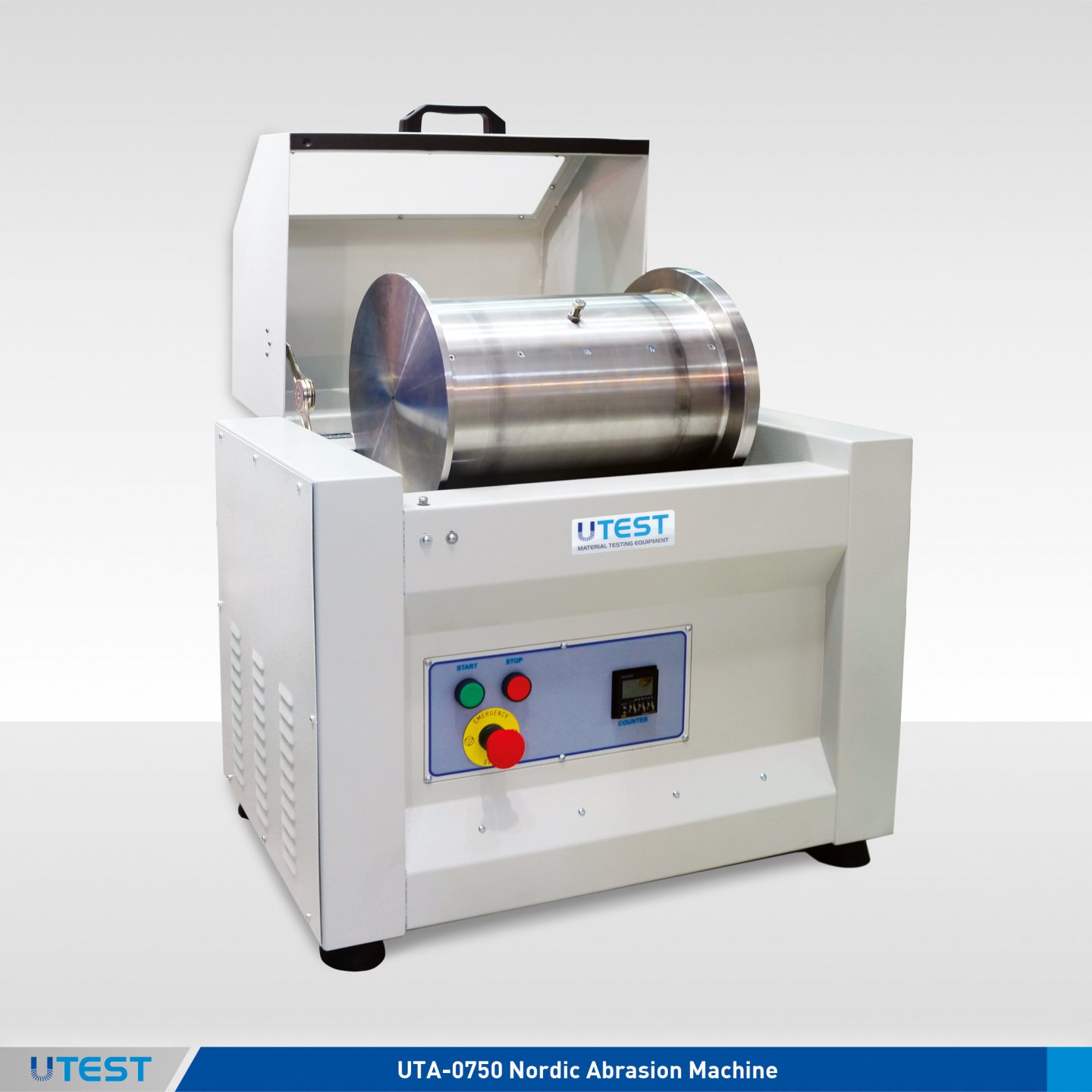
Product Code
|
UTA-0750 |
Nordic Abrasion Machine |
|
UTA-0751 |
Steel Balls, Ø 15 mm dia, Stainless, 7 kg |
|
UTA-0752 |
Steel Balls, Ø 11.1 mm dia, Stainless, 3,5 kg |
|
UTA-0753 |
Stainless Steel Drum for UTA-0750 |
|
UTA-0626 |
Abrasive Steel Charges Collector |
|
Models for 220-240V 50-60 Hz, 1 ph. |
UTA-0750 |
|
Models for 110-120V 60 Hz, 1 ph. |
UTA-0750-N |
Standards
EN 1097-9; UNI 8520-13-16
UTA-0750 Nordic Abrasion Machine has been developed for testing the resistance of aggregates to wear by abrasion from studded tyres. The test is performed on natural or artificial stones and aggregates between 11.2 mm and 16.0 mm.
The test consists of a rotating aggregate in a drum containing steel abrasive balls and water. The machine consists of an electronic control unit and a rolled stainless steel drum having an internal diameter of 206.5 mm, internal length of 335 mm and thickness of 6 mm. The drum is rotated at a speed of 90 ± 3 r.p.m. 3 wings are installed inside of the drum to allow the balls and aggregates to be mixed properly.
The abrasion loss rate of aggregates is calculated after the specified number of revolutions stated in the relevant standard.
Sieves (2 mm, 11.2 mm, 14.0 mm and 16.0 mm), abrasive steel charges collector(UTA-0626) and also for aggregates between 8mm and 11,2 mm (Sieves 2 mm, 8 mm, 10 mm, 11.2 mm and Ø 11.1 mm steel balls UTA-0752) should be ordered separately.
The Nordic Abrasion Machine is supplied complete with;
- Stainless Steel Drum, 1 pcs.
- Steel Balls, Ø 15 mm, 7 kg
|
Dimensions |
450x700x750 mm |
|
Weight (approx.) |
70 kg |
|
Power |
600 W |
19. Aggregate Crushing Value (ACV) Sets
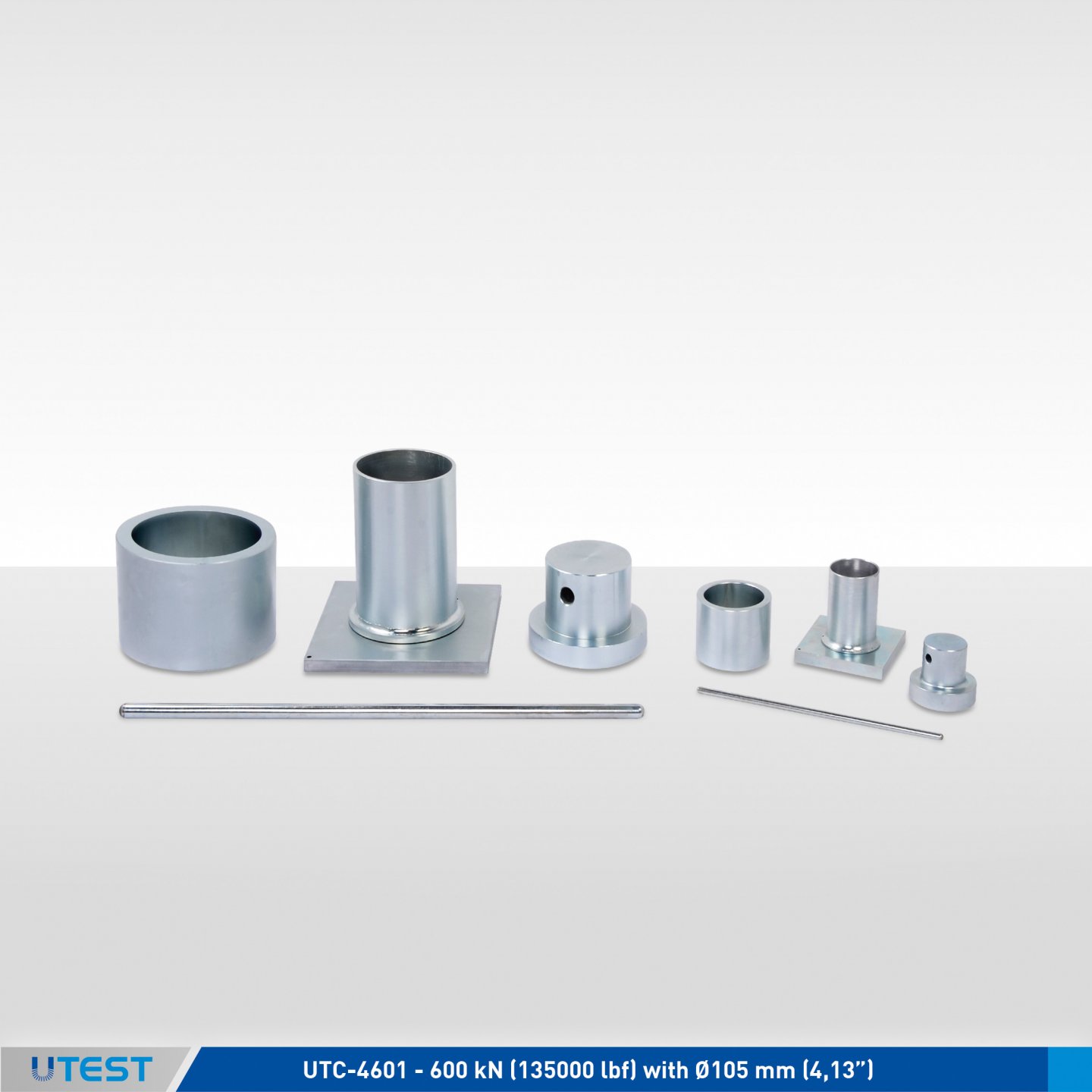
Product Code
|
UTA-0630 |
Aggregate Crushing Value (ACV) Set Ø 150 mm BS |
|
UTA-0631 |
Aggregate Crushing Value Cylinder Ø 150 mm for UTA-630 |
|
UTA-0632 |
Aggregate Crushing Value Base Plate for UTA-630 |
|
UTA-0633 |
Aggregate Crushing Value Plunger for UTA-630 |
|
UTA-0634 |
Aggregate Crushing Value Cylindrical Measure for UTA-630 |
|
UTC-0408 |
Tamping Rod Ø 16x600 mm |
|
UTA-0640 |
Aggregate Crushing Value (ACV) Set Ø 75 mm BS |
|
UTA-0641 |
Aggregate Crushing Value Cylinder Ø 75 mm for UTA-640 |
|
UTA-0642 |
Aggregate Crushing Value Base Plate for UTA-640 |
|
UTA-0643 |
Aggregate Crushing Value Plunger for UTA-640 |
|
UTA-0644 |
Aggregate Crushing Value Cylindrical Measure for UTA-640 |
|
UTA-0645 |
Tamping Rod Ø 8x300 mm |
Standards
BS 812:110, 812-11
The Aggregate Crushing Value (ACV) Test Set provides a relative measure of the resistance of an aggregate to crushing under a gradually applied compressive load. Each set consists of steel cylinder, plunger, base plate, cylindrical measure and tamping rod. All parts of the apparatus are powder coated or galvanized steel, heat treated and ground before manufacturing to make it durable and reliable. For aggregates smaller than 10 mm, a 75 mm diameter cylinder and associated equipment is available.
UTA-0630 and UTA-0640 Test Sets are also used for the Ten Percent Fines Value (TFV) of aggregates according to BS 812:111.
The Aggregate Crushing Value (ACV) Set is supplied complete with;
- Cylinder
- Base Plate
- Plunger
- Cylindrical Measure
- Tamping Rod
|
|
UTA-0630 |
UTA-0640 |
|
Dimensions |
220x220x310 mm |
110x110x150 mm |
|
Weight (approx.) |
29 kg |
5 kg |
20. Aggregate Impact Value (AIV) Test Machine

Product Code
|
UTA-0650 |
Aggregate Impact Value (AIV) Testing Apparatus |
Standards
BS 812:112
The Aggregate Impact Value Testing Apparatus, meets with BS 812, it is robustly designed to determine the Aggregate Impact Value (AIV) of aggregates which provides a relative measure of the resistance of an aggregate to sudden shock or impact. The counter fitted to the machine automatically records the number of blows delivered to the sample, manufactured from heavy duty plated steel to resist corrosion.
The Aggregate Impact Value (AIV) Apparatus is supplied complete with;
- Cylindrical Measure, Ø 75 mm,
- Steel Tamping Rod, Ø 16x600 mm
|
Dimensions |
310x310x840 mm |
|
Weight (approx.) |
54 kg |
21. Bulk Density Measures
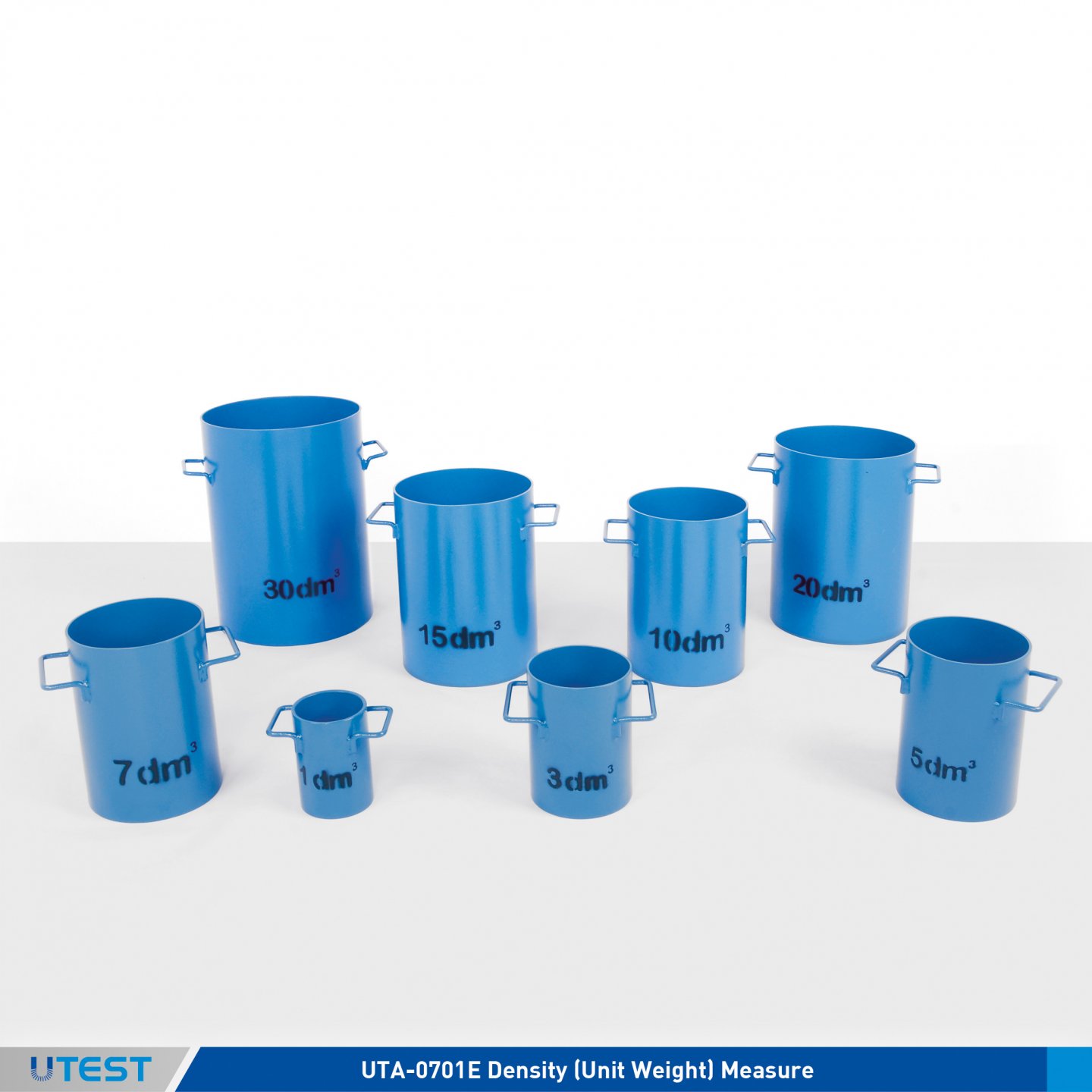
Product Code
|
UTA-0701E |
Density (Unit Weight) Measure 1 lt. EN |
|
UTC-0603E |
Density (Unit Weight) Measure 3 lt. EN |
|
UTA-0705E |
Density (Unit Weight) Measure 5 lt. EN |
|
UTC-0607E |
Density (Unit Weight) Measure 7 lt. EN |
|
UTC-0610E |
Density (Unit Weight) Measure 10 lt. EN |
|
UTC-0615E |
Density (Unit Weight) Measure 15 lt. EN |
|
UTA-0720E |
Density (Unit Weight) Measure 20 lt. EN |
|
UTC-0630E |
Density (Unit Weight) Measure 30 lt. EN |
Standards
EN 1097–3, 12350-6
Density (Unit Weight) Measures are used to determine the weight per cubic meter of bulk or compacted agregates.
The Density Measures are manufactured from heavy duty steel complying with the related standard. Available in 1, 3, 5, 7, 10, 15, 20 and 30 lt capacity models to comply with the relevant standards. The measures are coated against corrosion.
|
|
Dimensions |
Weight (approx.) |
|
UTA-0701E |
170x100x150 mm |
2.8 kg |
|
UTC-0603E |
150x250x200 mm |
3.7 kg |
|
UTA-0705E |
170x250x250 mm |
5 kg |
|
UTC-0607E |
210x300x240 mm |
6.3 kg |
|
UTC-0610E |
210x300x310 mm |
7.7 kg |
|
UTC-0615E |
250x330x340 mm |
10 kg |
|
UTA-0720E |
370x360x370 mm |
12 kg |
|
UTC-0630E |
300x380x440 mm |
20 kg |
22. Specific Gravity Frame
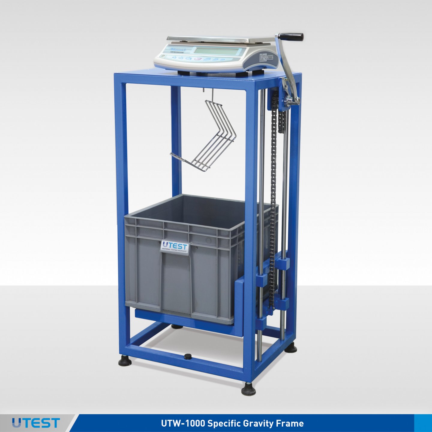
Product Code
|
UTW-1000 |
Specific Gravity Frame |
|
UTW-1003 |
Plastic Water Tank |
|
UTW-1005 |
Cradle for Hardened Concrete Specimens |
|
UTW-1008 |
Density Basket, 120 mm dia x 160 mm deep, 3.35 mm stainless steel mesh |
|
UTW-1010 |
Density Basket Ø 200 mm x 200 mm 3.35 mm stainless steel mesh |
|
UTW-1012 |
Density Basket, 250 mm dia x 250 mm 3.35 mm (No.6) stainless steel mesh |
|
UTW-1015 |
Density Basket, 200 mm dia x 180 mm 2.00 mm (No:10) stainless steel mesh |
Standards
EN 1097-6, 12390-7; ASTM C127; AASHTO T85; BS 812-2
The UTW-1000 Specific gravity framework is used to find the volume occupied by the aggregate in various mixtures containing coarse aggregates, with the aid of a scale and a wire basket.It is also used to find the volume of irregularly shaped natural stone and similar materials.
The lower part of the frame incorporates a moving platform, which carries the water tank allowing the test specimens to be weighed in both air and water.
The frame can be used with any type of electronic balance fitted with under-bench weighing facility
Balance, cradle and density basket should be ordered separately.
The Specific Gravity Frame is supplied complete with;
- A water tank

UTW-1005 UTW-1010 UTW-1003
|
Dimensions |
400x560x1000 mm |
|
Weight (approx.) |
26 kg |
23. Pyknometer (Glass Jar Type)
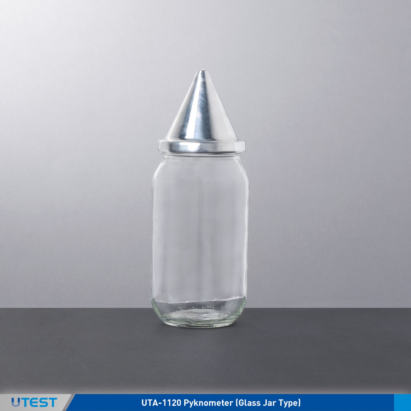
Product Code
|
UTA-1120 |
Pyknometer (Glass Jar Type) |
Standards
BS 812:2, 1377-2; ASTM C128, D854; AASHTO T84
The Pyknometer is used for the determination of the relative density and water absorption for aggregates of 10 mm nominal size and smaller.
|
Dimensions |
Ø100x200 mm |
|
Weight (approx.) |
0,50 kg |
24. Pyknometers (Bottle Type)
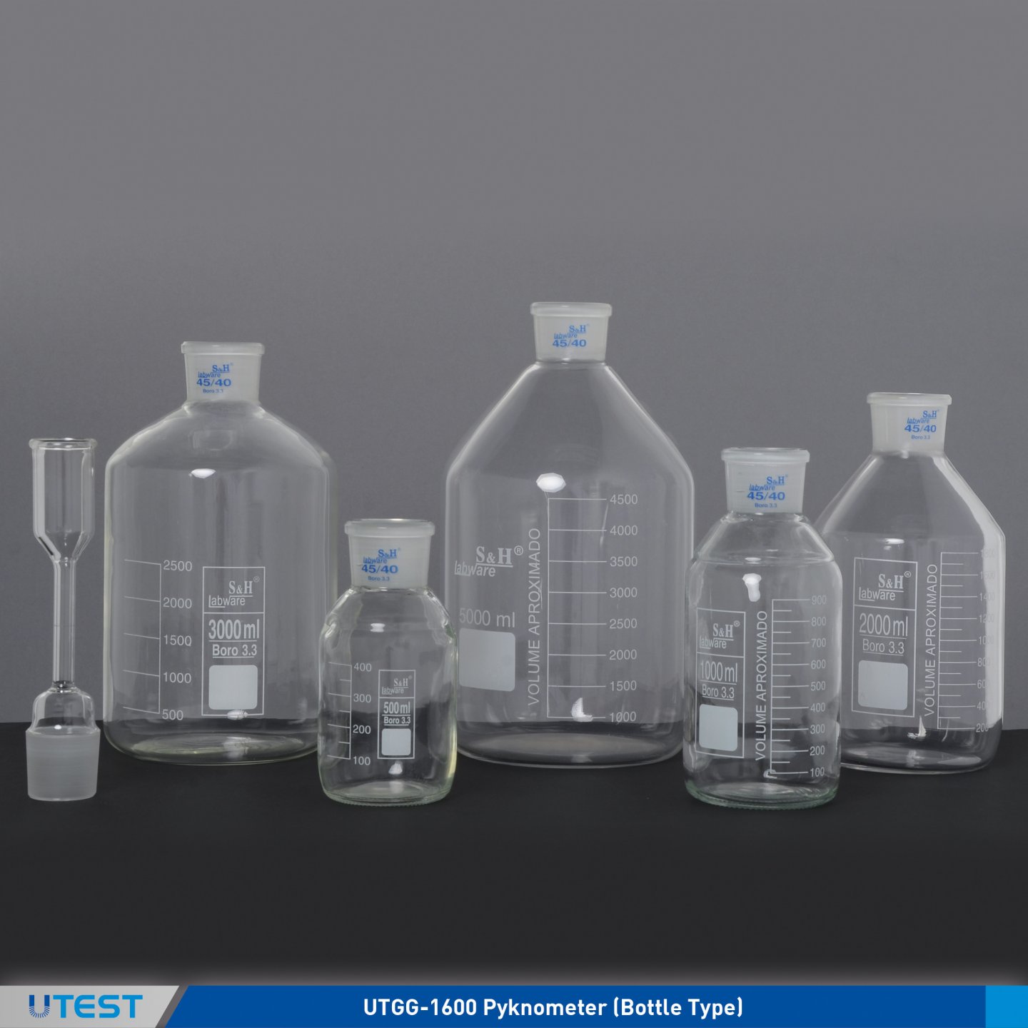
Product Code
|
UTGG-1600 |
Pyknometer (Bottle Type) 250 ml |
|
UTGG-1605 |
Pyknometer (Bottle Type) 500 ml |
|
UTGG-1610 |
Pyknometer (Bottle Type) 1000 ml |
|
UTGG-1615 |
Pyknometer (Bottle Type) 2000 ml |
|
UTGG-1620 |
Pyknometer (Bottle Type) 3000 ml |
|
UTGG-1625 |
Pyknometer (Bottle Type) 5000 ml |
|
UTGG-1630 |
Double Edged and Capillary Tubed Funnel |
Standards
EN 1097-6
Bottle Type Pyknometers are used to determine the specific gravity of aggregates. 250 ml, 500 ml, 1000 ml, 2000 ml, 3000 ml and 5000 ml.
The Bottle Type Pyknometer is supplied complete with;
- Double Edged and Capillary Tubed Funnel
|
|
Dimensions |
Weight (approx.) |
|
UTGG-1600 |
Ø60x330 mm |
0,30 kg |
|
UTGG-1605 |
Ø80x360 mm |
0,50 kg |
|
UTGG-1610 |
Ø100x410 mm |
0,60 kg |
|
UTGG-1615 |
Ø130x450 mm |
0,90 kg |
|
UTGG-1620 |
Ø160x480 mm |
1 kg |
|
UTGG-1625 |
Ø180x510 mm |
2 kg |
|
UTGG-1630 |
Ø40x230 mm |
0,10 kg |
25. Sand Absorption (Abraham Cone) Sets

Product Code
|
UTA-0755 |
Sand Absorption (Abraham Cone) Set |
|
UTA-0756 |
Sand Absorption (Abraham) Cone |
|
UTA-0757 |
Tamping Rod Ø25 mm |
Standards
EN 1097-6; BS 812-2; UNI 8520-13-16; ASTM C128; NLT 154; DIN 12039
The Sand Absorption Abraham Cone Set is used in determining the specific gravity and water absorption of fine aggregates smaller than 10 mm. The apparatus is manufactured from plated steel for protection against corrosion.
The cone dimensions are:upper diameter of 40 mm, lower diameter of 90 mm and 75 mm height, and the tamping rod has a 25 mm base diameter and approx. 340 g in weight.
The abrasion loss rate of aggregates is calculated after the specified number of revolutions stated in the relevant standard.
|
Dimensions |
90x90x180 mm |
|
Weight (approx.) |
0,5 kg |
26. Microlance Instant Moisture And Temperature Tester
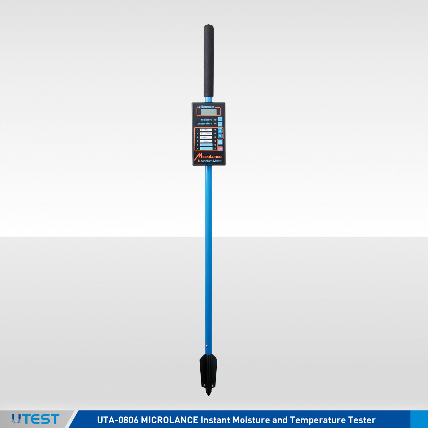
Product Code
|
UTA-0806 |
Microlance Instant Moisture and Temperature Tester |
UTA-0806 MICROLANCE Instant Moisture and Temperature Tester is used for the instant on-site determination of moisture and temperature of sands, aggregates, building materials, minerals and mixes from small quantities to hundreds of tons.
The instrument is reliable and easy to use, taking moisture readings up to 1 meter depth by simply inserting the lance into the test material. Instant readings are monitored on the digital display and the built-in computer allows the user to monitor a wide range of materials and water contents.
The UTA-0806 Microlance is supplied with standard calibration values for sands and aggregates but it can also be calibrated for different material or mixture with the Autocal functionality. The unit is supplied complete with a calibration certificate.
|
|
Range |
Resolution |
Accuracy |
|
Moisture |
0 to 25 % |
0.1 % |
better than 0.5 % |
|
Tempature |
-20 to 60°C |
0.1 °C |
better than 0.5 °C |
- Moisture measurement with temperature compensated electric field
- Temperature measurement according to BS 1904 and DIN 751
- Platinum resistance detector
- Works with 4 x 1.5 V AA cells (or equivalent)

|
Dimensions |
100x100x1200 mm |
|
Weight (approx.) |
2 kg |
27. Skid Resistance and Friction Tester
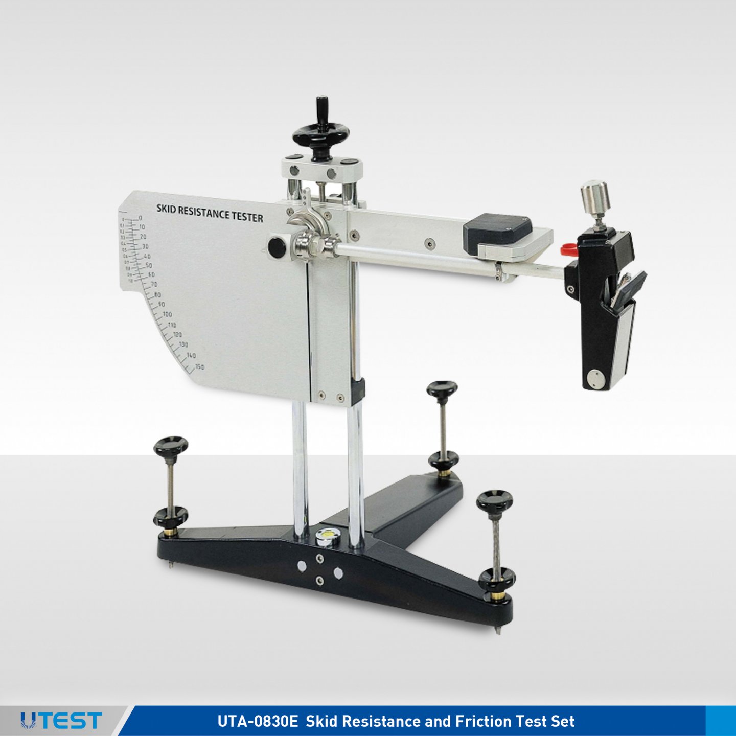
Product Code
|
UTA-0830E |
Skid Resistance and Friction Test Set (Skid Tester), EN 1097-8 |
|
UTA-0830A |
Skid Resistance and Friction Test Set (Skid Tester), ASTM E303 |
|
UTA-0832-TRL |
Mounted Rubber Slider, TRL rubber, 32 mm width for PSV test (PSV laboratory). Complete with conformity certificate. for UTA-0830 |
|
UTA-0833-TRL |
Mounted Rubber Slider,TRL rubber, 76 mm width for site use, complete with conformity certificate, for UTA-0830 |
|
UTA-0832-4S |
Mounted Rubber Slider, 4S rubber, 32 mm width |
|
UTA-0833-4S |
Mounted Rubber Slider, 4S rubber, 76 mm width |
|
UTA-0834 |
Metal Base Plate for Polished Stone Value Specimen Clamping, for UTA-0830 |
|
UTA-0835 |
Metal Base Plate for Surface Friction Properties for Natural Stones (EN 1341, EN 1342) and Concrete Paving, Blocks (EN 1338) |
Standards
EN 1097-8, 1338, 1341, 1342, 13036-4; ASTM E303
The Skid Resistance and Friction Testers are used for the measurement of surface friction properties. The apparatus is suitable for both site and laboratory applications and for Polished Stone Value tests using curved specimens from accelerated polishing tests with the Acelereted Polishing Machine (UTA-0810). UTA-0830E can also be used for testing Paving Stones (EN 1341, EN 1342) and Paving Blocks (EN 1338).
The apparatus consist of an adjustable pendulum arm, and a spring loaded rubber slider (see spare parts) mounted on the end of the arm.
Rubber sliders (UTA-0832-TRL, UTA-08332-TRL, UTA-0832-4S and UTA-0832-4S) should be ordered separately.
The Skid Resistance and Friction Testers are supplied complete with;
- Additional Scale, for Test on Polished Stone Value Specimens
- Thermometer, 0 to +220°C for Surface Temperature Measurement
- Washing Bottle, for Surface Wetting - 1 L
- Tool Set with case for machine assembly
- Rule for Sliding Length Verification
- Traceability Certificate of Conforming to EN 1097-8 or ASTM E303
- Carrying Case
|
Dimensions |
790x760x320 mm (case) |
|
Weight (approx.) |
34 kg |
28. Polished Stone Value / Resistance to Polishing
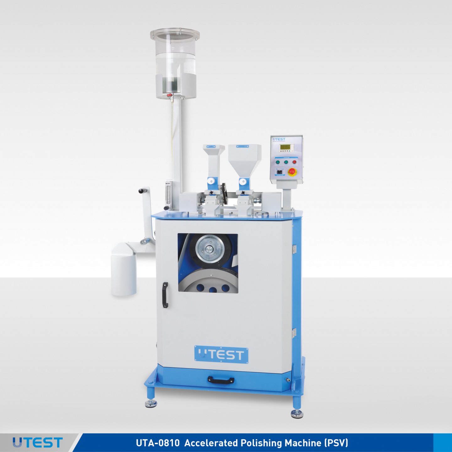
Product Code
|
UTA-0810 |
Accelerated Polishing Machine (PSV) |
|
UTA-0811 |
Specimen Mould with a Cover, for UTA-0810 |
|
UTA-0812 |
Corn Emery 5 kg, for UTA-0810 |
|
UTA-0813 |
Flour Emery 5 kg, for UTA-0810 |
|
Models for 220-240V 50-60 Hz, 1 ph. |
UTA-0810 |
|
Models for 110-120V 60 Hz, 1 ph. |
UTA-0810-N |
Standards
EN 1097-8; BS 812:114:1989
Accelerated Polishing Machine (PSV) is used to simulate the polishing action of vehicle tyres on a road surface, for coarse aggregate which is going to be used as asphalt road surface covers.
Abrasive Corn Emery is fed to the point of contact of the wheel on the test surface for 3 hours, followed by feeding Emery Flour to polish the surface being tested for a further 3 hours. Subsequent skid tests are carried out on the test samples using suitable portable skid test equipment.
UTA-0812 Corn Emery, UTA-0813 Flour Emery, additional Specimen Mould with a Cover (UTA-0811) should be ordered separately.
The Accelerated Polishing Machine is supplied complete with;
- Specimen Mould with a Cover ( 1 pcs.)
- Container - 2 pcs. For setting the mass ( one forflour and one for corn emery)
- Allen Key Set
- Rubber Tired Wheels (2 pcs.)
|
Road Wheel Speed |
315 to 325 r.p.m |
|
Dimensions |
480x950x1850 mm |
|
Weight (approx.) |
235 kg |
|
Power |
850 W |
29. Magnesium Sulphate / Sodium Sulphate Test Water Bath
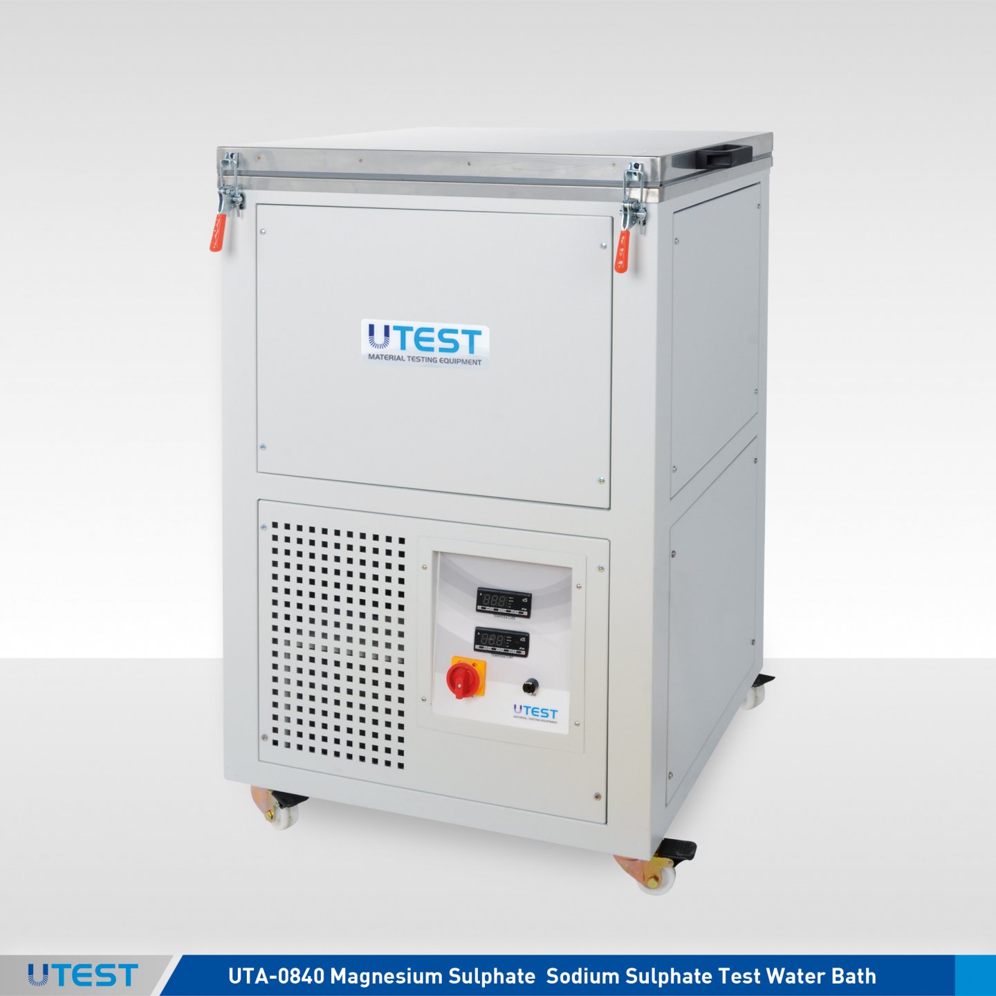
Product Code
|
UTA-0840 |
Magnesium Sulphate/Sodium Sulphate Test Water Bath |
|
UTW-1008 |
Density Basket, Ø120 x 160 mm deep, 3,35 mm mesh, EN/ASTM |
|
UTGH-1460 |
Container for Density Basket, Ø160 x 200 mm deep, Aluminium, for UTW-1008, EN/ASTM |
|
UTW-1017 |
Density Basket, Ø230 x 260 mm deep, 4 mm stainless steel mesh, EN |
|
UTGH-1465 |
Container for Density Basket Ø270 x 300 mm deep, Aluminium, for UTW-1017, EN |
|
UTGG-2415 |
Hydrometer 1100-1200 g/ml, ASTM |
|
UTGG-2420 |
Hydrometer 1200-1300 g/ml, EN/ASTM |
|
UTGC-0850 |
Sodium Sulphate, 1 kg, ASTM |
|
UTGC-0915 |
Magnesium Sulphate, 1 kg, EN/ASTM |
|
Models for 220-240 V 50-60 Hz, 1ph. |
UTA-0840 |
|
Models for 110-120V 60 Hz, 1ph. |
UTA-0840-N |
Standards
EN 1367-2, 13450; ASTM C88; UNI 8520-10; UNE 7136
Magnesium Sulphate and Sodium Sulphate Tests are used for determining the soundness of aggregates when subjected toweathering action such as freezing and thawing in concrete or other applications. Only the specific products are listed above for the test. It should be noted that other equipment like ovens, sieves, balances etc. are also required to perform these tests.
Sodium Sulphate can be used instead of Magnesium Sulphate according to the ASTM standard. UTGG-2415 Hydrometer 1100-1200 g/ml is required for the test with Sodium Sulphate Test.
The temperature of test solution is automaticly adjusted to required temperature with a microprocessor type sensor placed in the water bath. The second sensor can be placed in the lever lid containers or stainless steel immersion container by user.The temperature data of water bath and the temperature test solution are displayed in real time on digital screen with 0.1°C resolution.
Homogenous temperature distribution can be obtain with water circulation pump that makes feedback.
Magnesium Sulfate / Sodium Sulfate Test Water Bath has (20±2) 0C accuracy and can be used as general purpose water bath that temperature is between 15-60 °C temperature
Supplied complete with the immersion container with the cover.
Density Baskets, Container for Density Basket, Hydrometer, Magnesium or Sodium Sulphate should be ordered seperately.

UTW-1008 UTGH-1460
|
|
Dimensions |
Weight |
|
UTA-0840 |
550x750x950 mm |
75 kg |
|
Chamber of Bath |
560x460x500 mm |
-- |
|
UTW-1008 |
Ø160x200 mm |
0,20 kg |
|
UTGH-1460 |
Ø160x200 mm |
0,50 kg |
|
UTW-1017 |
Ø230x260 mm |
0,80 kg |
|
UTGH-1465 |
Ø280x300 mm |
1 kg |
|
UTGG-2415 |
20x20x330 mm |
0,10 kg |
|
UTGG-2420 |
20x20x330 mm |
0,10 kg |
|
Immersion Container |
330x330x330 mm |
4 kg |
30. Freezing and Thawing Chamber for Slab Tests
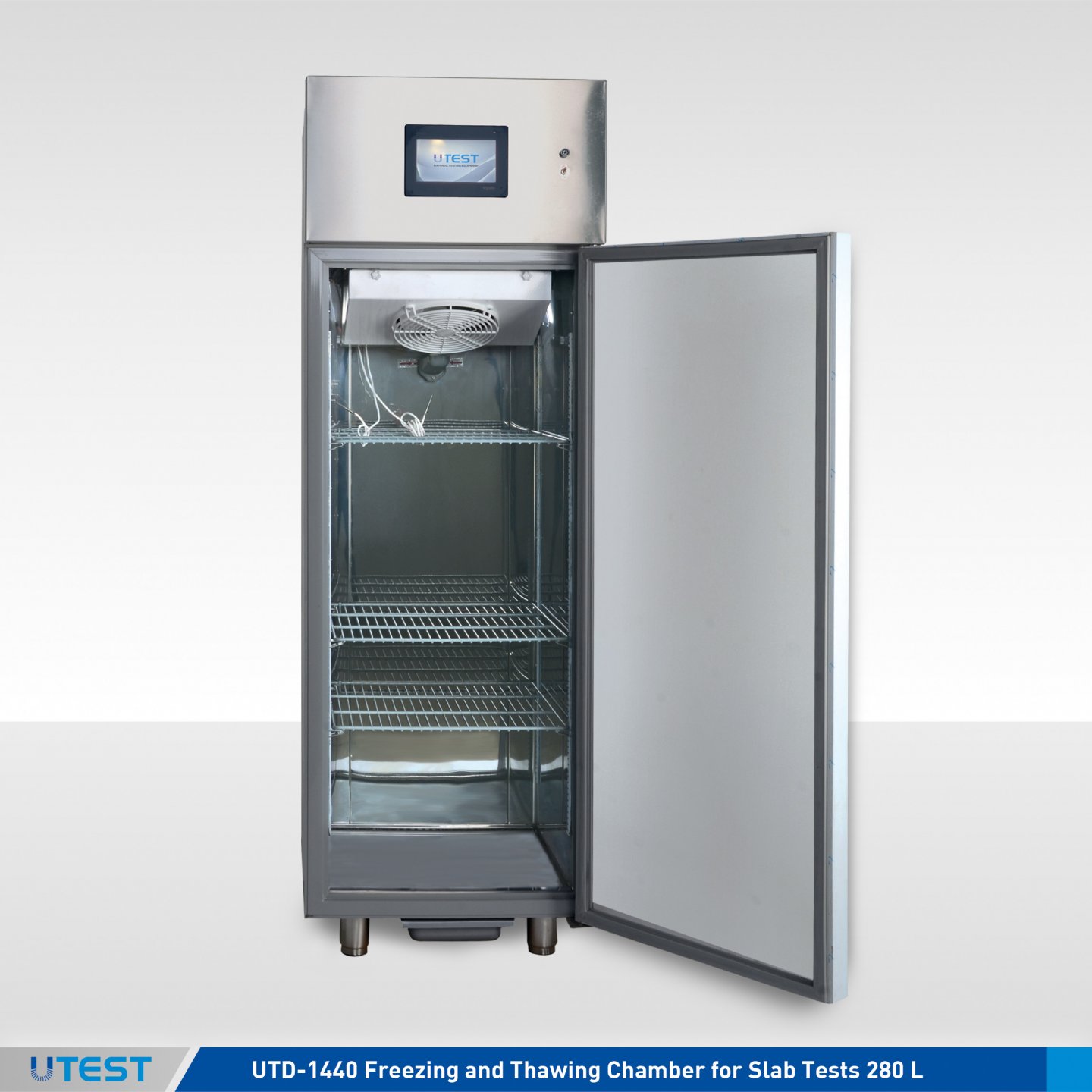
Product Code
|
UTD-1440 |
Freezing and Thawing Chamber for Slab Tests 280 L |
|
UTD-1442 |
Freezing and Thawing Chamber for Slab Tests 500 L |
|
Models for 220-240 V 50-60 Hz, 1ph. |
UTD-1440 |
UTD-1442 |
|
Models for 110-120 V 60Hz, 1ph. |
- - - |
UTD-1442-N |
Standards
EN 1338, 1339, 1340, 1367-6, 13748-2; CEN/TS 12390-9 (Slab Test)
UTD-1440 and UTS-1442 are used for the determination of resistance to freezing and thawing of the construction materials.
The chambers are equipped with a user defined program including up to 16 steps. Time can be adjusted to 999 minutes for each step of the program. The temperature range of the cabinet is -30°C to +65°C.
The temperature is controlled by a sensor which can be immersed either into the sample, or into the water which the sample is placed into or into the salty water solution placed on the sample before starting the test. The calibration of the sensor is carried out using the user friendly menu.
The distribution of temperature in the cabinets are performed using an integral fan.
Free of charge Utest Software for transfering the data real-time to a computer is supplied complete with the cabinet and data can be monitored during the tests. Data can be converted to an excel report or to a graph.
The condenser of the cabinets are fitted with an air cooled hermetic cooler. The gas used for the cooler does not include CFC’s.
The chamber is controlled via the onboard digital unit. Additionally, real-time temperature data can be test recorded throughout the via a computer and the free Utest software.
The control unit is electronic and equipped with digital display with 0.1°C temperature resolution. The accuracy of cabin temperature distribution lower than 2°C.
The user can preset the time and target temperature of each ramp and the number of each set by using the control unit.
UTD-1440 and UTD-1442 Freezing and Thawing Chambers are supplied complete with 3 pcs. displaceable shelves and a Utest software (USOFT-1440).

The control unit is electronic and equipped with digital display with 0.1°C temperature resolution.

The user can preset the time and target temperature of each ramp and the number of each set by using the control unit.

|
Product Code |
UTD-1440 |
UTD-1442 |
|
Internal Dimensions |
460x480x1260 mm |
702x807x2050 mm |
|
External Dimensions |
600x600x1900 mm |
581x685x1500 mm |
|
Weight (approx.) |
100 kg |
150 kg |
31. Three Gang Prism Shrinkage Moulds
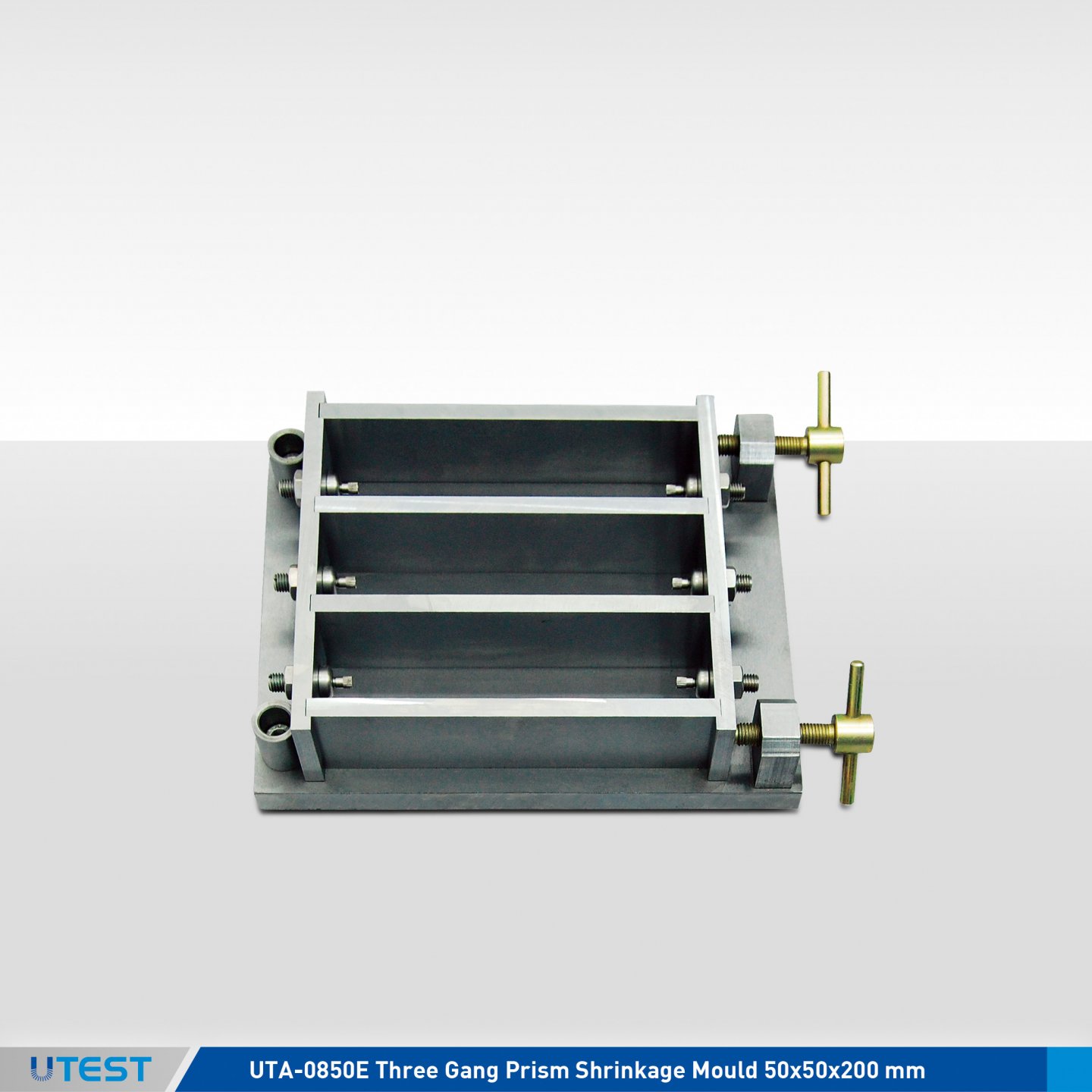
Product Code
|
UTA-0850E |
Three Gang Prism Shrinkage Mould 50x50x200 mm |
|
UTA-0851E |
Spare Steel Inserts for UTA-0850, 12 pcs. |
|
UTA-0856E |
Reference Rod, 205 mm Long with 6mm Tips |
|
UTA-0858 |
Reference Rod, 205 mm Long with 8mm Tips |
Standards
EN 1367-4; UNI 8520-22
The Three Gang Shrinkage Mould is used for the determination of the effect of aggregates on the drying, shrinkage and length change of hardened concrete when used together with the UTEST Length Comparators (UTCM-0200, UTCM-0210 or UTC-1170).
The mould is matchmarked and protected with anti-corrorion oil.
Reference rod and spare steel inserts should be ordered separately.
Shrinkage Mould is supplied complied with the steel inserts screwed on.

UTA-0856E
|
Dimensions |
220x330x70 mm |
|
Weight (approx.) |
15 kg |
32. Digital Length Comparator
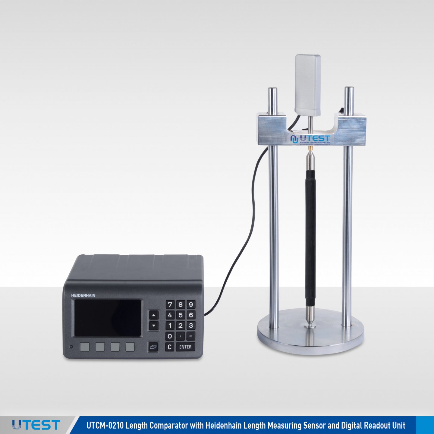
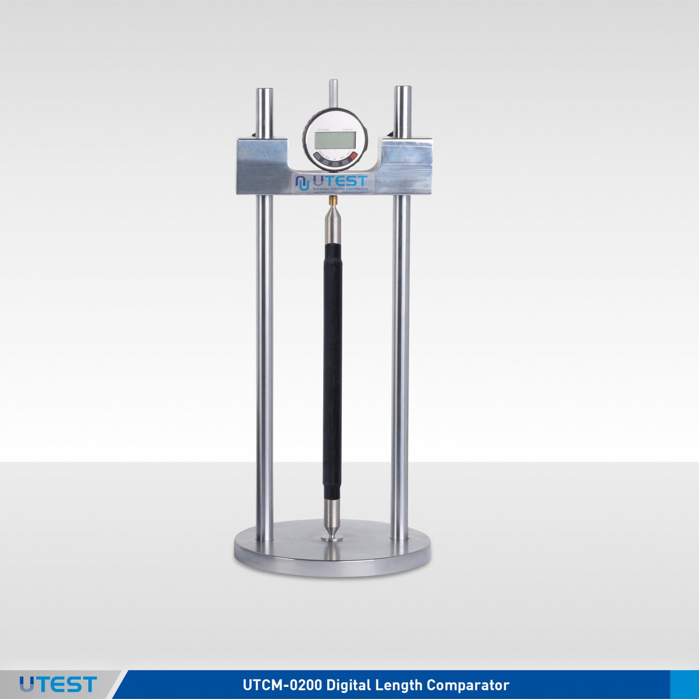

Product Code
|
UTCM-0200 |
Digital Length Comparator |
|
UTC-1170 |
Large Type Digital Length Comparator |
|
UTCM-0210 |
Length Comparator with Heidenhain Length Measuring Sensor and Digital Readout Unit |
Standards
EN 1367–4, 12617–4, 12808-4; ASTM C151, C157, C227, C311, C341,
C342, C441,C452, C490, C531, C596, C806, C878; BS 1881:5, 6073
Length Comparators are used to determine the length changes on different type of hardened mortar and concrete prisms with different sized.
The sets consist of a length measuring frame with measuring device attached to it. The comparators comes with 3 different models, UTCM-0200 and UTC-1170 are with 0.001 mm x 12,7 mm digital dial gauge and UTCM-0210 is with special 0.0001 mm x 30 mm transducer and readout unit. Horizontal clearance of UTCM-0200 is 150mm and UTC-1170 is 220mm.
All information about shrinkage moulds, steel inserts and reference rods can be seen on pages of UTCM-0029, UTCM-0033, UTA-0850, UTC-1153, UTC-1155 and UTC-1161.
Reference rods and moulds should be ordered separately according to test to be performed.
|
Product Code |
Dimensions |
Weight (approx.) |
|
UTCM-0200 |
180x180x420 mm |
4,75 kg |
|
UTC-1170 |
150x150x300 mm |
4 kg |
|
UTCM-0210 |
250x250x500 mm |
8 kg |
33. Alkali Aggregate Reaction Bath
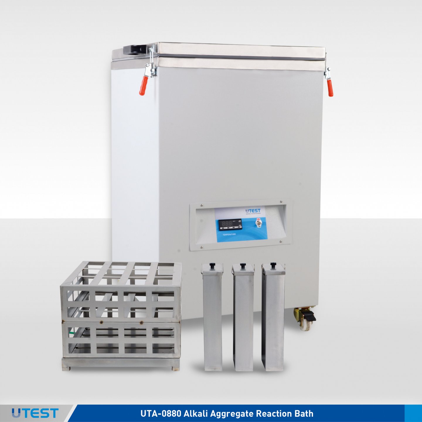
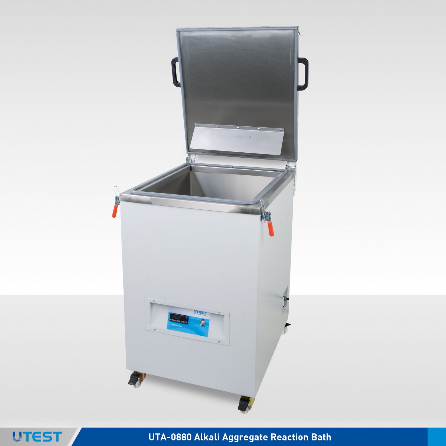
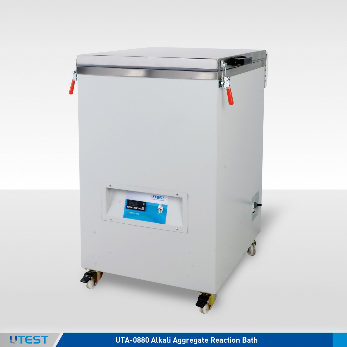
Product Code
|
UTA-0880 |
Alkali Aggregate Reaction Bath |
|
UTA-0882 |
Alkali Specimens Can, stainless steel, with an hanger which can hold 3 pcs. 25x25x285 mm specimens. |
|
UTCM-0033A |
Two Gang Prism Shrinkage Mould, 25x25x285 mm |
|
UTCM-0034 |
Steel Insert for ASTM C490, 12 pcs. |
|
UTCM-0035 |
Reference Rod 295 mm Long with Convex Hemispherical End |
|
UTCM-0200 |
Digital Length Comparator |
|
UTCM-0210 |
Length Comparator with Heidenhain Length Measuring Sensor and Digital Readout Unit |
|
UTC-1170 |
Large Type Digital Length Comparator |
|
Models for 220-240 V 50-60 Hz, 1ph. |
UTA-0880 |
|
Models for 110-120V 60 Hz, 1ph. |
UTA-0880-N |
Standards
CANADA CSA-A23.2-25A; For Moulds: ASTM C227, C490, C1260
The Alkali Aggregate Reaction Bath is used to keep 25x25x285 mm samples in NaOH (Sodium Hydroxide) or in any other solution at a specified temperature. The temperature can be adjusted between ambient to 80°C by using the digital controller.
The chamber of the bath is made of stainless steel and has a a capacity of 27 specimens (25x25x285 mm).
UTA-0880 is supplied complete with 3 pcs. stainless steel alkali specimens cans (UTA-0882). Each can has a stainless steel hanger which can hold 3 pcs. 25x25x285 mm specimens. Additional alkali specimens cans should be ordered separately.
UTCM-0033 is used to determine the potential alkali reactivity of cement-aggregate combinations (mortar-bar method). This mould is also used for determining the length change of hardened cement paste, mortar and concrete.
The test also requires UTCM-0200 or UTCM-0210 or UTC-1170 Length Comparators.
UTA-0880 Aggregate Reaction Bath can also be used as a general purpose water bath.
|
Dimensions |
560x700x950 mm |
|
Weight (approx.) |
63 kg |
|
Power |
2000 W |
34. Quantab Chloride Titrator Type
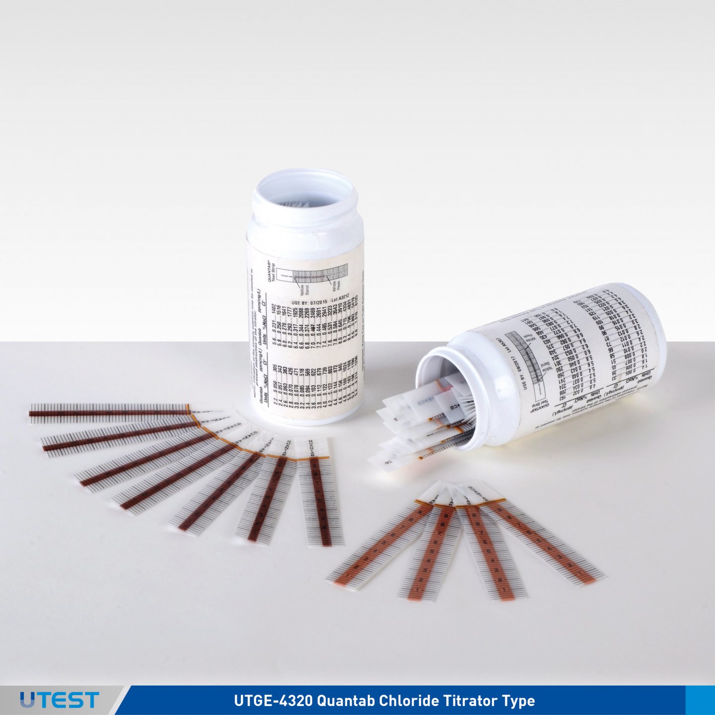
Product Code
|
UTGE-4320 |
Quantab Chloride Titrator Type 1175, 40 Strips |
|
UTGE-4322 |
Quantab Chloride Titrator Type 1176, 40 Strips |
Standards
BS 812:117 | BS 1377:3
The Quantab Chloride Titrators are used for quick determination of chloride content of fine aggregates. The determination is based on the reaction of the silver dichromate strip with the chloridein the sample solution, and the proportional content of chloride in the sample is indicated by the calibration chart which is supplied complete with the test kit.
Technical Specifications
|
|
Type 1175 |
Type 1176 |
|
Range |
0.005% to 0.1% NaCl |
0.05% to 1% NaCl |
|
Dimensions |
70x70x120 mm |
70x70x120 mm |
|
Weight (approx.) |
0,10 kg |
0,10 kg |
35. Reference Colours Glasses
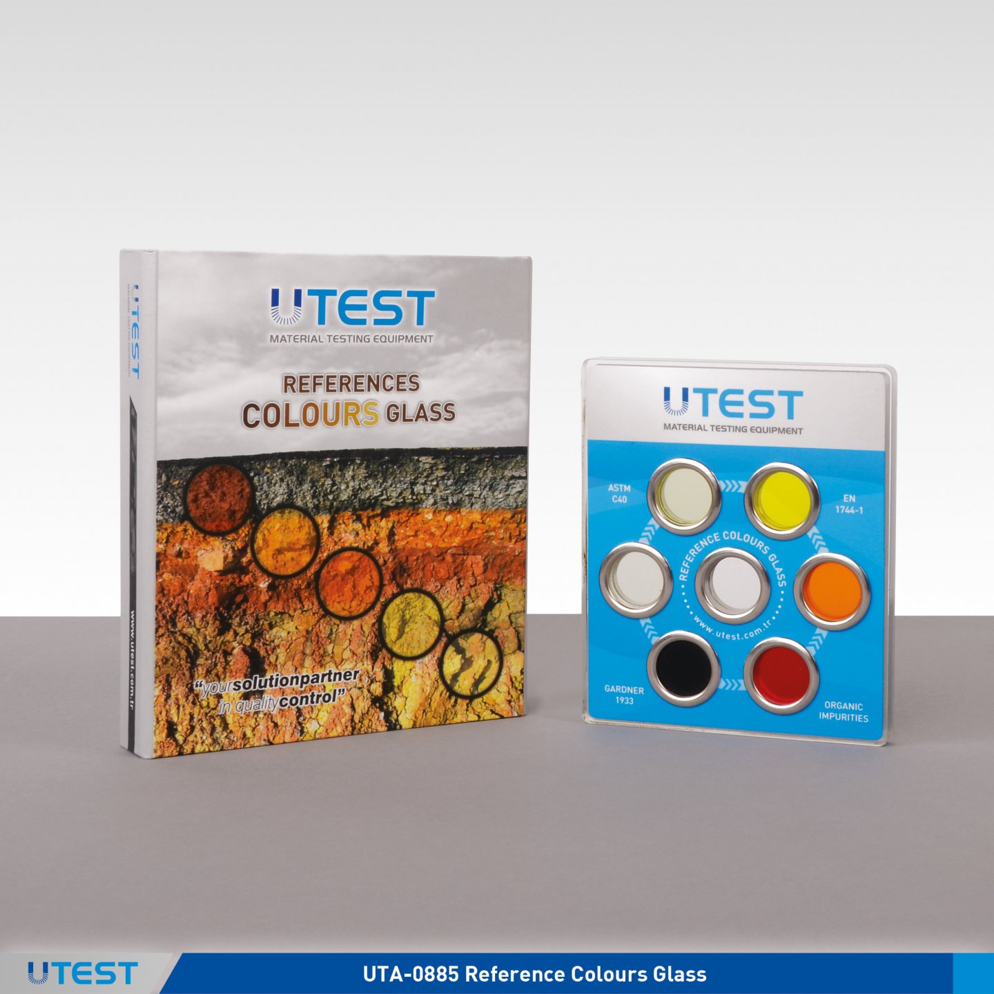
Product Code
|
UTA-0885 |
Reference Colours Glass |
|
UTGG-1705 |
Graduated Impurities Test, Glass Bottle 500 ml, ASTM |
|
UTGG-1710 |
Graduated Impurities Test, Glass Bottle 1000 ml, ASTM |
|
UTGG-1720 |
Cylindrical Glass Bottle with Cork Stopper, for Organic Impurities, 450 ml,EN |
|
UTGC-0840 |
Sodium Hydroxide 1 kg |
Standards
EN 1744-1; ASTM C40
The Reference Colour Glass consists of 5 organic glass scales mounted in a plastic holder, which is used for the comparison of the colour results from the relevant test.


UTGG-1720 450 ml Cylindrical Glass Bottle is used for determination of organic impurities as required in the EN standard.

UTGG-1705 and UTGG-1710 The 500 ml and 1000 ml capacity Graduated Glass Bottles are used for making reference standard colour and test solution according to the ASTM standard.
UTEST SOIL TESTING
-
Water Level Indicator
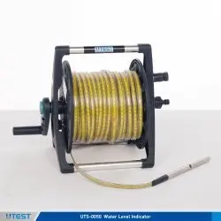
Product Code
|
UTS-0050 |
Water Level Indicator 50 m Cable Length |
|
UTS-0052 |
Water Level Indicator 100 m Cable Length |
|
UTS-0055 |
Water Level Indicator 150 m Cable Length |
|
UTS-0058 |
Water Level Indicator 200 m Cable Length |
The Water Level Indicators (Electric Contact Meters) are portable, easy-to-use and reliable instruments for measuring water level and total depth in bore holes, wells, observation pipes, reservoirs, as well as control of pumping tests.
As soon as the measuring probe electrode touches the water surface, the signal indicator on the instrument lights up with an audible alarm. The water level can be read on the measuring tape in meters (m) and centimeters (cm).
Technical Specifications
|
Measuring Range |
50 m, 100 m, 150 m, 200 m |
|
Sensitivity |
100 m cable length - smaller than 1 cm |
|
Probe |
Chromium-Nikel plated brass Standart Version: 14 mm dia. 140 mm long Special Version: 10 mm dia. 320 mm long |
|
Cable |
Polyamide coated steel tape with transparent polyethylene covering over 2 tinned copper conductors on both sides of the steel strip. |
|
Cable Metrics |
Dimensions in millimeters (mm), centimeters (cm) and decimeters (dm) on the yellow steel strip are colored in black and meters (m) in red. |
|
Cable Construction |
Transparent, hard plastic and heat resistant. |
|
Power Supply |
3V DC, 2piece AA size pen battery. Each one 1.5V |
|
Product Code |
Dimensions |
Weight (approx.) |
|
UTS-0050 |
350x350x350 mm |
7 kg (50 m) |
|
UTS-0052 |
350x350x350 mm |
10 kg (100 m) |
|
UTS-0055 |
350x350x400 mm |
12 kg (150 m) |
|
UTS-0058 |
350x350x400 mm |
15 kg (200 m) |
|
Product Code |
Dimensions |
Weight (approx.) |
|
UTS-0050 |
350x350x350 mm |
7 kg (50 m) |
|
UTS-0052 |
350x350x350 mm |
10 kg (100 m) |
|
UTS-0055 |
350x350x400 mm |
12 kg (150 m) |
|
UTS-0058 |
350x350x400 mm |
15 kg (200 m) |
2. Pocket Dial Penetrometer
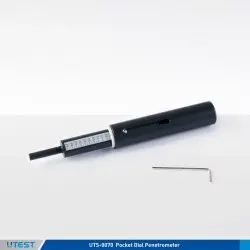
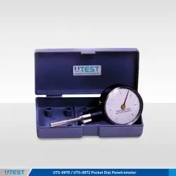
Product Code
|
UTS-0070 |
Pocket Dial Penetrometer, 0-6 kgf/cm2 |
|
UTS-0072 |
Pocket Dial Penetrometer, 0-14 kgf/cm2 |
|
UTS-0075 |
Pocket Dial Penetrometer, 0-6, 0-11 kgf/cm2 |
|
UTS-0078 |
Pocket Penetrometer, 0-5 kgf/cm2 |
The UTS Series of Pocket Dial Penetrometers are ideal instruments to determine the penetration resistance of cohesive soil, especially when various range measurements are required.
UTS-0075 Pocket Dial Penetrometer with respect to range and plunger diameters is avaliable for specific applications.
All Dial Penetrometer models have 60 mm. Dial Diameter and designed with Peak Hold Feature.
UTS-0075 Pocket Dial Penetrometer is used for evaluating the angle of internal friction “j” of sandy soils and the cohesion “c” 2 in clay soils. Dual scale: 0-6 kgf/cm for 6.35 mm diameter 2 plunger and 0-11 kgf/cm.
The UTS-0078 Pocket Penetrometer is a portable and easy-touse equipment to perform field classification of cohesive soils in terms of consistency, shear strength and approximate unconfined compressive strength.
|
Product Code |
Range (kg/cm') |
Plunger Dia. |
Dimensions |
Weigth (approx.) |
|
UTS-0070 |
0-6 |
6.35 |
80x150x40 mm |
0,20 kg |
|
UTS-0072 |
0-14 |
6.35 |
80x150x40 mm |
0,20 kg |
|
UTS-0075 |
0-6, 0-11 |
6.35-10-15-20-25 |
80x150x40 mm |
0,20 kg |
|
UTS-0078 |
0-5 |
6.35 |
30x180x30 mm |
0,10 kg |
3. Augers Power Head
Product Code
|
UTS-0005 |
Augers Power Head |
|
UTS-0008 |
Single Flute Bit Ø:80x1000 mm |
|
UTS-0010 |
Single Flute Bit Ø:100x1000 mm |
|
UTS-0015 |
Single Flute Bit Ø:150x1000 mm |
|
UTS-0020 |
Single Flute Bit Ø:200x1000 mm |
Standards
ASTM D420, D1452; AASHTO T86, T202; CNR a. VI n.25
Used in conjunction with sampling tubes to obtain disturbed or undisturbed soil samples. The flute bits with 80-100-150-200 mm diameters should be ordered separately.
|
UTS-0005 Properties |
|
|
Motor Power |
1,6 kW |
|
Cylinder Volume |
50,2 cc |
|
Reduction Ratio |
40:1 |
|
Product Code |
Dimensions |
Weigth |
|
UTS-0005 |
580x1300x580 mm |
10 kg |
|
UTS-0008 |
70x80x290 mm |
1 kg |
|
UTS-0010 |
90x100x300 mm |
1,50 kg |
|
UTS-0015 |
120x150x320 mm |
2 kg |
|
UTS-0020 |
150x200x350 mm |
4 kg |
4. Hand Operated Auger Boring Set
Product Code
|
UTS-0024 |
Hand Operated Auger Boring Set |
|
UTS-0026 |
Extension Rod for UTS-0024, 1 meter |
|
UTS-0027 |
T-Handle with 1 m Rod |
|
UTS-0028 |
Auger Head Set, Ø:80 mm Ø:100 mm and Ø:150 mm |
UTS-0024 Hand Boring and Sampling Set for augering down to a depth of 5 meters.
The UTS-0024 Hand Operated Auger Boring Set consists of a T-Handle with 1 m Rod, 1 m Extension Rod, 80 mm, 100 mm and 150 mm diameter Auger Heads.
|
Dimensions |
400x1200x250 mm |
|
Weigth (approx.) |
12 kg |
5. Field Inspection Testing Kit
Product Code
|
UTS-0080 |
Field Inspection Testing Kit |
|
UTS-0082 |
Field Inspection Pocket Vane Tester |
|
UTS-0083 |
Extension Rod for UTS-0082 |
|
UTS-0084 |
Heavy Duty Pocket Penetrometer, 0-10 kgf/cm² |
Standards
ASTM D2573
The UTS-0080 Field Inspection Testing Kit is ideal for geotechnicians, geologists and agronomists. It consists of the UTS-0084 Pocket Penetrometer and of the UTS-0082 Field Inspection Pocket Vane Tester. The instrument is contained in a practical carrying case.
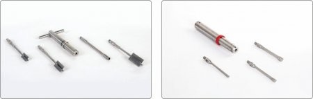
UTS-0082 UTS-0084
|
UTS-0080 Field Inspection Testing Kit |
|
|
Dimensions (packed) |
300x390x100 mm |
|
Weigth (approx.) |
1,50 kg |
The UTS-0082 Field Inspection Pocket Vane Tester is especially designed to measure the undrained shear strength (CU) of cohesive soils, consists of a cylindrical body with a torsional spring and three interchangeable vanes of different sizes used depending upon the expected strength of the soil. The height/diameter ratio of all vanes is 2. During operation the vane is driven for 5-6 cm into the soil and then turned with the handle. Deep measures (i.e. on the top of undisturbed samples) can be obtained using the extension rod. All stainless steel construction. Supplied in a plastic case. Extension rod should be ordered separately.
|
UTS-0082 Field Inspections Pocket Vane Tester |
|
|
Vane Dimensions (height x dia.) |
32x16 mm, 40x20 mm, 50.8x25.4 mm |
|
Measuring Range |
0 to 240 kPa (0-24 N/cm') |
|
Torque Value |
5 N - m |
|
Extension Rod |
500 mm depth |
|
Overall Dimensions (assembled) |
100x300x50 mm |
|
Weight |
1,20 kg |
The UTS-0084 Heavy Duty Pocket Penetrometer is designed for making field classification of cohesive soils in terms of consistency, shear strength and approximate unconfined compressive strength. Heavy duty model is all stainless steel construction, three interchangeable tips: 4.5 mm dia. for very hard soil, 6.35 mm for medium and soft soil, 8.98 mm for soft soil. Supplied complete with plastic case.
|
UTS-0084 Heavy Duty Pocket Penetrometer |
|
|
Measuring Range |
0 to 10 kgf/cm' |
|
Dimensions (assembled) |
210 mm length x 20 mm dia. |
|
Weight (approx.) |
1 kg |
6. Pocket Shear Vane Device
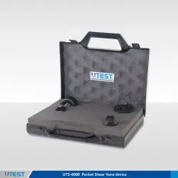
Product Code
|
UTS-0088 |
Pocket Shear Vane Device |
The UTS-0088 Pocket Shear Vane Device is a practical equipment for determining the shear strength of cohesive soils. It is widely used to perform onsite measurements of excavations covering trenches and test pits, thin-wall or split core samples, by providing a quick and efficient method for shear strength measurements and it is also suitable for laboratory usage. Pocket Shear Vane Device is supplied in a plastic carrying case.
|
Vane Type |
Range |
|
Standard 25 mm Diameter Vane |
0-10 N/cm² |
|
Sensitive Vane Adaptor |
0-2 N/cm² |
|
High Capacity Vane Adaptor |
0-25 N/cm² |
|
Dimensions |
220x230x50 mm |
|
Weight (approx.) |
0,30 kg |
7. TRL Dynamic Cone Penetrometer

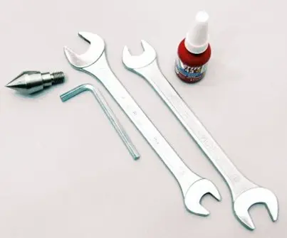
Product Code
|
UTS-0095 |
TRL Dynamic Cone Penetrometer (DCP) |
Standards
ASTM D 6951
The UTS-0095 TRL Dynamic Cone Penetrometer is used for the rapid, in situ measurement of structural properties of existing road pavement constructed with unbound materials.
The design of the DCP is similar to that described by Kleyn, Maree and Savage (1982); it incorporates an 8 kg weight dropping through a height of 575 mm and 60° cone having a diameter of 20 mm. with the standard DCP measurements can be made down to a depth of approximately 850 mm or when extension shafts are used to a recommended maximum depth of 2 m.
Readings are usually taken after a set number of blows, changing the number according to the strength of the layer being penetrated. A typical test takes only a few minutes, therefore the instrument provides a very efficient method of obtaining information that would normally require the digging of test pits.
The penetration hammer assembly consists of 8 kg hammer, hammer shaft, anvil with plastic plate coupling for ruler and handle.
The TRL Dynamic Cone Penetrometer is supplied complete with;
- A hammer assembly,
- Penetration rod,
- 2 piece 60° cone,
- Metal plate coupling for ruler,
- Segmented adaptor for extension rods,
- Segmented upper extension rod,
- Segmented lower extension rod,
- 2 piece 13-17mm AF spanners,
- 3mm AF hex wrench,
- Tommy bar,
- A bottle of adhesive,10cc,
- Users Manual
- Steel ruler,
- Carrying Case, heavy-duty wooden
|
Dimensions |
220x1200x170 mm |
|
Weight (approx.) |
24 kg |
8. Universal Speedy Moisture Tester
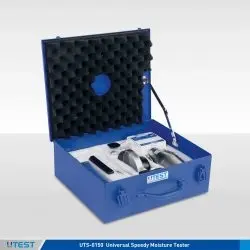
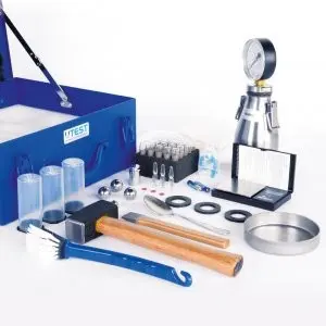
Product Code
|
UTS-0150 |
Universal Speedy Moisture Tester |
UTS-0150 Universal Speedy Moisture Tester is used to determine the moisture content of soils, sand and fine aggregates in the field. It is an easy and portable method. The amount of gas, which is given off when water and calcium carbide are mixed and react, is directly proportional to the amount of water present in the sample and results in percentage moisture are taken from a pressure gauge.
The Universal Speedy Moisture Tester is supplied complete with;
- Calibrated pressure bottle with surface thermometer
- Mechanical manometer up to 1,6 bar direct reading of humidity for the weights 20g, 50g and 100g
- Steel ball set (Ø10 mm/3 pcs. and Ø5,5 mm/1 pcs.)
- Digital sample scale up to 200g
- 25 normed carbide ampoules with 7g calcium carbide according to DIN 18560-4
- Other measurement accessories
- Double-walled plastic case
|
Dimensions |
380x400x150 mm (case) |
|
Weight (approx.) |
9,50 kg |
9. Speedy Moisture Tester
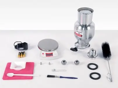
Product Code
|
UTS-0155 |
Speedy Moisture Tester |
Standards
ASTM D4944; AASHTO T217
The UTS-0155 Speedy Moisture Tester is used to determine the moisture content of soils, sand and fine aggregates in the field. It is an easy and portable method. The amount of gas, which is given off when water and calcium carbide are mixed and react, is directly proportional to the amount of water present in the sample and results in percentage moisture are taken from a pressure gauge.
These model is used for moisture determination of a 20 g specimen with 20% maximum moisture content. UTS-0155 Speedy Moisture Tester does not include Calcium Carbide Powder.
The Speedy Moisture Tester is supplied complete with;
- Vessel with Gauge
- Digital Scale
- Scoop
- Cleaning Brush
- Cleaning Cloth
- Two Steel Pulverizing Balls
- Plastic Case
|
Dimensions |
210x370x530 mm (case) |
|
Weight (approx.) |
7 kg |
10. Hand Operated Hydraulic Specimen Extruder
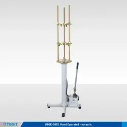
Product Code
|
UTGE-0082 |
Hand Operated Hydraulic Specimen Extruder, Vertical Type, 60 kN Capacity |
Standards
EN 13286-2, 13286-47, 12697-30; AASHTO T134, T180, T193,
T245; ASTM D698, D1557, D1883, D1559; BS 1377-4, 1924-2,
598-107
The UTGE-0082 Hand Operated Hydraulic Extruder is designed for extruding specimens from 50 mm (2”) to 125 mm (5”) (outer dia.) shelby sample tubes and moulds such as proctor, CBR and marshall moulds.
Also useful for sampling and removing uniaxial and triaxial test specimens to/from the cutters inner dia. from 38 mm to 100 mm. The extruder has 60 kN extrusion force and 650 mm ram travel.
To remove the sample from the shelby tubes, adapter sets of different sizes in the table below should be ordered separately.
Supplied complete with;
- Adapter sets for Ø150 mm (6”) and Ø100 mm (4”) inner dia. moulds
- Flanges and head sets for Ø38 mm, Ø50 mm, Ø70 mm and 100 mm (only flange) inner dia. cutters.
|
For UTS-0082 |
||
|
UTGE-0110 |
Adaptor Set for 2" (50,8mm) Outer Dia Shelby Tubes. |
Includes a ring with 48,5mm ID. and an extruder head with Ø43,5mm. |
|
UTGE-0112 |
Adaptor Set for 2 ½” (63,5 mm) Outer Dia Shelby Tubes. |
Includes a ring with 61mm ID. and an extruder head with Ø56mm. |
|
UTGE-0114 |
Adaptor Set for 3" (75 mm) Outer Dia Shelby Tubes. |
Includes a ring with 72mm ID. and an extruder head with Ø67mm. |
|
UTGE-0116 |
Adaptor Set for 3 1/4" (83 mm) Outer Dia Shelby Tubes. |
Includes a ring with 79,5mm ID. and an extruder head with Ø74,5mm. |
|
UTGE-0118 |
Adaptor Set for 3 1/2" (88,9 mm) Outer Dia Shelby Tubes. |
Includes a ring with 85mm ID. and an extruder head with Ø80mm. |
|
UTGE-0120 |
Adaptor Set for 100 mm Outer Dia Shelby Tubes. |
Includes a ring with 96mm ID. and an extruder head with Ø91mm. |
|
UTGE-0122 |
Adaptor Set for Ø4" (101,6 mm) Outer Dia Shelby Tubes. |
Includes a ring with 97,5mm ID. and an extruder head with Ø92,5mm. |
|
UTGE-0124 |
Adaptor Set for 4 1/2" (114,3 mm) Outer Dia Shelby Tubes. |
Includes a ring with 109mm ID. and an extruder head with Ø104mm. |
|
UTGE-0125 |
Adaptor Set for 5" (125 mm) Outer Dia Shelby Tubes. |
Includes a ring with 119mm ID. and an extruder head with Ø114mm. |
|
Dimensions |
470x650x1900 mm (case) |
|
Weight (approx.) |
82 kg |
11. Motorized Hydraulic Specimen Extruder, Horizontal Type, 60 kN Capacity
Product Code
|
UTGE-0084 |
Motorized Hydraulic Specimen Extruder, Horizontal Type, 60 kN Capacity |
|
Models for 220-240V 50-60 Hz, 1ph |
UTGE-0084 |
|
Models for 110-120V 60 Hz, 1ph |
UTGE-0084-N |
Standards
EN 13286-2, 13286-47, 12697-30; AASHTO T134, T180, T193, T245;
ASTM D698, D1557, D1883, D1559; BS 1377-4, 1924-2, 598-107
The UTGE-0084 Motorized Hydraulic Extruder, Horizontal Type is designed for extruding specimens from 50 mm (2”) to 125 mm(5”) (outer dia.) shelby sample tubes and moulds such as proctor, CBR and marshall moulds. Also useful for sampling and removing uniaxial and triaxial test specimens to/from the cutters inner dia. from 38mm to 100mm.
The Extruder has 60 kN capacity and 900 mm ram travel. The hydraulic piston can be stopped at any position during the extraction.
To remove the sample from the shelby tubes, adapter sets of different sizes in the table below should be ordered separately.
The Motorized Hydraulic Extruder is supplied complete with ;
- Adapter sets for Ø100 mm (4”) and Ø150 mm (6”) inner dia. moulds
- Flanges and head sets for Ø38mm, Ø50mm, Ø70 mm and 100mm (only flange) inner dia. cutters.
|
For UTS-0084 |
||
|
UTGE-0110 |
Adaptor Set for 2" (50,8mm) Outer Dia Shelby Tubes. |
Includes a ring with 48,5mm ID. and an extruder head with Ø43,5mm. |
|
UTGE-0112 |
Adaptor Set for 2 ½” (63,5 mm) Outer Dia Shelby Tubes. |
Includes a ring with 61mm ID. and an extruder head with Ø56mm. |
|
UTGE-0114 |
Adaptor Set for 3" (75 mm) Outer Dia Shelby Tubes. |
Includes a ring with 72mm ID. and an extruder head with Ø67mm. |
|
UTGE-0116 |
Adaptor Set for 3 1/4" (83 mm) Outer Dia Shelby Tubes. |
Includes a ring with 79,5mm ID. and an extruder head with Ø74,5mm. |
|
UTGE-0118 |
Adaptor Set for 3 1/2" (88,9 mm) Outer Dia Shelby Tubes. |
Includes a ring with 85mm ID. and an extruder head with Ø80mm. |
|
UTGE-0120 |
Adaptor Set for 100 mm Outer Dia Shelby Tubes. |
Includes a ring with 96mm ID. and an extruder head with Ø91mm. |
|
UTGE-0122 |
Adaptor Set for Ø4" (101,6 mm) Outer Dia Shelby Tubes. |
Includes a ring with 97,5mm ID. and an extruder head with Ø92,5mm. |
|
UTGE-0124 |
Adaptor Set for 4 1/2" (114,3 mm) Outer Dia Shelby Tubes. |
Includes a ring with 109mm ID. and an extruder head with Ø104mm. |
|
UTGE-0125 |
Adaptor Set for 5" (125 mm) Outer Dia Shelby Tubes. |
Includes a ring with 119mm ID. and an extruder head with Ø114mm. |
|
Capacity |
60 kN |
|
Ram Travel |
900 mm |
|
Dimensions |
420x2000x1200 mm |
|
Weigth (approx.) |
195 kg |
|
Power |
750 W |
12. Motorized Hydraulic Specimen Extruder Vertical Type
Product Code
|
UTGE-0086 |
Motorized Hydraulic Specimen Extruder Vertical Type, 60 kN Capacity |
|
Models for 220-240V 50-60 Hz, 1ph |
UTGE-0086 |
|
Models for 110-120V 60 Hz, 1ph |
UTGE-0086-N |
Standards
EN 13286-2, 13286-47, 12697-30; AASHTO T134, T180, T193, T245;
ASTM D698, D1557, D1883, D1559; BS 1377-4, 1924-2, 598-107
The UTGE-0086 Motorised Hydraulic Extruder, Vertical Type is designed for extruding specimens from 50 mm (2”) to 125 mm (5”) (outer dia.) shelby sample tubes and moulds such as proctor, CBR and marshall moulds. Also useful for sampling and removing uniaxial and triaxial test specimens to/from the cutters inner dia. from 38 mm to 100 mm.
The Extruder has 60 kN capacity and 650 mm ram travel. The hydraulic piston can be stopped at any position during the extraction.
To remove the sample from the shelby tubes, the adapter sets of different sizes on the table in next page of UTGE-0082 should be ordered separately.
The Motorised Hydraulic Extruder is supplied complete with;
- Adapter sets for Ø100 mm (4”) and Ø150 mm (6”) inner dia. moulds
- Flanges and head sets for Ø38 mm, Ø50 mm, Ø70 mm and 100 mm (only flange) inner dia. cutters.
|
For UTS-0086 |
||
|
UTGE-0110 |
Adaptor Set for 2" (50,8mm) Outer Dia Shelby Tubes. |
Includes a ring with 48,5mm ID. and an extruder head with Ø43,5mm. |
|
UTGE-0112 |
Adaptor Set for 2 ½” (63,5 mm) Outer Dia Shelby Tubes. |
Includes a ring with 61mm ID. and an extruder head with Ø56mm. |
|
UTGE-0114 |
Adaptor Set for 3" (75 mm) Outer Dia Shelby Tubes. |
Includes a ring with 72mm ID. and an extruder head with Ø67mm. |
|
UTGE-0116 |
Adaptor Set for 3 1/4" (83 mm) Outer Dia Shelby Tubes. |
Includes a ring with 79,5mm ID. and an extruder head with Ø74,5mm. |
|
UTGE-0118 |
Adaptor Set for 3 1/2" (88,9 mm) Outer Dia Shelby Tubes. |
Includes a ring with 85mm ID. and an extruder head with Ø80mm. |
|
UTGE-0120 |
Adaptor Set for 100 mm Outer Dia Shelby Tubes. |
Includes a ring with 96mm ID. and an extruder head with Ø91mm. |
|
UTGE-0122 |
Adaptor Set for Ø4" (101,6 mm) Outer Dia Shelby Tubes. |
Includes a ring with 97,5mm ID. and an extruder head with Ø92,5mm. |
|
UTGE-0124 |
Adaptor Set for 4 1/2" (114,3 mm) Outer Dia Shelby Tubes. |
Includes a ring with 109mm ID. and an extruder head with Ø104mm. |
|
UTGE-0125 |
Adaptor Set for 5" (125 mm) Outer Dia Shelby Tubes. |
Includes a ring with 119mm ID. and an extruder head with Ø114mm. |
|
Capacity |
60 kN |
|
Ram Travel |
650 mm |
|
Dimensions |
550x730x2010 mm |
|
Weigth (approx.) |
190 kg |
|
Power |
750 W |
12. MARSHALL / CBR / PROCTOR SPECIMEN EXTRUDER
Product Code
|
UTGE-0080 |
Marshall / CBR / Proctor Specimen Extruder, 30 kN Capacity |
Standards
EN 13286-2, 13286-47, 12697-30; AASHTO T134, T180, T193,
T245; ASTM D698, D1557, D1883, D1559; BS 1377-4, 1924-2,
598-107
The UTGE-0080 Extruder is designed to easily extrude specimens from marshall and CBR, standard and modified proctor moulds. The capacity of the extruder is 30 kN and is supplied complete with a manual hydraulic jack and 2 pcs. adaptor to extrude specimens from Ø100 mm (4”) and Ø150 mm (6”) dia. proctor, CBR and marshall molds.
Adaptors with different sizes should be ordered separately if required.
|
Ram Travel |
130 mm |
|
Screw Travel |
90 mm |
|
Dimensions |
280x280x510 mm |
|
Weight (approx.) |
28 kg |
13. Melting Pot
Product Code
|
UTC-1070 |
Melting Pot, 3 L Capacity |
Standards
CEN ISO/TS 17892-2; EN 12390–3, 12390-1, 12504-1; ASTM C31, C192, C617; AASTHO R100, R39
|
Models for 220-240V 50-60 Hz, 1ph. |
UTC-1070 |
|
Models for 110-120V 60 Hz, 1ph. |
UTC-1070-N |
The Melting Pot is designed for melting capping compound, sulphur, wax and similar materials. The melted paraffin wax is used to seal soil samples and other materials.
The apparatus consists of a 3 liter capacity aluminum container in a well-lagged steel jacket, cover and a thermostatic control heating system to keep the temperature constant in the range of ambient to 200°C.
|
Dimensions |
300x340x240 mm |
|
Weigth (approx.) |
10 kg |
|
Power |
600 W |
14. Soil Lathe / Trimmer and Extruder
Product Code
|
UTS-0160 |
Soil Lathe / Trimmer and Extruder |
|
UTS-0164 |
Wire Saw with one Blade |
|
UTS-0165 |
Wire Saw Blade for UTS-0164 (pack of 10) |
|
UTS-0166 |
Trimming Knife |
|
UTGG-2205 |
Porcelain Mortar with Pestle 130 mm dia |
|
UTGG-2215 |
Rubber Headed Pestle |
The UTS-0160 Soil Lathe, Trimmer and Extruder is used to extrude and trim soil samples from 35 mm to 100 mm diameter to reduce samples.
Wire Saw, Trimming Knife, Porcelain Mortar with Pestle, the Rubber Headed Pestle can be ordered separately.
Technical Specifications
|
Specimen Lathe |
35x70 mm to 100x200 mm |
|
Specimen Trimming and Extrusion |
35x70 mm to 50x100 mm |
|
Vertical Daylight |
260 mm |
|
Dimensions |
230x300x430 mm |
|
Weight (approx.) |
14 kg |
15. Laboratory Mixer
Product Code
|
UTG-0130 |
Laboratory Mixer 10 L, 220-240 V 50-60 Hz |
|
UTAS-0187 |
Heating Mantle for UTG-0130 |
|
UTG-0131 |
Spare Bowl for UTG-0130 |
|
UTG-0132 |
Spare Whisk for UTG-0130 |
|
Models for 220-240V 50-60 Hz, 1 ph. |
UTG-0130 |
UTAS-0187 |
|
Models for 110-120V 60 Hz, 1 ph. |
UTG-0130-N |
UTAS-0187-N |
The UTG-0130 10 litre capacity Laboratory Mixer is designed for mixing of soil and asphalt samples to be used for mechanical tests such as compaction, indirect tensile, Marshall etc. The mixing head rotates at speeds of 10 to 240 r.p.m. and the whisk from 20 to 480 r.p.m. The user can adjust rotation speed between given values easily by using a control knob fitted to the front panel.
The bituminous mixture must be prepared at the prescribed temperature according to the EN standard. For this reason the mixer can be equipped with thermostatically controlled heater.
The Heating Mantle (Isomantle heater) has a digital thermostatic controller and used for heating the bituminous mixtures in the UTG-0130 up to 150°C. The Isomantle heater is supplied complete with PT100 temperature sensor.
Heating Mantle should be ordered separately.
The Laboratory Mixer is supplied complete with;
- Bowl, 10 lt Capacity Stainless Steel
- Mixing Whisk
UTG-0131 UTG-0132
|
Product Code |
UTG-0130 |
UTAS-0187 |
|
Dimensions |
600x620x700 mm |
310x380x200 mm |
|
Weight (approx.) |
65 kg |
6 kg |
|
Power |
550 W |
600 W |
16. Liquid Limit / Semi-Automatic Cone Penetrometer
Product Code
|
UTS-0180 |
Semi-Automatic Cone Penetrometer for Liquid Limit |
|
UTS-0182 |
Liquid Limit Penetration Test Cone, Stainless Steel, 30° and 80 g |
|
UTS-0183B |
Cone Test Gauge for 30° Angle Cone, BS |
|
UTS-0183E |
Cone Test Gauge for 30° Angle Cone, EN ISO |
|
UTS-0184 |
Liquid Limit Penetration Test Cone, Stainless Steel, 60° and 60 g |
|
UTS-0185E |
Cone Test Gauge for 60° Angle Cone, EN ISO |
|
UTS-0187E |
Liquid Limit Penetration Test Cone, Stainless Steel, 30° and 100g, EN ISO |
|
UTGH-1435 |
Penetration Sample Cup / Moisture Content Tin with Lid, 75x50mm, Aluminum |
|
UTGH-1440 |
Penetration Sample Cup / Moisture Content Tin with Lid. Ø55x30 mm, Aluminium |
|
UTGH-1442 |
Penetration Sample Cup / Moisture Content Tin with Lid. Ø55x40mm, Aluminium |
|
UTGH-1444 |
Penetration Sample Cup / Moisture Content Tin with Lid. Ø55x40mm, Stainless Steel |
|
Models for 220-240V 50-60 Hz, 1ph |
UTS-0180 |
|
Models for 110-120V 60 Hz, 1ph |
UTS-0180-N |
Standards
BS 1377:2; NF P94-052-1; EN ISO 17892-6, 17892-12
The Cone Penetrometer is used to determine the moisture content at which clay soils pass from a plastic to a liquid state and used also for the determination of undrained shear strength.
UTS-0180 Semi-Automatic Cone Penetrometer for liquid limit consists of a frame with a levelling screws and screw gear assembly with handwheel for vertical adjustment, a digital penetration measurement gauge with 0.01 mm resolution /readibility, a digital timer, a magnifying lens and a low voltage illuminator mounted on flexible arms.
Penetration time 0-99 sec. can be set up by user with the digital timer. The timer will allow the cone to free fall into the sample for the engaged time interval and then lock the cone from advancing while providing a direct reading of the test results.
Each cone supplied complete with its shaft. Penetration cone/s, cone test gauges and sample cups should be ordered seperately.
|
UTGH-1435 |
UTGH-1440 |
UTGH-1442 |
UTGH-1444 |
|
Ø (75±2) mm x h (50±2) mm |
Ø (55+2) mm x h (30±2) mm |
Ø (55+2) mm x h (40±2) mm |
Ø (55+2) mm x h (40±2) mm |
|
Dimensions |
210x220x500 mm |
|
Weight (approx.) |
14 kg |
17. Liquid Limit Casagrande Device
Product Code
|
UTS-0200B |
Manual Liquid Limit Device (Casagrande), BS |
|
UTS-0202A |
Manual Liquid Limit Device (Casagrande), ASTM-AASHTO |
|
UTS-0202E |
Manual Liquid Limit Device (Casagrande), EN, ISO |
|
UTS-0210B-T |
Motorized Liquid Limit Device (Casagrande), BS, 220-240V 50 Hz, 1 ph. |
|
UTS-0212A |
Motorized Liquid Limit Device (Casagrande), ASTM-AASHTO |
|
UTS-0212E-T |
Motorized Liquid Limit Device (Casagrande), EN, ISO |
|
UTS-0215A |
Metal Grooving Tool and Gauge Block, ASTM |
|
UTS-0215E |
Metal Grooving Tool and Gauge Block, EN, ISO |
|
UTS-0216A |
Plastic Grooving Tool, ASTM |
|
UTS-0217B |
Plastic Grooving Tool, BS |
|
UTS-0218E |
Brass Grooving Tool, EN ISO |
|
UTS-0218EH |
Brass Grooving Tool, AASHTO, EN ISO |
|
UTS-0220A |
Resilience (Rebound) Tester, ASTM |
|
UTS-0221EH |
Resilience (Rebound) Tester, AASHTO, EN ISO, TS 1900-1 |
|
UTS-0225A |
Spare Brass Cup, for ASTM, AASHTO, TS 1900-1 Models |
|
UTS-0225E |
Spare Brass Cup, for EN, ISO Model |
|
Models for 220-240V 50 Hz, 1 ph. |
UTS-0212A-T |
|
Models for 110-120V 60 Hz, 1 ph. |
UTS-0212A-N |
|
Models for 220-240V 60 Hz, 1 ph. |
UTS-0212A-K |
Standards
ASTM D4318; BS 1377:2; AASHTO T89; EN ISO 17892-12
The UTEST Manual and Motorized Liquid Limit Apparatus (Casagrande) are used to determine the moisture content at which clay soils pass from plastic to liquid state.
The devices consist of an adjustable crank and cam mechanism, a blow counter and a removable brass cup fitted on the base. Different models with the same shape but with different base and cup weights are available according to the required specifications. Manual and Motorized versions are available.
The grooving tools which differ according to the preferred test standard should be ordered separately.
|
|
Manual |
Motorized |
|
Dimesions |
150x200x130 mm |
200x280x160 mm |
|
Weight (approx.) |
2 kg |
4 kg |
18. Plastic Limit Test Set
Product Code
|
UTS-0250 |
Plastic Limit Test Set |
|
UTS-0252 |
Plastic Limit Reference Rod Ø 3x100 mm |
|
UTS-0254 |
Plastic Limit Plate 300x300x10 mm, Glass |
|
UTGG-2170 |
Porcelain dish, 120 mm dia. |
|
UTGH-1433 |
Moisture content tin with lid, Aluminum, Ø:75 mm, h:30 |
|
UTGH-1495 |
Spatula, small, length:100 mm |
|
UTGP-1000 |
Piset, 250 ml |
Standards
ASTM D4318; AASHTO T90; BS 1377:2; EN, ISO 17892-12; UNE 103-104; UNI 10014
The plastic limit (PL) is defined as the lowest moisture content of a soil that will permit a sample to be rolled into threads of 3 mm diameter without the threads breaking.
The Plastic Limit Test Sets are is supplied complete with;
- A Glass Plate, 300x300x10 mm (one face ground)
- Steel Reference Rod, Ø3 mm
- Moisture Content Tins, Ø:75 mm, h:30, 6 pcs.
- Porcelain Mixing Dish, 120 mm dia.
- Spatula, 100 mm
- Carrying Case
- Piset 250 ml
|
Dimensions |
380x500x120 mm |
|
Weight (approx.) |
3,50 kg |
19. Shrinkage Limit Test Set
Product Code
|
UTS-0230 |
Shrinkage Limit Test Set |
|
UTS-0234 |
Shrinkage Prong Plate |
|
UTGH-1425 |
Moisture Content Tin with Lid, Aluminium, Ø:55 mm h:35 mm |
|
UTGH-1430 |
Moisture Content Tin with Lid, Aluminium, Ø:45 mm h:10 mm |
|
UTGG-2170 |
Porcelain dish, 120 mm dia. |
|
UTGH-1495 |
Spatula, small, length:100 mm |
|
UTGG-1005 |
Graduated glass cylinder 25 ml |
Standards
ASTM D427; AASHTO T92; UNE 103-108; UNI 10014
When the water content of a fine-grained cohesive soil is reduced below the plastic limit, shrinkage of the soil mass continues until the shrinkage limit is reached.
This method of test covers the determination of the shrinkage limit, shrinkage ratio, volumetric shrinkage and linear shrinkage.
The Shrinkage Limit Test Set is supplied complete with;
- Prong Plate
- Moisture Content Tin with Lid, aluminum, Ø:45 mm h:10 mm, 2 pcs.
- Moisture Content Tin with Lid, aluminum, Ø:55 mm h:35 mm
- Porcelain Dish, 120 mm dia.
- Spatula, 100 mm
- Graduated Glass Cylinder, 25 ml,
- Carrying Case
|
Dimensions |
280x330x80 mm |
|
Weight (approx.) |
1 kg |
20. Linear Shrinkage Mould
Product Code
|
UTS-0235 |
Linear Shrinkage Mould |
Standards
BS 1377:2
The UTS-0235 Linear Shrinkage Mould is 140 mm long and 12.5 mm radius and is used for the determination of the total linear shrinkage of soils, and indicates the plastic properties of soils with low clay content.
|
Dimesions |
40x150x20 mm |
|
Weight (approx.) |
0,3 kg |
21. Sedimentation (Hydrometer) Test Set
Product Code
|
UTS-0270 |
Hydrometer Test Set |
|
UTS-0272E |
Soil Dispersion Mixer, 220-240 V 50-60 Hz, 1 ph |
|
UTS-0272 |
Soil Dispersion Mixer, ASTM, AASHTO, EN 220-240 V 50-60 Hz, 1 ph |
|
UTS-0273 |
Hydrometer Bath, 220-240 V 50-60 Hz |
|
UTS-0274 |
Hydrometer 151H |
|
UTS-0275 |
Hydrometer 152H |
|
UTS-0276 |
Hydrometer Jar (Sedimentation Cylinder), 1000 ml |
|
UTGC-0900 |
Sodium Hexametaphosphate, 1 kg |
Standards
ASTM D7928; AASHTO T88; EN ISO 17892-4
Hydrometer Test Set is used to determine the particle size distribution of very fine materials such as silt and clay.
Soil dispersion mixer which are necessary for the test should be ordered separately.
50 L (8 cylinders) capacity hydrometer bath complete with a circulating unit, a heater (ambient to 35°C working temperatue) and a thermostate.
As an alternative of 151H hydrometer, 152H hydrometer can be available.
The soil dispersion mixers with baffle rods for hydrometer test include dispersion cup, stirring paddle, automatic switch-on by positioning bowl, 100 W power consumption.
|
151 H Hydrometer |
11" length |
0,995-1,038 g/ml |
in 0,001 g/ml division |
|
152 H Hydrometer |
11" length |
-5 - 60 g/L in 1g/L |
in 1g/L division |
The Hydrometer Test Set is supplied complete with;
- Hydrometer bath (with heater, circulation unit and thermostate)
- 151H Hydrometer or 152H Hydrometer (alternatively available ) (1 pcs)
- Hydrometer Jar (Sedimentation cylinder), 1000 ml (6 pcs) and rubber stopper(1 pcs)
- Beaker, 600 cc (1 pcs)
- Sodium hexametaphosphate 1 kg
|
Dimensions |
600x300x400 mm |
|
Weight (approx.) |
20 kg |
22. End - Over - End Shaker
Product Code
|
UTS-0170 |
Mechanical End-Over-End Shaker |
|
UTS-0171 |
Gas Jar with a Rubber Cover for UTS-0170 |
|
UTS-0172 |
Ground Glass. For UTS-0171 |
|
Models for 220-240V 50 Hz, 1 ph |
UTS-0170-T |
|
Models for 110-120V 60 Hz, 1 ph |
UTS-0170-N |
|
Models for 220-240V 60 Hz, 1 ph |
UTS-0170-K |
Standards
BS 1377:2, EN ISO 17892-4
The UTS-0170 Mechanical End-Over-End Shaker is used for the determination of the particle density by the gas jar method and the particle size distribution by sedimentation.
End-Over-End Shaker is used to rotate two gas jars with rubber covers at about 50 rpm.
The 1 L capacity gas jar is made of plexiglass.
UTS-0171 Gas Jar with a rubber cover and UTS-0172 ground glass should be ordered separately.
UTS-0172 and UTS-0171
|
Product Code |
Dimensions |
Weight (approx.) |
Power |
|
UTS-0170 |
500x1030x450 mm |
33 kg |
180 W |
|
UTS-0171 |
120x120x280 mm |
0,60 kg |
|
23. Indicator Papers pH Range
Product Code
|
UTGE-4300 |
pH Indicator Papers, pH Range 1 to 14 |
|
UTGE-4320 |
Quantab Chloride Titrator Type 1175, 40 strips/pack |
|
UTGE-4322 |
Quantab Chloride Titrator Type 1176, 40 strips/pack |
Standards
BS 812:117, 1377:3
The UTGE-4300 pH Indicator Papers are used for quick determination of pH in the 1 to 14 pH range.
UTGE-4320 and UTGE-4322 Quantab Chloride Titrators are used for quick determination of water soluble chloride salts present in soils and aggregates.
It is based on the Volhard Method. UTGE-4320 covers 0.005% to 0.1% NaCl and UTGE-4322 covers 0.05% to 1% NaCl.
|
Product Code |
Dimensions |
Weight (approx.) |
|
UTGE-4300 |
50x10x80 mm |
0.1 kg |
|
UTGE-4320 |
70x70x120 |
0.1 kg |
|
UTGE-4322 |
70x70x120 |
0.1 kg |
24. Ion Exchange Apparatus
Product Code
|
UTS-0280 |
Ion Exchange Apparatus |
|
UTS-0282 |
Ion Exchange Resin 500 g |
Standards
BS 1377:3
The UTS-0280 Ion Exchange Apparatus when used together with UTS-0282 Ion Exchange Resin, is used to determine the sulphate content of aqueous soil extracts and ground water.The apparatus consists of an ion exchange column of 10 mm diameter and 400 mm long, swan-neck outlet and a 1500 ml round bottom flask to give a constant head. The apparatus is supplied assembled on a stand.
UTS-0282 Ion Exchange Resin, 500 g should be ordered separately.
|
|
UTS-0280 |
UTS-0282 |
|
Dimensions |
200x100x600 mm |
50x50x50 mm |
|
Weight (approx.) |
5 kg |
0,50 kg |
25. Munsell Soil Chart
Product Code
|
UTS-0285 |
Munsell Soil Chart |
The UTS-0285 Munsell Soil Chart provides a simple method for soil classification by of determining the color of soil specimens.
Test set consists of 7 constant hue charts covering a total of 196 colors.
The color chart and the diagram are fitted in a pocket size binder.
Supplied complete with a Tropical Soil Color Chart, set of 2 which can be fitted into the binder of UTS-0285.
|
Dimensions |
140x190x30 mm |
|
Weight (approx.) |
0,50 kg |
26. Consolidation
Product Code
|
UTS-0300 |
Front Loading Oedometer (Consolidation) |
|
UTS-0302 |
Bench for Consolidation, 3 Oedometer Capacity |
|
UTS-0307 |
Consolidation Cell for High Pressure, Ø 50 mm |
|
UTS-0309 |
Consolidation Cell for High Pressure, ASTM Ø 63.5 mm (2.5”) |
|
UTS-0313 |
Consolidation Cell for High Pressure, BS/EN, Ø 75 mm |
|
UTS-0315 |
Consolidation Cell for High Pressure, Ø 101,6 mm (4") |
|
UTS-0320 |
Consolidation Cell for High Pressure, Ø112,8 mm |
|
UTGM-0120 |
Analog Dial Gauge, 30x0.01 mm |
|
UTGM-0148 |
Digital Dial Gauge 25x0.01 mm, LCD display |
|
UTGM-0152 |
Digital Dial Gauge 12.7x0.001 mm, LCD display |
|
UTGM-0060 |
Linear Potentiometric Displacement Transducer, 10x0,001mm |
|
UTGM-0062 |
Linear Potentiometric Displacement Transducer, 25x0,001mm |
|
UTGM-0072 |
High Accurate Strain Gauge Based Displacement Transducer, 10x0,001 mm |
|
UTGM-0078 |
High Accurate Strain Gauge Based Displacement Transducer, 50x0,001 mm |
|
UTCU-0020 |
Interface Unit with 4 Channel for Data Acquisition |
|
UTCU-0025 |
Interface Unit with 8 Channel for Data Acquisition |
|
UTS-0300 |
Utest Software for Consolidation Test |
Standards
BS 1377:5; ASTM D2435, D3877, D4546; AASHTO T216; EN ISO 17892-5
The UTS-0300 Front Loading Oedometer is rigidly constructed to ensure minimum frame distortion. The frame is designed to load the specimen through a lever arm assembly and one of three alternative beam ratios as 9:1, 10:1 and 11:1. The beam is fitted with a counter balance weight and beam support jack. The cell platform will accept the complete range UTEST consolidation cells and is fitted with a central spigot to ensure accurate centering of the cell under the loading.
The UTEST fixed ring consolidation cells are manufactured from corrosion-resistant materials and conform to the requirements of the relevant standards. An integral water reservoir is incorporated in the cell which allows the specimen to be inundated when required. All cells are supplied complete with upper and lower porous disc, pressure pad and cutting (specimen) ring.
The One-dimensional consolidation test is used to determine the consolidation characteristics of soils of low permeability.
Tests are carried out on specimens prepared from undisturbed samples. Data obtained from these tests together with classification data and a knowledge of the soils loading history, enables estimates to be made of the behavior of foundations under load. Consolidation cell, dial gauge or displacement transducer and data logger, bench, weights, apparatuses for prepare consolidation samples and calibration disc should be ordered separately.
UTS-0300, UTS-0302, UTS-0307 and UTGM-0120 UTS-0300, UTS-0302, UTS-0307 and UTGM-0148
Data Acquisition & PC Software
4 or 8 channel interface units for data acquistion (UTCU-0020 or UTCU-0025) are used for recording displacement data over time.
- High resolution : 260.000 points.
- Serial port for PC and printer connection.
- CPU card by microprocessor 32 bit ARM risk architecture.
- 4 or 8 analogical channels for displacement transducers.
Utest Consolidation Software (USOFT-0300) is developed according to ASTM D2435, D3877, D4546, BS 1377:5 and AASHTO T216 standards to be used with UTCU-0020 and UTCU-0025. Displacement transducers are connected to interface unit and interface unit is connected to PC by RS232 serial output. The software is capable monitoring the change of displacement data over time.
User can initiate and end data recording process by using the software. The user can determine and assign different time intervals (or select fixed time intervals) and stresses for the calculation of the consolidation test data.
The consolidation software has different data recording columns each assigned to the consolidation cells and they can be set to different normal load (stress) values. The user can also manually enter the vertical displacement data to these columns for correction. The graphs of time-displacement pairs are drawn in both square-root time and logarithmic time scales. In addition to these visualizations, the software can calculate required parameters such as √t90, √t50, √t100, mv, Cv , etc. according to the related standards indicated above. Recorded data, graphs, calculations and all other generic data can be exported to Microsoft Excel for further evaluation.
- Customizable User Interface
- Graphical outputs and reports can be saved as MS Excel worksheet
- Flexibility in edit report and graph templates
UTCU-0020
|
Dimensions |
750x850x1400 mm (3 pcs UTS-0300 + UTS-0302 + UTS-0376 + Accessories) |
|
Weight (approx.) |
180 kg (3 pcs UTS-0300 + UTS-0302 + UTS-0376 + Accessories) |
|
P. Name |
UTS-0307 (Ø50 mm) |
UTS-0309 Ø63,5 mm (2,5") |
UTS-0313 (Ø75 mm) |
UTS-0315 Ø101,6 mm (4") |
UTS-0320 Ø112,8 mm |
|
Spare Cutting Ring |
UTS-0308 |
UTS-0312 |
UTS-0314 |
UTS-0318 |
UTS-0322 |
|
Upper and Lower Porous Disc |
UTS-0330 |
UTS-0331 |
UTS-0333 |
UTS-0335 |
UTS-0338 |
|
Calibration Disc, stainless steel |
UTS-0339 |
UTS-0341 |
UTS-0343 |
UTS-0345 |
UTS-0347 |
|
Apparatus for Prepare Consolidation Sample |
UTS-0358 |
UTS-0359 |
UTS-0360 |
UTS-0362 |
UTS-0364 |
|
P. Code |
Sets of Weight for Consolidation |
|
|
UTS-0368 |
16 kgf Set |
(2) 5 kg, (1) 2 kg, (2) 1 kg, (3) 0,5 kg, (2) 0,25 kg |
|
UTS-0370 |
32 kgf Set |
(1) 10 kg, (3) 5 kg, (2) 2 kg, (1) 1 kg, (3) 0,5 kg, (2) 0,25 kg |
|
UTS-0372 |
50 kgf Set |
(3) 10 kg, (2) 5 kg, (3) 2 kg, (2) 1 kg, (3) 0,5 kg, (2) 0,25 kg |
|
UTS-0374 |
64 kgf Set |
(4) 10 kg, (3) 5 kg, (2) 2 kg, (3) 1 kg, (3) 0,5 kg, (2) 0,25 kg |
|
UTS-0376 |
80 kgf Set |
(6) 10 kg, (2) 5 kg, (3) 2 kg, (2) 1 kg, (3) 0,5 kg, (2) 0,25 kg |
|
P. Code |
Slotted Weight |
|
|
UTS-0380 |
125 g |
|
|
UTS-0382 |
250 g |
|
|
UTS-0384 |
500 g |
|
|
UTS-0386 |
1 kg |
|
|
UTS-0388 |
2 kg |
|
|
UTS-0390 |
5 kg |
|
|
UTS-0392 |
10 kg |
|
|
UTS-0394 |
4 kg |
|
|
UTS-0396 |
8 kg |
27. Automatic Direct / Residual Shear Test Machine
Product Code
|
UTS-2060.SMPR |
Automatic Direct - Residual Shear Test Machine |
|
UTS-2065 |
Shear Box Assembly, 60x60 mm |
|
UTS-2065-07 |
Cutting Ring, 60x60 mm |
|
UTS-2065-08 |
Extrusion Dolly, 60x60 mm |
|
UTS-2065-09 |
Calibration Disk for UTS-2065 |
|
UTS-2066 |
Shear Box Assembly, Ø 60 mm |
|
UTS-2066-07 |
Cutting Ring, Ø 60 mm |
|
UTS-2066-08 |
Extrusion Dolly, Ø 60 mm |
|
UTS-2066-09 |
Calibration Disk for UTS-2066 |
|
UTS-2067 |
Shear Box Assembly, 100x100 mm |
|
UTS-2067-07 |
Cutting Ring, 100x100 mm |
|
UTS-2067-08 |
Extrusion Dolly, 100x100 mm |
|
UTS-2067-09 |
Calibration Disk for UTS-2067 |
|
UTS-2068 |
Shear Box Assembly, Ø 100 mm |
|
UTS-2068-07 |
Cutting Ring, Ø 100 mm |
|
UTS-2068-08 |
Extrusion Dolly, Ø 100 mm |
|
UTS-2068-09 |
Calibration Disk for UTS-2068 |
|
UTS-2069 |
Shear Box Assembly, Ø 2.5 inch |
|
UTS-2069-07 |
Cutting Ring, Ø 2.5 inch |
|
UTS-2069-08 |
Extrusion Dolly, Ø 2.5 inch |
|
UTS-2069-09 |
Calibration Disk for UTS-2069 |
|
UTS-2100 |
Slotted Weight Set, 50 kg (4x10 kg + 1x5 kg + 1x2 kg + 3x1 kg) |
|
Models for 220-240V 50-60 Hz, 1 ph. |
UTS-2060.SMPR |
|
Models for 110-120V, 60Hz, 1ph. |
UTS-2060.SMPR -N |
Standards
ASTM D3080; BS 1377:7; AASHTO T236, TS 1900-2, EN-ISO 17892-10
The test covers the determination of consolidated drained shear strength of a soil material by direct shear. UTS-2060.SMPR Automatic Direct - Residual Shear Test Machine is motorized and floor mounted. Normal stress is applied to the specimen by utilizing a weight hanger, a lever arm (amplification ratios of 9:1, 10:1 and 11:1), and a vertical loading yoke. Hanger can receive up to 50 kg of weight which is amplified by the lever arm and transferred to the specimen by the vertical loading yoke as a normal force up to 5 kN (5000 N).
The machine is supplied with a shearbox bowl that accepts 60 mm square, 100 mm square, 60 mm dia. round, 100 mm dia. round and 2.5 inc. dia. round shearboxes. Shearbox bowl is designed to contain water to inundate the specimen during the test. The shearbox assemblies consist of rigid walled shear box, a vertical loading pad with grooved back face, a grooved retaining plate and 2pcs. porous plates (UTS-2067-04).
Drive unit utilizes a high resolution servomotor and a gear box assembly to ensure continuously variable transmission of speed in a range from 0.00001 mm-min. to 15 mm-min for both forward and reverse directions. 5 kN load cell is used for load measurement. 10 x 0.001 mm and 25 x 0.001 mm sensitivity linear potentiometric transducers are used for vertical and horizontal displacement measurements respectively. Displacement limits are controlled by limit switch.
Shearbox Assemblies, Slotted Weight Sets or Individual Weights and other optional accessories including cutting ring and extrusion dolly should be ordered separately.
|
Accessories of Shear Box Assemblies |
|||||
|
The Model of Shear Box |
UTS-2065 60x60 mm |
UTS-2066 Ø:60 mm |
UTS-2067 100x100 |
UTS-2068 Ø:100 mm |
UTS-2069 Ø:2,5 inch |
|
Shear Box |
UTS-2065-01 |
UTS-2066-01 |
UTS-2067-01 |
UTS-2068-01 |
UTS-2069-01 |
|
Loading Cap |
UTS-2065-02 |
UTS-2066-02 |
UTS-2067-02 |
UTS-2068-02 |
UTS-2069-02 |
|
Grooved Retaining Plate |
UTS-2065-03 |
UTS-2066-03 |
UTS-2067-03 |
UTS-2068-03 |
UTS-2069-03 |
|
Porous Plates (2 pcs.) |
UTS-2065-04 |
UTS-2066-04 |
UTS-2067-04 |
UTS-2068-04 |
UTS-2069-04 |
|
The OPTIONAL Accessories of UTS-2060 Automatic Direct / Residual Shear Test Machine |
|||||
|
Specimen Cutter |
UTS-2065-07 |
UTS-2066-07 |
UTS-2067-07 |
UTS-2068-07 |
UTS-2069-07 |
|
Extrusion Dolly |
UTS-2065-08 |
UTS-2066-08 |
UTS-2067-08 |
UTS-2068-08 |
UTS-2069-08 |
|
Calibration Disk |
UTS-2065-09 |
UTS-2066-09 |
UTS-2067-09 |
UTS-2068-09 |
UTS-2069-09 |
UTS-2069-08
UTS-2065-8
|
Alternative Slotted Weight Sets of UTS-2100 |
|
Individual Slootted Weights |
|||||||
|
Product Codes |
Total Mass |
Included weight |
|||||||
|
1 kg |
4 kg |
8 kg |
UTS-0382 |
0,25 kg |
UTS-0390 |
5 kg |
|||
|
UTS-2102 |
32 kg |
4 |
3 |
2 |
UTS-0384 |
0,50 kg |
UTS-0392 |
10 kg |
|
|
UTS-2104 |
64 kg |
4 |
5 |
5 |
UTS-0386 |
1 kg |
UTS-0394 |
4 kg |
|
|
UTS-2106 |
88 kg |
4 |
5 |
8 |
UTS-0388 |
2 kg |
UTS-0396 |
8 kg |
|
U-Touch PRO Control Unit for Direct/Residual Shear Test
The U-Touch PRO Control Unit for Direct/Residual Shear Test is designed to control the machine to perform direct - residual shear test acc. to EN,ASTM/AASHTO and BS standards to process.
The Unit can perform direct - residual shear tests as a stand-alone without the use of a PC or with the USOFT-2060 software and a PC. Control of machine, acquisition of load and displacement data in real time are provided by the unit
The U-Touch PRO has easy to use menu options. It displays all menu option listings simultaneously, allowing the operator to access the required option quickly to activate that option or enter a numeric value to set the test parameters and see all the data while the test running.
The U-Touch PRO graphic display allows real time Load etc. Displacement or Stress etc. Displacement graph. The advanced functions for data base management provide an easy navigation of all saved data. The test results certificate includes all descriptive information. Therefore test parameters can be set and details about the test carried out such as customer details, test type, specimen type, user info and other information required can be entered and printed out as well as test reports and graphs. Also, all minor revisions can be implemented upon request. The Software calculates both the maximum and resilient shear stress.
After three runs, the software calculates the cohesion value “c” and shear resistance angle”φ” by using the best straight line fit.
Main Features
• Can make the test with displacement control.
• Real time display of test graph.
• 4 analog channels for load cell and displacement sensor
• Calibration function for channels.
• Programmable digital gain adjustment for load-cell and potentiometric sensors, voltage and current transmitters.
• Closed-loop PID for steady pace rate.
Consolidation
• 25 pairs of time-vertical displacement values are written to memory.
• The vertical displacement value can be tared prior to recording.
• The analogical channel reading vertical displacement has 260000 points effective resolution.
• The memory can be exported to PC software.
Testing
• 3 different shearing test types can be selected.
• The machine run with the speed determined by user to the direction of shear and stop when the load decreases.
• The machine run with the speed determined by user to the direction of shear and stop when it reaches to the target horizontal displacement value which is also determined by the user at the beginnig of the test.
• The machine run with the speed to the direction of shear, after reaching to the target displacement, returns and finds the exact initial (HOME) position, waits for the dissipation of excess pore pressure and starts to the same procedure again. User can create testing scenarios by determining all the parameters of this multi-reversal shearing test such as test speed, return speed, displacement target, standby time, and cycle number.
• By using the control unit, consolidation before shearing tests are possible.
• The screen displays load, shear stress, horizontal and vertical displacements, and τ-Δx graph continuously.
PLEASE see the pages of “General Properties of U-Touch PRO Control Units” for details of the properties of software and hardware.
USOFT-2060 UTEST Software for Direct/Residual Shear Test
Utest Direct and Residual Shear Software is developed in accordance with ASTM D3080, BS 1377:7 and AASHTO T 236 standards to be used with UTS-2060.SMPR Machine.
Direct residual and shear software consist of two sections. First section is used for the consolidation of the sample prior to shear.
The second section of the software is capable of performing three different types of test. The first type moves the machine with the speed determined by user until a shear failure occurs. On the second type, the user can set a speed and a horizontal displacement and the test will continue until the machine reaches to the set value.
On the last type of test, the machine can be configured for cyclic (multireversal) operation. In cyclic mode device will advance to the determined distance with an assigned speed and turn back to the initial (home) position with a different assigned speed, wait for a time for the dissipation of excess pore pressure and start to the new cycle again.
All these test parameters such as forward-reverse speed, distance, cycle number, etc. can be defined by the user.
The software supports 5 different normal load values in order to calculate cohesion (C) and internal friction angle (Ø) values. Prior to the test normal load value must be entered to the software.
The normal stress is calculated according to normal load and sample size automatically.
The software supports both square and round type samples.
Stress values can be optionally and automatically calculated as “standard area” and the “corrected area” approach. When the test is completed peak and residual stress values are recorded.
The normal load versus peak stress pair is used for the calculation of cohesion and internal friction angle value. At least 3 loading with different normal loads are required for this property.
One can set test speed, axis values etc. through the setup of the software. The results can be submitted as a report or can be exported to Microsoft Excel for advanced reanalyze procedures.
See the pages of “General Properties of Utest USOFT Softwares” for detailed properties of the software.
The Automatic Direct Residual Shear Test Machine is supplied complete with;
- Load Cell 5 kN
- Linear Potentiometric Displacement Transducer (10x0.001 mm)
- Linear Potentiometric Displacement Transducer (25x0.001 mm)
- Software
|
Speed Range |
0.00001 to 10,00 mm/min |
|
Maximum Shear Force |
5 kN (5000 N) |
|
Maximum Vertical Load |
0 to 500 N |
|
Horizontal Travel |
30 mm |
|
Dimensions |
450x1250x1200 mm |
|
Weight (approx.) |
110 kg |
|
Power |
1100 W |
28. Triaxial UU-CU-CD Test Systems
Product Code
Triaxial Test Systems
Standards
ASTM D2850, D4767, D7181; AASHTO T-297; BS 1377-7, BS 1377-8
Determining the mechanical properties of soils is a very important step to design foundations, embankments and other soil structures. Building constructions, excavations, tunnelling and similar applications have several effects on the subsoil structures and these effects are successfully simulated with Triaxial Tests where the stress-strain relation of undisturbed soil specimen are investigated by subjecting the soil sample to different stress levels and drainage conditions.
The UTEST Triaxial Test System provides automated triaxial compression tests on cylindrical undisturbed and remolded soil samples. Unconsolidated undrained (UU), consolidated drained (CD) and consolidated undrained (CU) compression tests can be automatically run, controlled and reported using this apparatus.
Unconsolidated Undrained (UU) Test
For the UU test, the specimens (assumed to be saturated prior to test) are subjected to a confining fluid pressure in a triaxial chamber. Once the specimen is inside the triaxial cell, the cell pressure is increased to a predetermined value by rotating the knob of the constant pressure unit, and the specimen is brought to failure by increasing the vertical stress by applying a constant rate of axial strain. Since saturation and consolidation do not exist in this method, original structure and water content of sample is untouched. Pore and back pressures are not measured during this test and therefore the results can only be interpreted in terms of total stress over a confinement pressure (stress).
These tests are generally carried out on three specimens of the same sample subjected to different confining stresses.
Since all specimens are supposedly saturated the shear strength are similar for all tests.
The results of the test are plotted as curves of principal stres difference against strain. For conditions of maximum principal stress difference (taken as failure) Mohr circles are plotted in terms of total stress. The average undrained shear strength is recorded, and the failure (Mohr) envelope is drawn tangential to the Mohr circles in order to find the “undrained cohesion intercept” and undrained “angle of shearing resistance”.
Consolidated Undrained (CU) Test & Consolidated Drained (CD) Test
Peak effective strength parameters (c' and φ') can be determined either from the results of consolidated undrained (CU) triaxial compression tests with pore pressure measurement or from consolidated drained (CD) triaxial compression tests. The consolidated undrained/ drained triaxial compression tests are normally performed in several stages, involving the successive saturation, consolidation and shearing of each of three specimens.
Saturation is carried out in order to ensure that the pore fluid in the specimen does not contain free air. Saturation is normally carried out by leaving the specimens to an elevated back pressure so that the air in the pores is dissolved in water. Back pressure (which is simply an imposed pore pressure) is applied through a volume change gauge to the top of the specimen, while a cell pressure of slightly higher value is also applied. Both cell pressure and back pressure are normally increased in increments, allowing time for equalization at each stage. The degree of saturation can be expressed in terms of Skempton's pore pressure parameter (Skempton, 1954):
Δ u
B=__________
Δ σ3
Where Δu is equal to change in pore pressure for an applied cell pressure change of Δ σ3. For an ideally saturated soil B is equal to 1. It is recommended by several standard test methods that a value of B greater than, or equal to, 0.95 must be achieved before the specimen may be considered as fully saturated and the consolidation stage started.
The consolidation stage of an effective stress triaxial test is carried out for two reasons. First, three specimens are tested and consolidated at three different effective pressures, in order to give specimens of different strengths which will produce widely spaced effective stress Mohr circles. Secondly, the results of consolidation are used to determine the minimum time to failure in the shear stage.
The effective consolidation pressures (i.e. cell pressure minus back pressure) will normally be increased by a factor of two between each specimen, with the middle pressure approximating to the vertical effective stress in the ground. When the consolidation cell pressure and back pressure are applied to the specimen, readings of volume change are made using a volume change device in the back pressure line. Pore pressure is measured at the specimen base, with drainage to the back pressure line taking place through a porous stone covering the top of the specimen.
The coefficient of consolidation of the clay can be determined by plotting volume change as a function of the square root of time. Theoretical considerations indicate that the first 50% of volume loss during consolidation should show as a straight line on this plot. This straight line is extended down to cut the horizontal line representing 100% consolidation, and the time intercept at this point (termed “t ” by Bishop and Henkel) 100 can be used to obtain the coefficient of consolidation.
Consolidated Undrained (CU) Test:
Once consolidation is complete, the specimen is to be isolated from the back pressure and the rate of vertical movement of the compression machine platen set according to result of consolidation. During the shear stage the vertical stress is increased by the loading ram and measurements are made at regular intervals of deformation, ram load and pore pressure. These are converted to graphs of principal stress difference (σ1- σ3) and pore pressure as a function of strain, and failure is normally taken as the point of maximum principal stress difference. The effective stress Mohr circles are plotted for the failure conditions of the three specimens which has been subjected to different consolidation level, and the gradient and intercept of a straight line drawn tangential to these circles defines the effective strength parameters c' and φ'.
Consolidated Drained (CD) Test:
The consolidated drained triaxial compression test, with volume change measurement during shear is carried out in a similar sequence to the consolidated undrained test, but during shear the back pressure remains connected to the specimen which is loaded sufficiently slowly to avoid the development of excess pore pressures.
The shear stage of a drained triaxial test can be expected to take between 7 and 15 times longer than that of an undrained test with pore pressure measurement.
Once shearing is complete, the results are presented as graphs of principal stress difference and volume change as a function of strain, and the failure Mohr circles are plotted to give the drained failure envelope defined by the parameters cd' and φd' .
Triaxial CD-CU-UU equipment is computer controlled, test values can be transferred to computer and data processing can be made with Triaxial software on Windows operating system. All data can be used on Excel programs.
The load data and axial displacement data are transfered and recorded through UTouch Control Unit to the software.
Three pressure data (cell pressure, back pressure and pore pressure) from triaxial cell and volume change data transfered and recorded through the interface unit with 4 channel for data acquisition (UTCU-0020) to the software.
|
Typical Configuration of System for Triaxial Tests ( UU-CU-CD) |
|||
|
Product Code |
Description |
UU |
UU-CU-CD |
|
UTM-0108.SMPR |
Multiplex Universal Electromechanic Test Machine* |
1 |
1 |
|
UTGM-1180 |
Load Cell 5 k N, S Type |
1 |
1 |
|
UTGM-1190 |
Load Cell 10 kN, Pancake Type** |
1 |
1 |
|
UTS-2400 |
Triaxial Cell*** |
1 |
1 |
|
UTS-2401 |
Triaxial Cell*** |
1 |
1 |
|
UTS-2406 |
Block with one connection line and pressure transducer |
1 |
3 |
|
UTS-2408 |
Oil and Water Constant Pressure System |
1 |
2 |
|
UTS-2415 |
Automatic Volume Change Unit |
- |
1 |
|
UTCU-0020 |
Interface Unit with 4 Channel for Data Acquisition |
- |
1 |
|
USOFT-2419 |
Software to Perform UU Triaxial Tests |
1 |
1 |
|
USOFT-2420 |
Software to Perform CU-CD Triaxial Tests |
- |
1 |
|
UTS-1330 |
De-Airing Water Tank, 7 L. |
1 |
1 |
|
UTGP-1145 |
Plastic Hose, Ø8mm OD, 10 m |
1 |
1 |
* Has a 50 kN frame and supplied complete with 50 mm linear potentiometric transducer (UTGM-0064) with holders (UTM-0114 and UTAS-1060) and a lower compression platen.Load cell and other test equipment should be ordered separately.
** May be need for 70-100 mm dia. samples with high strength.
*** Choose the suitable cell for the specimen size (UTS-2400: 38-50 mm dia. samples / UTS-2401: 70-100 mm dia. samples). For cell and cell accessories see “Triaxial Cells, Cell Accesories and Sample Preparation” page.
Optional Apparatus which should be ordered seperately for de-airing water see the page of De-Airing Water Systems”.
29. Triaxial UU-CU-CD Test Systems
Product Code
Triaxial Test Systems
Standards
ASTM D2850, D4767, D7181; AASHTO T-297; BS 1377-7, BS 1377-8
Determining the mechanical properties of soils is a very important step to design foundations, embankments and other soil structures. Building constructions, excavations, tunnelling and similar applications have several effects on the subsoil structures and these effects are successfully simulated with Triaxial Tests where the stress-strain relation of undisturbed soil specimen are investigated by subjecting the soil sample to different stress levels and drainage conditions.
The UTEST Triaxial Test System provides automated triaxial compression tests on cylindrical undisturbed and remolded soil samples. Unconsolidated undrained (UU), consolidated drained (CD) and consolidated undrained (CU) compression tests can be automatically run, controlled and reported using this apparatus.
Unconsolidated Undrained (UU) Test
For the UU test, the specimens (assumed to be saturated prior to test) are subjected to a confining fluid pressure in a triaxial chamber. Once the specimen is inside the triaxial cell, the cell pressure is increased to a predetermined value by rotating the knob of the constant pressure unit, and the specimen is brought to failure by increasing the vertical stress by applying a constant rate of axial strain. Since saturation and consolidation do not exist in this method, original structure and water content of sample is untouched. Pore and back pressures are not measured during this test and therefore the results can only be interpreted in terms of total stress over a confinement pressure (stress).
These tests are generally carried out on three specimens of the same sample subjected to different confining stresses.
Since all specimens are supposedly saturated the shear strength are similar for all tests.
The results of the test are plotted as curves of principal stres difference against strain. For conditions of maximum principal stress difference (taken as failure) Mohr circles are plotted in terms of total stress. The average undrained shear strength is recorded, and the failure (Mohr) envelope is drawn tangential to the Mohr circles in order to find the “undrained cohesion intercept” and undrained “angle of shearing resistance”.
Consolidated Undrained (CU) Test & Consolidated Drained (CD) Test
Peak effective strength parameters (c' and φ') can be determined either from the results of consolidated undrained (CU) triaxial compression tests with pore pressure measurement or from consolidated drained (CD) triaxial compression tests. The consolidated undrained/ drained triaxial compression tests are normally performed in several stages, involving the successive saturation, consolidation and shearing of each of three specimens.
Saturation is carried out in order to ensure that the pore fluid in the specimen does not contain free air. Saturation is normally carried out by leaving the specimens to an elevated back pressure so that the air in the pores is dissolved in water. Back pressure (which is simply an imposed pore pressure) is applied through a volume change gauge to the top of the specimen, while a cell pressure of slightly higher value is also applied. Both cell pressure and back pressure are normally increased in increments, allowing time for equalization at each stage. The degree of saturation can be expressed in terms of Skempton's pore pressure parameter (Skempton, 1954):
Δ u
B=__________
Δ σ3
Where Δu is equal to change in pore pressure for an applied cell pressure change of Δ σ3. For an ideally saturated soil B is equal to 1. It is recommended by several standard test methods that a value of B greater than, or equal to, 0.95 must be achieved before the specimen may be considered as fully saturated and the consolidation stage started.
The consolidation stage of an effective stress triaxial test is carried out for two reasons. First, three specimens are tested and consolidated at three different effective pressures, in order to give specimens of different strengths which will produce widely spaced effective stress Mohr circles. Secondly, the results of consolidation are used to determine the minimum time to failure in the shear stage.
The effective consolidation pressures (i.e. cell pressure minus back pressure) will normally be increased by a factor of two between each specimen, with the middle pressure approximating to the vertical effective stress in the ground. When the consolidation cell pressure and back pressure are applied to the specimen, readings of volume change are made using a volume change device in the back pressure line. Pore pressure is measured at the specimen base, with drainage to the back pressure line taking place through a porous stone covering the top of the specimen.
The coefficient of consolidation of the clay can be determined by plotting volume change as a function of the square root of time. Theoretical considerations indicate that the first 50% of volume loss during consolidation should show as a straight line on this plot. This straight line is extended down to cut the horizontal line representing 100% consolidation, and the time intercept at this point (termed “t ” by Bishop and Henkel) 100 can be used to obtain the coefficient of consolidation.
Consolidated Undrained (CU) Test:
Once consolidation is complete, the specimen is to be isolated from the back pressure and the rate of vertical movement of the compression machine platen set according to result of consolidation. During the shear stage the vertical stress is increased by the loading ram and measurements are made at regular intervals of deformation, ram load and pore pressure. These are converted to graphs of principal stress difference (σ1- σ3) and pore pressure as a function of strain, and failure is normally taken as the point of maximum principal stress difference. The effective stress Mohr circles are plotted for the failure conditions of the three specimens which has been subjected to different consolidation level, and the gradient and intercept of a straight line drawn tangential to these circles defines the effective strength parameters c' and φ'.
Consolidated Drained (CD) Test:
The consolidated drained triaxial compression test, with volume change measurement during shear is carried out in a similar sequence to the consolidated undrained test, but during shear the back pressure remains connected to the specimen which is loaded sufficiently slowly to avoid the development of excess pore pressures.
The shear stage of a drained triaxial test can be expected to take between 7 and 15 times longer than that of an undrained test with pore pressure measurement.
Once shearing is complete, the results are presented as graphs of principal stress difference and volume change as a function of strain, and the failure Mohr circles are plotted to give the drained failure envelope defined by the parameters cd' and φd' .
Triaxial CD-CU-UU equipment is computer controlled, test values can be transferred to computer and data processing can be made with Triaxial software on Windows operating system. All data can be used on Excel programs.
The load data and axial displacement data are transfered and recorded through UTouch Control Unit to the software.
Three pressure data (cell pressure, back pressure and pore pressure) from triaxial cell and volume change data transfered and recorded through the interface unit with 4 channel for data acquisition (UTCU-0020) to the software.
|
Typical Configuration of System for Triaxial Tests ( UU-CU-CD) |
|||
|
Product Code |
Description |
UU |
UU-CU-CD |
|
UTM-0108.SMPR |
Multiplex Universal Electromechanic Test Machine* |
1 |
1 |
|
UTGM-1180 |
Load Cell 5 k N, S Type |
1 |
1 |
|
UTGM-1190 |
Load Cell 10 kN, Pancake Type** |
1 |
1 |
|
UTS-2400 |
Triaxial Cell*** |
1 |
1 |
|
UTS-2401 |
Triaxial Cell*** |
1 |
1 |
|
UTS-2406 |
Block with one connection line and pressure transducer |
1 |
3 |
|
UTS-2408 |
Oil and Water Constant Pressure System |
1 |
2 |
|
UTS-2415 |
Automatic Volume Change Unit |
- |
1 |
|
UTCU-0020 |
Interface Unit with 4 Channel for Data Acquisition |
- |
1 |
|
USOFT-2419 |
Software to Perform UU Triaxial Tests |
1 |
1 |
|
USOFT-2420 |
Software to Perform CU-CD Triaxial Tests |
- |
1 |
|
UTS-1330 |
De-Airing Water Tank, 7 L. |
1 |
1 |
|
UTGP-1145 |
Plastic Hose, Ø8mm OD, 10 m |
1 |
1 |
* Has a 50 kN frame and supplied complete with 50 mm linear potentiometric transducer (UTGM-0064) with holders (UTM-0114 and UTAS-1060) and a lower compression platen.Load cell and other test equipment should be ordered separately.
** May be need for 70-100 mm dia. samples with high strength.
*** Choose the suitable cell for the specimen size (UTS-2400: 38-50 mm dia. samples / UTS-2401: 70-100 mm dia. samples). For cell and cell accessories see “Triaxial Cells, Cell Accesories and Sample Preparation” page.
Optional Apparatus which should be ordered seperately for de-airing water see the page of De-Airing Water Systems”.
30. Soil Triaxial Test Softwares
The CU-CD triaxial test is a complicated test needs load data, diplacement data 3 pressure data from triaxial cell and volume change data. Load data and displacement data are transfered and recorded through UTouch Control Unit to the software. 3 pressure data from triaxial cell and volume change data transfered and recorded through the interface unit with 4 channel for data acquisition (UTCU-0020) to the software.
The UTEST software USOFT-2420 for CD-CU tests is compatible with interface unit with 4 channel for data acquisition (UTCU-0020) and UTouch Control Unit. UTCU-0020 can be connected to PC by RS232 port. All channel gains can be set manually and accuracy of the reading can be increased.
Triaxial Software is a modular software that when a new test wanted to do, it directs the user step by step. First the software wants to input initial measurements such as diameter, heigth, sample weigth etc. On this stage the user decides CU or CD test will be done and enters cell pressure increment steps, back pressure differential pressure and effective stress that will be used on consolidation.
After the initialization is completed, the user goes to Saturation Cell Pressure increment stage. Cell presure must be incremented to the pressure entered at initialization stage. During this stage the software calculates B and pore pressure and submits their graph respect to time. When B value saturates this stage must be ended. Generally value of B would not reach to 0.95, therefore a back presuure increment stage must be implemented. On the saturation back pressure increment stage, prior to the start of this stage software commands what back pressure must be applied respect to initial settings. The software draws volume change and pore pressure data during this stage.
Saturation stages can be done recursively at most of 10 cycles. The relevant data of each stage is written to respective files for further investigation and report facilities. When the saturation is completed the consolidation stage can be implemented. On this stage the software commands to adjust both cell and back pressure to apply effective stress. On the consolidation stage volume change, pore pressure and pore pressure disssipation percent is drawn as graphs. When the stage is completed, the next stage will be shear stage of CU or CD. The software suggest the shear speed respect to the results found on consolidation stage. Axial displacement and force must be tared prior to the start of shearing.
On the shear stage deviator stress, pore pressure, ơ' versus ơ'3 and s' versus t' graphs are drawn. 4 different test specimens can be configured in same file. All the results are used for drawing mohr circles. The data is evaluated with respect to specimen shear end condition. This condition can be selected as constant pore pressure, constant volume change effective prime deviator ratio etc. With the final measurements one set of data is closed.
The raw data can be exported to Microsoft Excel. Without using Microsoft Excel environment all reports can be printout which includes summary of each stage with relevant graphs.
See the pages of “UTEST Softwares” for details of the properties of the software.
31. Triaxial Cells and Sample Preparation Accessories
Product Code
|
UTS-2400 |
Standard Triaxial cell for 38 and 50 mm dia. samples |
|
UTS-2401 |
Standard Triaxial cell for 70 and 100 mm dia. samples |
The cell has been designed and treated to minimize corrosion. Particular attention has been paid to the quality of finish between the piston and the head. Final assembly includes the fitting of an O-ring seal and the use of a special lubricant to reduce friction to a minimum and eliminate water leakage. The piston load capacity is designed to accept high axial loads which may be present during the final stages of a test.
Each cell has five take-off positions drilled in the base for top drainage/back pressure, pore water pressure and bottom drainage. Each cell will accept a range of base adaptors and various accessories for testing a wide range of specimens.
The cell capacity is designed to tolerate confining pressures as high as 1700 kPa which is enough for simulating most in-situ conditions.
|
|
UTS-2400 |
UTS-2401 |
|
Dimensions |
150x150x300 mm |
200x200x400 mm |
|
Weight (approx.) |
5 kg |
8 kg |
Cell Accessories
|
Sample Diameter(mm) |
38 |
50 |
70 |
100 |
UU Test |
CU CD Test |
|
Base Adaptor |
UTS-2420 |
UTS-2450 |
UTS-2470 |
UTS-2500 |
YES |
YES |
|
Top Cap |
UTS-2421 |
UTS-2451 |
UTS-0471 |
UTS-2501 |
YES |
YES |
|
Nylon Tubing for Drainage |
UTS-2422 |
UTS-2452 |
UTS-2472 |
UTS-2502 |
-- |
YES |
|
Pair of Porous Discs |
UTS-2423 |
UTS-2453 |
UTS-2473 |
UTS-2503 |
-- |
YES |
|
Rubber Membrane |
UTS-2424 |
UTS-2454 |
UTS-2474 |
UTS-2504 |
YES |
YES |
|
Membrane Placing Tool (Strecher) |
UTS-2425 |
UTS-2455 |
UTS-2475 |
UTS-2505 |
YES |
YES |
|
0 Ring (10pcs.) |
UTS-2426 |
UTS-2456 |
UTS-2476 |
UTS-2506 |
YES |
YES |
|
0 Ring Placing Tool |
UTS-2427 |
UTS-2457 |
UTS-2477 |
UTS-2507 |
YES |
YES |
|
Leteral Filter Paper (50 pcs.) |
UTS-2428 |
UTS-2458 |
UTS-2478 |
UTS-2508 |
-- |
YES |
|
Filter Paper Discs (100 pcs.) |
UTS-2429 |
UTS-2459 |
UTS-2479 |
UTS-2509 |
-- |
YES |
|
Plastic Discs (2 pcs.) |
UTS-2430 |
UTS-2460 |
UTS-2480 |
UTS-2510 |
YES |
-- |
Sample Preperation Accessories
|
Sample Diameter |
38 mm |
50 mm |
70 mm |
100 mm |
|
Split Sand Former |
UTS-2431 |
UTS-2461 |
UTS-2481 |
UTS-2511 |
|
Split Mould |
UTS-2432 |
UTS-2462 |
UTS-2482 |
UTS-2512 |
|
Cutter |
UTS-2436 |
UTS-2466 |
UTS-2486 |
UTS-2516 |
|
Aliminium Dolly |
UTS-2437 |
UTS-2467 |
UTS-2487 |
UTS-2517 |
|
Mould and hammer for preparing triaxial test specimens |
UTS-2439 |
UTS-2469 |
UTS-2489 |
UTS-2519 |
32. Oil and Water Constant Pressure System
Product Code
|
UTS-2408 |
Oil and Water Constant Pressure Unit, 1700 kPa |
|
UTGE-3554 |
Digital Vacuum and Pressure Gauge, (-1…30 bar) |
|
UTGM-1420 |
Pressure Transducer, 2000 kPa |
|
Models for 220-240V 50 Hz, 1 ph |
UTS-2408 |
|
Models for 110-120V 60 Hz, 1 ph |
UTS-2408-N |
The Oil and Water Constant Pressure Unit is extremely versatile and can be used in conjunction with a wide range of test equipment. The unit provides continuous variable pressure up to 1700 kPa. Pressure is increased or decreased simply by turning a control knob.
The Unit is used for providing cell/back pressure in triaxial tests. The apparatus is supplied without a gauge for those customers who have suitable pressure monitoring equipment.
As optional equipment for monitoring the pressure of the unit;
• The Digital Pressure Gauge (UTGE-3554) or
• The pressure transducer (UTGM-1420) which can be used with UTouch Control Unit on the Multiplex Universal Electromechanic Test Machine (UTM-0108.SMPR) for only UU test or
• The pressure transducer (UTGM-1420) which should be used with UTCU-0020 for CU-CD tests
can be used and prefered optional equipment should be ordered separately.
The machine features a clear hydraulic/water interface reservoir and up to 1 liter capacity of water is available under pressure. Supplied complete with 2 liters of No.46 regular hydraulic oil.
|
Product Code |
Dimensions |
Weight |
Power |
|
UTS-2408 |
270x480x460 mm |
12 kg |
35 W |
|
UTGE-3554 |
100x100x100 mm |
1 kg |
|
33. Automatic Volume Change Unit
Product Code
|
UTS-2415 |
Automatic Volume Change Unit |
The Unit consists of a piston connected to a 25 mm travel linear transducer which is sealed against a precision machined calibration chamber so that the linear movement of the piston is exactly proportional to the volume of water in the calibration chamber.
The apparatus creates an electrical signal proportional to the volume of water flowing through the unit. By connecting it to the data acquisition system the measured volume change will be used by software during the test and in final report.
|
Capacity |
100 cm³ |
|
Transducer Input |
up to 12 V DC |
|
Accuracy |
± 0.1 ml |
|
Dimensions |
150x200x300 mm |
|
Weight (approx.) |
8 kg |
34. Pressure Transducer and Block for Triaxial Test Cells
Product Code
|
UTS-2406 |
Block with one connection line and pressure transducer for triaxial test cells |
|
UTGM-1420 |
Pressure Transducer, 2000 kPa |
|
UTS-2405 |
Blockwith One Connection Line for Triaxial Test |
The Block for triaxial test cells is used for connection of the pressure transducers and de-airing in the water hoses. 3 pcs. UTS-4206 are connected to each triaxial cell.
The Pressure Transducer of the UTS-2406 is used for the measurement of lateral pressure in cell or back or pore pressure of water in triaxial test systems and also should be used with a UTouch Control Unit or a UTCU-0020 (interface unit with 4 channel for data acquisition)
35. De-Airing Water Systems
Product Code
|
UTS-2418 |
De-Airing Water Apparatus, 230V, 50Hz, 1ph |
|
UTS-1330 |
De-Airing Water Tank, 7 L. |
|
UTGE-3580 |
Vacuum Control and Water Connection Panel with Vacum Gage Manometer |
|
UTGE-3505 |
Vacuum Pump 51 L/min. Capacity, 220-240 V 50-60 Hz |
|
UTGG-2015 |
Filter Flask for Vacuum, 2000 ml |
|
UTGE-3570 |
Air Drying Unit / Water Trap, Vacuum Type |
|
UTGP-1140 |
Plastic Hose, Ø8mm OD, 3 m |
The UTS-De-Airing Water Apparatus is a compact and self-contained equipment which can de-air water quickly for geotechnical test methods. The apparatus used in conjunction with the de-airing tank (UTS-1330). Air is removed from the water by a vacuum system. De-airing tank should be ordered separately.
The first option for de-airing water;
- De-Airing Water Apparatus UTS-2418
- De-Airing Water Tank (UTS-1330)
- Vacuum Control and Water Connection Panel with Regulator and Vacum Gage Manometer (UTGE-3580) (These panel is optional)
- Plastic Hose (UTGP-1140)
The second option for de-airing water;
- Vacuum Pump (UTGE-3505),
- Filter Flask (UTGG-2016) or Air Drying Unit / Water Trap (UTGE-3570)
- De-Airing Water Tank (UTS-1330)
- Vacuum Control and Water Connection Panel with Vacum Gage Manometer (UTGE-3580) (These panel is optional)
- Plastic Hose (UTGP-1140),
By using UTGE-3580 Vacuum Control and Water Connection Panel, vacum pressure degree can be regulated . By using UTGE-3580 de-aring water equipment can be used without repeated assembling the hoses.The panels are supplied with 3m hose (UTGP-1140).
UTS-1330
UTGE-3580
UTGE-3570
|
Product Code |
Dimensions |
Weight (approx.) |
|
UTS-2418 |
240x460x380 mm |
15 kg |
|
UTGE-3580 |
300x400x100 mm |
5 kg |
|
UTS-1330 |
200x300x250 mm |
3 kg |
|
UTGG-1442 |
120x120x220 mm |
0.5 kg |
|
UTGE-3505 |
290x120x220 mm |
7 kg |
|
UTGE-3570 |
70x70x240 mm |
0,5 kg |
36. Proctor Moulds And Rammers
Product Code
|
UTS-0600A |
Standard Proctor Mould, ASTM |
|
UTS-0605A |
Standard Proctor Compaction Rammer, ASTM |
|
UTS-0610A |
Modified Proctor Mould, ASTM |
|
UTS-0615A |
Modified Proctor Compaction Rammer, ASTM |
|
UTS-0600E, NF |
A Type Proctor Mould (Standard), EN, NF |
|
UTS-0603E, NF |
A Type Split Proctor Mould (Standard), EN, NF |
|
UTS-0605E, NF |
A Type Proctor Compaction Rammer (Low Energy-Standard), EN, NF |
|
UTS-0607E |
Steel Plate for A Type Proctor Moulds, EN |
|
UTS-0610E, NF |
B Type Proctor Compaction Mould (Modified), EN, NF |
|
UTS-0613E, NF |
B Type (Modified) Split Proctor/CBR Split Mould, EN, NF |
|
UTS-0615E, NF |
B Type Proctor Compaction Rammer (Medium Energy-Modified), EN, NF |
|
UTS-0617E |
Steel Plate for B Type Proctor Moulds, EN |
|
UTS-0620E |
C Type Proctor Compaction Mould, EN |
|
UTS-0625E |
C Type Proctor Compaction Rammer (High Energy), EN |
|
UTS-0627E |
Steel Plate for C Type Proctor Moulds, EN |
|
UTS-0600B.TS |
1 Liter Mould (Standard Proctor), BS, TS 1900-1 |
|
UTS-0605B |
2.5 kg Compaction Rammer, BS |
|
UTS-0610B.E |
Modified Proctor (CBR Type Mould), BS (Modified Proctor)/ Vibrating Hammer Mould BS, EN, TS 1900-1 |
|
UTS-0615B |
4.5 kg Compaction Rammer, BS |
|
UTS-0600NF |
Standard Proctor Mould, NF |
|
UTS-0603NF |
Split Standard Proctor Mould, NF |
|
UTS-0605NF |
Standard Proctor Compaction Rammer, NF |
|
UTS-0610NF |
CBR Type Mould (Modified Proctor), NF |
|
UTS-0613NF |
Split CBR Type Mould (Modified Proctor), NF |
|
UTS-0615NF |
Modified Proctor Compaction Rammer, NF |
|
UTS-0600AS |
A type Proctor Mould (Standard), AS |
|
UTS-0605AS |
Standard Proctor Compaction Rammer with Round Foot. AS |
|
UTS-0606AS |
Standard Proctor Compaction Rammer with Sector Foot. AS |
|
UTS-0610AS |
B type Proctor Compaction Mould (Modified), AS |
|
UTS-0615AS |
Modified Proctor Compaction Rammer with Round Foot. AS |
|
UTS-0616AS |
Compaction Rammer with Sector Foot. AS |
Standards
ASTM D 698, D 1557, D 558 ; AASHTO T 99, T180, T 134 ; EN 13286-2;
BS 1377:4, 1924:2; NF P 94-093 (Alternative); AS 1289.5.1.1 and 5.1.2
Moulds and rammers are used for determining the relationship between the moisture content and density of compacted soil. Made of plated steel, includes collar, mould body and base plate. Rammers are used to compact the soil sample in the Proctor Moulds and made of plated steel. Different models are available conforming to the relevant standards.
According to NF P 94-093, proctor moulds and rammers that include “…NF”, can be used as an alternative to the moulds and rammers that include “…E” which also in compliance with EN 13286-2.
Proctor Moulds - ASTM/AASHTO
|
Product Code |
Description |
Internal Dia |
Body Height |
Volume |
Weight |
|
UTS-0600A |
Standard Proctor Mould |
101.6 ± 0.4 mm |
116.4 ± 0.5 mm |
944.0 ± 14 mm cm3 |
4 kg |
|
UTS-0610A |
Modified Proctor Mould |
152.4 ± 0.7 mm |
116.4 ± 0.5 mm |
2124 ± 25 mm cm3 |
8 kg |
Proctor Moulds - EN; NF
|
Product Code |
Description |
Internal Dia |
Body Height |
Volume |
Weight |
|
UTS-0600E, NF |
A Type Proctor Mould EN, NF (Standard) |
100 ± 1 mm |
120± 1 mm |
942 cm3 |
6 kg |
|
UTS-0603E, NF |
A Type Split Proctor Mould (Standard), EN, NF |
100 ± 1 mm |
120± 1 mm |
942 cm3 |
6 kg |
|
UTS-0610E, NF |
B Type (Modified) Proctor/CBR Mould EN, NF |
150 ± 1 mm |
120 ± 1 mm |
2120 cm3 |
10 kg |
|
UTS-0613E, NF |
B Type (Modified) Split Proctor/CBR Mould, EN, NF |
150 ± 1 mm |
120 ± 1 mm |
2120 cm3 |
10 kg |
|
UTS-0620E |
C Type Proctor Mould (Standard), EN |
250 ± 1 mm |
200 ± 1 mm |
9813 cm3 |
12 kg |
Proctor Moulds - BS
|
Product Code |
Description |
Internal Dia |
Body Height |
Volume |
Weight |
|
UTS-0600B.TS |
1liter Mould (Standard Proctor) BS,TS-1900-1 |
105 ± 0.5 mm |
115,5± 0,5 mm |
1000 cm3
|
5 kg |
|
UTS-0610B.E |
(Modified Proctor) (CBR Type Mould) Vibrating Hammer Mould BS, EN, TS-1900-1 |
152 ± 0.5 mm |
127 ± 1 mm |
2303 cm3 |
7 kg |
*C Spanners (UTS-00611B.E) and Assembly Tool (UTS-0612B.E) should be ordered separately for assembling and disassembling the these moulds.
Proctor Moulds - NF P 94-093 (Alternative)
|
Product Code |
Description |
Internal Dia |
Body Height |
Volume |
Weight |
|
UTS-0600NF |
Standard Proctor Mould, NF |
101,5± 0.5 mm |
116,5± 0,5 mm
|
942 cm3 |
5 kg |
|
UTS-0603NF |
Split Standard Proctor Mould, NF |
101,5± 0.5 mm |
|||
|
UTS-0610NF |
Modified Proctor (CBR Type) Mould, NF |
152 ± 0.5 mm |
152,0± 0,5 mm |
2757 cm3 |
15 kg |
|
UTS-0613NF |
Split Modified Proctor (CBR Type) Mould, NF |
152 ± 0.5 mm |
Proctor Moulds - AS
|
Product Code |
Description |
Internal Dia |
Body Height |
Volume |
Weight |
|
UTS-0600AS |
A Type Proctor Mould AS (Standard) |
105 ± 0.5 mm |
115,5± 0,5 mm |
1000 cm3
|
6 kg |
|
UTS-0610AS |
B Type Proctor Mould AS (Modified) |
152 ± 1 mm |
132,5 ± 0,5 mm |
2400 cm3 |
10 kg
|
Proctor Rammer - ASTM / AASHTO
|
Product Code |
Description |
Rammer Dia. |
Free Fall Height |
Mass of Rammer |
Weight |
|
UTS-0605A |
Standard Proctor Compaction Rammer |
50.8 |
304.8± 1 |
2495 ± 9 g |
9 |
|
UTS-0615A |
Modified Proctor Compaction Rammer |
50.8 |
457 ± 1.3 |
4536 ± 9 g |
5 |
Proctor Rammers - EN; NF
|
Product Code |
Description |
Rammer Dia. |
Free Fall Height |
Mass of Rammer |
Weight |
|
UTS-0605E, NF |
A Type Rammer EN, NF (Low Energy-Standard) |
50 ± 0.5 |
305± 3 |
2500 ± 20 g |
5 |
|
UTS-0615E, NF |
B Type Rammer EN, NF (Medium Energy-Modified) |
50 ± 0.5 |
457 ± 3 |
4500 ± 40 g |
8 |
|
UTS-0625E |
C Type Proctor Compaction Rammer (High Energy), EN |
125 ± 0.5 |
600 ± 3 |
15000 ± 40 g |
15 |
Proctor Rammers - BS
|
Product Code |
Description |
Rammer Dia. |
Free Fall Height |
Mass of Rammer |
Weight |
|
UTS-0605B |
2.5 kg Compaction Rammer BS |
50 ± 0.5 |
300± 3 |
2500 ± 25 g |
5 |
|
UTS-0615A |
4.5 kg Compaction Rammer BS |
50 ± 0.5 |
450 ± 4 |
4500 ± 50 g |
4,50 |
Proctor Rammers - NF P 94-093 (Alternative)
|
Product Code |
Description |
Rammer Dia. |
Free Fall Height |
Mass of Rammer |
Weight |
|
UTS-0605NF |
Standard Proctor Compaction Rammer, NF |
51 ±1,0 |
305± 2 |
2490±2,5 g |
5 |
|
UTS-0615NF |
Modified Proctor Compaction Rammer, NF |
51 ±1,0 |
457 ±2 |
4535 ± 5 g |
8 |
Proctor Rammers - AS
|
Product Code |
Description |
Rammer Dia. |
Free Fall Height |
Mass of Rammer |
Weight |
|
UTS-0605AS |
Standard Proctor Compaction Rammer with Round Foot. AS |
50±0,4 |
300±2,0 |
2,7±0,01 kg |
4 |
|
UTS-0606AS |
Standard Proctor Compaction Rammer with Sector Foot. AS |
74±0,5 (Radius of sector foot) |
300±2,0 |
2,7±0,01 kg |
4 |
|
UTS-0615AS |
Modified Proctor Compaction Rammer with Round Foot. AS |
50±0,4 |
450±2,0 |
4,9±0,01 kg |
8 |
|
UTS-0616AS |
Modified Proctor Compaction Rammer with Sector Foot. AS |
74±0,5 (Radius of sector foot) |
450±2,0 |
4,9±0,01 kg |
8 |
37. Automatic Soil Compactor
Product Code
|
UTS-0650 |
Automatic Soil Compactor, BS, EN, NF, ASTM, AASHTO |
|
UTS-0650AS |
Automatic Soil Compactor, AS |
|
UTS-0652 |
ASTM/EN/NF/BS Rammer for UTS-0650 |
|
UTS-0654 |
ASTM Rammer Face, Ø2” (50.8 mm) for UTS-0650 |
|
UTS-0656 |
EN/NF/BS Rammer Face Ø 50 mm for UTS-0650 |
|
Models for 220-240V 50 Hz, 1 ph. |
UTS-0650-T |
UTS-0650AS-T |
|
Models for 110-120V 60 Hz, 1 ph. |
UTS-0650-N |
|
|
Models for 220-240V 60 Hz, 1 ph. |
UTS-0650-K |
Standards
ASTM D558, D559, D560, D698, D1557, D1883; EN 13286 2, 13286-47; NF P94-093, P94-078; BS 1377:4 AASHTO T99, T134, T135, T136, T180, T193; AS 1289.5.1.1, 5.2.1, 6.1.1
Automatic Soil Compactor are designed to compact specimens automatically and uniformly, assuring conformity with the above listed international standards.
The principle of the design is to allow the hammer to drop the required height into the soil in the mould which rotates circularly to distribute the blows uniformly over the surface of the specimen in the mould. The drop height is adjustable to 300 mm, 12” (305 mm), 450 mm and 18” (457 mm). The rammer is circular faced and interchangeable to 50 mm or 2” (50.8 mm).diameter. Rammer weight is adjustable according to reference standard. When compacting 100 mm or 4” diameter specimens the unit operates on a single radius and when compacting 150 mm or 6” diameter specimens the unit operates on inner and outer radius to obtain even compaction.
The number of blows per layer can be set at the beginning of the compaction process by the digital counter according to the standard preferred by user. This automatic blow pattern ensures effective and equal compaction for each layer of soil by rotating the base table, so the mould, in equal steps and travelling the rammer across the mould. User defined blow number and in-out distribution is also available.
Compactor is equipped with programmable digital counter which allows the machine;
- To select reference standard ( number of blows and mould size ) by the operator at the beginning of the test.
- To set desired compaction cycle ( number of blows and count of the number of inner and outer drops) by user.
The standard type (BS, EN, NF, ASTM, AASHTO) mould size (4’’/100 mm or 6’’/150 mm) and the number of drops can be selected easily.
UTS-0650 Soil Compactor is supplied complete with;
- ASTM/EN/NF/BS Rammer
- ASTM Rammer Face, Ø2” (50.8 mm)
- EN/NF/BS Rammer Face, Ø 50 mm
UTS-0650AS Soil Compactor is supplied complete with;
- AS Rammer
|
Dimensions |
400x550x1470 mm |
|
Weight (approx.) |
125 kg |
|
Power |
370 W |
38. Automatic Mechanical Compactor
Product Code
|
UTS-0660 |
Automatic Soil Compactor only ASTM |
|
Models for 220-240V 50 Hz, 1 ph. |
UTS-0660-T |
|
Models for 110-120V 60 Hz, 1 ph. |
UTS-0660-N |
|
Models for 220-240V 60 Hz, 1 ph. |
UTS-0660-K |
Standards
ASTM D558, D559, D560, D698, D1557, D1883
The UTS-0660 Automatic Mechanical Compactor is designed to perform fast and accurate compaction of soil samples automatically acc. to ASTM standards. The weights of rammers are adjustable to 5,5 lbf (2,5 kg) or 10 lbf(4,5 kg).Also the drop heights of rammers are adjustable to 18”(457mm) or 12”(305mm).The pie-shaped rammer can only be used for 6 "mold compaction while the circular-faced rammer can only be used for 4" mold compaction.Hammers can easily be replaced from the front side of the compactor.
Machine stops automatically after preset number of blows per compaction is completed. Compaction mould is mounted on the round base; the circular base indexes automatically with each blow to ensure uniform sample compaction.
The Automatic Mechanical Compactor is supplied complete with;
- Circular-Faced Rammer, Ø2”
- Pie-Shaped Rammer
|
Dimensions |
16,5”x22,5”x55,1” (420x570x1400 mm) |
|
Weight (approx.) |
287 lbs (130 kg) |
|
Power |
600 W |
39. Vibratory Compaction
Product Code
|
UTS-0681-T |
Vibratory Hammer for Compaction of Soil and Bituminous Mixtures, 220-240V, 50 Hz, 1ph. |
|
UTS-0682 |
Steel Tamper, Ø146 mm |
|
UTS-0683 |
Steel Tamper, Ø102 mm |
|
UTS-0610B.E |
CBR Type Mould BS (modified proctor) / Vibrating Hammer Mould EN |
|
UTS-0611B.E |
C Spanner for UTS-0610B.E, 2 pcs |
|
UTS-0612B.E |
Assembly Tool for Base Plate for UTS-0610B.E |
Standards
EN 13286-4; BS 1377:4 / EN 12697-9, 12697-10, 12697-32
The UTS-0681-T Vibratory compaction apparatus are used t for preparing the test specimens of road base and sub base materials and bituminous mixtures
UTS-0682 and UTS-0683 the steel tampers which include a tamping foot and a shank(UTS-0684) should be ordered separately when ordering the vibratory hammer.
Also, UTS-0610B.E mould should be ordered separately and also when ordering this mould, UTS-0611B.E and UTS-0612B.E should be ordered separately for assembling and dissambling.
|
Dimensions |
350x550x1300 mm |
|
Weight (approx.) (UTS-0681-T) |
105 kg |
|
Impact Rate |
3000-1500 |
|
Power |
1150 W (vibrating hammer) |
40. Relative Density Test Set
Product Code
|
UTS-0670A-C |
Relative Density Test Set, ASTM, 380V 50Hz, 3 ph |
|
UTS-0672A |
Relative Density Mould Set, ASTM, 0.5 ft³ |
|
UTS-0673A |
Relative Density Mould Set, ASTM, 0.1 ft³ |
|
UTS-0674A |
Relative Density Gauge Set, ASTM |
|
UTS-0675 |
Pouring Funnel Set, for Relative Density Test |
|
UTS-0676 |
Compass Crane with Electric Motor |
Standards
ASTM D4253 (Method 1A—1B), D4254
Relative Density Test Set acc.to ASTM is used for the determination of the relative density of cohesionless soil for which impact compaction will not produce a well defined moisture-density relationship curve and where the maximum density of impact method will generally be less than by vibratory method. The test is applicable to soils that may contain up to 15 %, by dry mass, of soil particles passing a No 200 (75-μm) sieve, provided they still have cohesionless, free-draining characteristics. Further, these test methods are applicable to soils in which 100 %, by dry mass of soil particles pass a 3-in. (75-mm) sieve.
|
Vibration Frequency |
50 Hz |
|
Amplitude Range |
Between about 0.20 mm and 0.48 mm |
|
Vibrating Table Type |
Electromagnetic |
UTS-0670A-C, Relative Density Test Set consists of a electromagnetic vibrating table with controller, relative density mold sets (0,1 ft.3 and 0,5 ft.3) and relative density gauge set.
UTS-0672A or UTS-0673A, Relative Density Mould Set consists of a mould, circular surcharge weight with handle, surcharge base plate with handle and detachable guide sleeve with clamp assembly.
UTS-0674A, Relative Density Gauge Set consists of a analog displacement dial gauge (50 x 0.01 mm division, 0-100 scale - UTGM-0132) with holder and calibration bar, metal 75 x 300 x 6mm set.
UTS-0676, Cross Crane with Elelectric Motor is used for handling of surcharge weights for user healty during the test. The Crane be anchored to a rigid wall and/or concrete ground.
UTS-0675, UTS-0676 should be ordered seperately.
|
Product Code |
Dimensions |
Weight (approx.) |
|
UTS-0670A-C |
570x760x1400 mm |
135 kg |
|
UTS-0672A |
390x390x490 mm |
130 kg |
|
UTS-0673A |
240x240x490 mm |
45 kg |
|
UTS-0674A |
100x100x320 mm |
1,8 kg |
|
UTS-0675 |
170x170x530 mm |
8 kg |
|
UTS-0676 |
400x1850x2100 mm |
95 kg |
|
Complete Set |
1100x1820x2300 mm |
400 kg |
41. Proctor Penetrometers
Product Code
|
UTS-0695 |
Spring Type Proctor Penetrometer |
|
UTS-0696 |
Needle Set for Proctor Penetrometer (28.55, 24.79, 20.22, 16.54, 12.83, 9.07, 6.40, 5.23 and 4.52 mm diameters) |
Standards
ASTM D1558
The UTS-0695 Spring Type Proctor Penetrometer is used for establishing the moisture-penetration resistance relation of finegrained soils. The apparatus consists of a spring loading device which is graduated from 10 to150 lbf in 2 lbf subdivisions.
Needle Set for Proctor Penetrometer consist of interchangeable needle points of 28.55, 24.79, 20.22, 16.54, 12.83, 9.07, 6.40, 5.23, 4.52 mm diameters and a carrying case.
|
Dimensions |
550x300x60 mm (packed) |
|
Weight (approx.) |
5 kg |
42. CBR Mould and Accessories ASTM
Product Code
CBR Mould and Accessories ASTM
Standards
ASTM D1883
Each accessories listed below should be ordered separately.
|
Product Code |
Description |
Dimensions |
Weight (approx.) |
|
UTS-0700A |
CBR Mould ASTM plated steel mould body with 6" (152.4 mm) dia. x 7" (177.8 mm) height, supplied complete with extension collar and perforated base plate |
200x200x240 mm |
8 kg |
|
UTS-0705A |
Spacer Disc with T handle ASTM, 150.8 mm dia. x 61.4 mm height" |
150x150x250 mm |
9 kg |
|
UTS-0708A |
Annular Surcharge Weight ASTM |
150x150x20 mm |
2,27 kg |
|
UTS-0710A |
Slotted Surcharge Weight ASTM |
150x150x100 mm |
2,27 kg |
|
UTS-0712A |
CBR Solid Base Plate ASTM |
200x200x10 mm |
3 kg |
|
UTS-0724A |
Straightedge |
300x30x9 mm |
0,30 kg |
|
UTS-0725 |
Cutting Edge |
100x100x100 mm |
0,50 kg |
|
UTS-0729 |
Filter Paper for CBR Test No: 1x152,4 mm dia. (Pack of 100) |
160x160x30 mm |
0,20 kg |
|
UTS-0730 |
Filter screen, 144 mm dia. 150 μm mesh ASTM |
150x150x10 mm |
0,10 kg |
43. CBR Mould and Accessories EN
Product Code
CBR Mould and Accessories EN
Standards
EN 13286-47
Each accessories listed below should be ordered separately.,
|
Product Code |
Description |
Dimensions |
Weight (approx.) |
|
UTS-0610E, NF |
B type Modified Proctor/CBR Mould EN, NF, int dia.: 150 mm, int height: 120 mm, supplied complete with extension collar and solid base plate |
200x240x180 mm |
8,9 kg |
|
UTS-0613E, NF |
B type Modified Split Proctor/CBR Mould EN, NF, int .dia.: 150 mm, int. height: 120 mm, supplied complete with extension collar and solid base plate |
200x240x180 mm |
9,1 kg |
|
UTS-0705E |
Spacer Disc with T Handle, EN |
150x150x170 mm |
5 kg |
|
UTS-0708E.B |
Annular Surcharge Weight BS / EN |
150x150x20 mm |
2 kg |
|
UTS-0709E.B |
Split Surcharge Weight BS / EN |
150x150x20 mm |
2 kg |
|
UTS-0713E |
CBR Perforated Base Plate EN |
180x180x30 mm |
3 kg |
|
UTS-0724E |
Straightedge |
300x30x5 mm |
0,3 kg |
|
UTS-0727 |
Filter papers for CBR test, No:1 x 150 mm dia. |
160x160x30 mm |
0,2 kg |
|
UTS-0730 |
Filter screen, 144 mm dia. 150 μm mesh |
160x160x30 mm |
0,2 kg |
44. CBR Mould and Accessories BS
Product Code
CBR Mould and Accessories BS
Standards
BS 1377:4, 1924:2
Each accessories listed below should be ordered separately.
|
Product Code |
Description |
Dimensions |
Weight (approx.) |
|
UTS-0610B.E (*) |
CBR Type Mould BS (modified proctor) / Vibrating Hammer Mould EN, internal dia.: 152 mm, internal height: 127mm, supplied complete with extension collar and solid base plate |
180x180x190 mm |
7 kg |
|
UTS-0611B.E |
C- Spanner for UTS-0610B.E, 2 pcs |
110x380x10 mm |
0,90 kg |
|
UTS-0612B.E |
Assembly tool for Base Plate for UTS-0610B.E |
40x350x10 mm |
1 kg |
|
UTS-0725 |
Cutting Collar |
100x100x100 mm |
0,50 kg |
|
UTS-0707B |
Compaction plug with T handle BS, 150 mm dia. x 50 mm height |
150x150x190 mm |
7 kg |
|
UTS-0708E.B |
Annular Surcharge Weight BS/EN |
150x150x20 mm |
2 kg |
|
UTS-0709E.B |
Split Surcharge Weight BS/EN |
150x150x20 mm |
2 kg |
|
UTS-0713E |
CBR Perforated Base Plate BS |
180x180x30 mm |
3 kg |
|
UTS-0724E |
Straightedge |
300x300x5 mm |
0,30 kg |
|
UTS-0727 |
Filter Paper for CBR Test No:1 x 150 mm dia. (Pack of 100) |
160x160x30 mm |
0,20 kg |
(*) C-spanner (2pcs UTS-0611B.E) and Assembly Tool for Base Plate (UTS-0612B.E) should be oredered seperately. (Dismantling and installing the molds.)
45. CBR Mould and Accessories AS
Product Code
CBR Mould and Accessories AS
Standards
AS 1289.6.1.1
Each accessories listed below should be ordered separately.
|
Product Code |
Description |
Dimensions |
Weight (approx.) |
|
UTS-0700AS |
CBR Mould AS. Ø152 mm.Supplied complete with extension collar and perforated base plate |
200x200x240 mm |
8 kg |
|
UTS-0703AS |
Split CBR Mould AS Ø152 mm. Supplied complete with extension collar and perforated base plate |
200x200x240 mm |
8 kg |
|
UTS-0705AS |
Spacer Disc with T handle, NF, Ø150mm, 61 mm height. |
150x150x170 mm |
5 kg |
|
UTS-0708AS |
Annular Surcharge Weight, AS |
150x150x20 mm |
2,25 kg |
|
UTS-0710AS |
Slotted Surcharge Weight, AS |
150x150x20 mm |
2,25 kg |
|
UTS-0717AS |
CBR Soak Weight, AS |
160x160x50 mm |
4,50 kg |
|
UTS-0724E |
Straightedge |
300x30x5 mm |
0,30 kg |
|
UTS-0729 |
Filter papers for CBR test, No:1x Ø152,4 mm (Pack of 100). |
160x160x30 |
0,20 kg |
46. CBR Mould and Accessories NF
Product Code
CBR Mould and Accessories NF
Standards
NF P 94-078 (Alternative)
Each accessories listed below should be ordered separately.
|
Product Code |
Description |
Dimensions |
Weight (approx.) |
|
UTS-0610NF |
Modified Proctor /CBR Type Mould, NF, Ø152 mm. Supplied complete with extension collar and solid base plate |
160x160x200 mm |
15 kg |
|
UTS-0613NF |
Split Modified Proctor /CBR Type Mould, NF, Ø152 mm.Supplied complete with extension collar and solid base plate |
160x160x200 mm |
15 kg |
|
UTS-0705NF |
Spacer Disc with T handle, NF, Ø151mm, 36 mm height. |
150x150x250 mm |
9 kg |
|
UTS-0708NF |
Annular Surcharge Weight, NF |
150x150x100 mm |
2,30 kg |
|
UTS-0709NF |
Split Surcharge Weight, NF |
150x150x100 mm |
2,30 kg |
|
UTS-0713NF |
CBR Perforated Base Plate NF |
200x200x50 mm |
3 kg |
|
UTS-0724E |
Straightedge |
300x30x5 mm |
0,30 kg |
|
UTS-0725 |
Cutting Collar |
100x100x100 mm |
0,50 kg |
|
UTS-0729 |
Filter papers for CBR test, No:1x Ø152,4 mm (Pack of 100). |
160x160x30 mm |
0,20 kg |
47. Swell Plate for CBR Swelling Test
Product Code
|
UTS-0790E.B |
Adjustable Stem and Perforated Aluminum Plate for CBR Swelling Test, EN, BS |
|
UTS-0790A |
Adjustable Stem and Perforated Brass Plate, ASTM, for CBR Swelling Test |
|
UTS-0790NF |
Adjustable Stem and Perforated Plastic Plate, NF, for CBR Swelling Test |
|
UTS-0790AS |
Adjustable Stem and Perforated Plate, AS, for CBR Swelling Test |
|
UTS-0792 |
Tripod for CBR Swelling Test, ASTM, AS, BS, NF, for UTS-0700A, UTS-0700AS, UTS-0610B.E and UTS-0610NF |
|
UTS-0792E |
Tripod for CBR Swelling Test, EN, for UTS-0610E |
|
UTGM-0120 |
Analog Gauge 30 mm travel x 0.01 mm division |
|
UTGM-0148 |
Digital Dial Gauge 25x0,01 mm, LCD Display Data Output |
|
UTGM-0152 |
Digital Dial Gauge 12,7x0,001 mm, LCD Display Data Output |
|
UTS-0794 |
CBR Soaking Tank (6 pcs. CBR Mould Capacity) |
Standards
EN 13286-47; ASTM D1183; BS 1377:4, 1924:2; NF P 94-078; AS 1289.6.1.1
This equipment is used to monitor the swelling by placing it on top of the soil sample. The swell test consists of perforated plate (swell plate) with adjustable stem, dial gauge and dial gauge tripod for mounting swell dial gauge in position on CBR Mould Collar.
UTS-0794 CBR Soaking Tank is supplied complete with a bottom metal grid
The prefered gauge and each other equipment should be ordered separately for swelling test.
|
Product Code |
Dimensions |
Weight |
|
UTS-0790 |
150x150x100 mm |
1 kg |
|
UTS-0790NF |
150x150x120 mm |
0.5 kg |
|
UTS-0792 |
130x190x120 mm |
0.3 kg |
|
UTGM-0120 |
50x60x120 mm |
0.2 kg |
|
UTS-0794 |
500x700x450 mm |
7.7 kg |
48. CBR Test Machine with Load Ring
Product Code
|
UTS-0852 |
CBR Test Machine with Load Ring, 50 kN capacity |
|
Models for 220-240V 50-60 Hz, 1 ph |
UTS-0852 |
|
Models for 110-120V, 60Hz, 1ph |
UTS-0852-N |
Standards
EN 13286-47; BS 1377:4; ASTM D1883; AASHTO T193;
NF P94-078; AS 1289.6.1.1; UNI CNR 10009
The UTS-0852 is designed for performing laboratory evaluation of the CBR value of highway sub bases and subgrade and for the determination of strength of cohesive materials which have maximum particle sizes less than 19 mm (3/4”).
The UTS-0852 is designed to load the penetration piston into the soil sample at a constant rate to measure the applied load and piston penetration at predetermined intervals.
The machine is designed to be mounted on a suitable bench and comprises of a robust and compact two column frame with adjustable upper cross beam. The frame has 50 kN capacity. The test speed is 1.27 mm/min. for ASTM/EN/AASHTO/BS/NF tests. Loading and unloading are down from the front panel by UP/DOWN buttons. Unloading speed is udjusted 5 mm/min for easy re-testing.
The CBR Test Machine is supplied complete with;
- Load Ring, 50 kN
- Digital dial gauge 25 x 0.01 mm (UTGM-0148) with holder (UTS-0853)
- Penetration Piston (UTS-0870)
|
Dimensions |
470x600x1180 mm |
|
Weight (approx.) |
102 kg |
|
Power |
370 W |
49. Automatic CBR Test Machine
Product Code
|
UTS-0856.ACPR |
Automatic CBR Test Machine with U-Touch PRO Control Unit |
|
Models for 220-240V 50-60 Hz, 1 ph |
UTS-0856.ACPR |
|
Models for 110-120V, 60Hz, 1ph |
UTS-0856.ACPR-N |
Standards
EN 13286-47; BS 1377:4; ASTM D1883; AASHTO T193; NF P94-078; AS 1289.6.1.1; UNI CNR 10009
The UTS-0856.ACPR Automatic CBR Test Machine is designed for performing laboratory evaluation of the CBR value of highway sub-bases and sub-grade, and determination of the strength of cohesive materials which have maximum particle sizes less than 19 mm (3/4”).
The UTS-0856.ACPR is composed of a robust and compact two column frame with adjustable upper crossbeam driven by an electromechanical ram with a maximum capacity of 50 kN and a data acquisition and processing system.
The UTS-0856.ACPR is designed to load the penetration piston into the soil sample at a constant rate to measure the applied load and piston penetration at predetermined intervals. This main feature allows the user to perform tests complying to BS, EN, ASTM or AASHTO standards with the same machine.
Rapid adjustment of the platen is also provided by up and down buttons which are located on the front panel of the machine. The UTS-0856.ACPR is supplied complete with a 50 kN load cell, penetration piston, linear potentiometric displacement transducer (25 mm x 0.001 mm).
U-Touch PRO Control Unit
U-Touch PRO Control Unit is designed to control CBR test machine UTS-0856.ACPR to perform acc. to EN, ASTM/AASHTO and BS standards.
The Unit can perform CBR tests as a stand-alone without the use of a PC or with the USOFT-0856 software and a PC. Control of machine, acquisition of load and displacement data in real time are provided by the unit
The control unit has easy to use menu options. It displays all menu option listings simultaneously, allowing the operator to access the required option in a seemless manner to activate the option or enter a numeric value to set the test parameters and see all the data while the test running.
Control Unit offers many addition unique features. You can save test results in its internal memory and can be controlled remotely from anywhere around the world.
Main Features
- Can make the test with displacement control
- Real time display of test graph.
- 4 analog channels for load cell and displacement sensors
- Can control second frame
- Calibration function for channels.
- Programmable digital gain adjustment for load-cell and potentiometric sensors, voltage and current transmitters
- Closed-loop PID for steady pace rate
- Calculates corrected CBR value at 2.5 and 5 mm the digital unit saves the load value at user defined displacement values such as 0.625, 1.25, 1.875, 2.5, 3.75, 5, 7.5,10, 12.5 mm
- The load corresponds to the displacements corrected respect to the linear region of the data has also saved
- The % CBR at 2.5 mm and % CBR at 5 mm is also automatically calculated and saved
PLEASE see the pages of “General Properties of U-Touch PRO Control Units” for details of the properties of software of the unit.
USOFT-0856 UTEST Software for CBR Test
USOFT-0856 CBR Test Software is developed for EN/ASTM/AASHTO/BS CBR Test. The software includes control of machine, acquisition of load and displacement data, generating and saving reports.
The software prepares a summary result for the user that will only need some specific loads such as at 0.625 mm, 1.25 mm, 2.5 mm and 5 mm.
The software continously updates load, stress and displacement till the end of test. Sofware can automatically draw the best tangent line and perform the upward concave correction as suggested by ASTM D 1883. The corrected stress values are then calculated respect to this offset.
The CBR value at 2.5mm and 5.0mm are calculated by using the standart load values at those penetrations. On the general information tab, by entering necessary information, dry density calculations can be made through the software. The software supports metric, SI and Imperial unit system.
See the pages of “General Properties of Utest USOFT Softwares” for details of the properties of software and hardware.
The CBR Test Machine is supplied complete with;
- Load Cell, 50 kN
- Penetration Piston (UTS-0870)
- Linear potentiometric displacement transducer25 mm x 0.001 mm (UTGM-0062) with holder (UTM-0114)
- Computer Software
- LAN Connection Cable
|
Dimensions |
470x600x1180 mm |
|
Weight (approx.) |
102 kg |
|
Power |
370 W |
50. In-Situ CBR Test Apparatus
Product Code
|
UTS-0865B |
In-situ CBR Test Apparatus |
|
UTS-0866 |
Extension Rod, 1m, for UTS-0865 (Supplied with a nipple) |
|
UTS-0867 |
Conversion Frame |
Standards
BS 1377:9; 1924:2
The UTS-0865B In-situ CBR Test Apparatus, 50 kN capacity,is used for the on-site determination of the bearing capacity of soils used in road construction.
The set consists of:
- 50 kN capacity mechanical jack with ball seating
- 50 kN capacity load ring with an adaptor
- Analog penetration dial gauge (30 mm travel x 0.01 mm) with connection part
- CBR Penetration piston (UTS-0870)
- Set of extension rods (2 pcs. 110 mm, 1 pcs. 300 mm and 1 pcs. 600 mm length) 3 pcs. nipples, a height adjustment bolt and its nut)
- Datum bar assembly with two tripod stands
- 4.5 kg (10lb) annular surcharge weight
- 4.5 kg (10lb) slotted surcharge weight (2 pcs.)
- 9 kg (20lb) slotted surcharge weight (2 pcs.)
- Vehicle bracket
- Wooden carrying case
Wooden Carrying Case
for UTS-0865B
In-situ CBR Test Apparatus, used for the in-situ determination of the bearing capacity of soils.The UTS-0867 Conversion Frame is used to convert the IN-situ CBR test to a mechanical laboratory CBR test machine.
The system is easily assembled onto the conversion frame with the addition of some of the accessories included in UTS-0865. The frame is used with the jack, load ring, CBR mould and penetration piston.
Supplied complete with wooden box. 50 kN load ring, 1m extension rod with nipple (UTS-0866) should be ordered seperately.
|
Product Code |
Dimensions |
Weight (approx.) |
|
UTS-0865B |
300x1700x300 mm (case) |
50 kg |
|
UTS-0867 |
260x370x1150 mm |
22 kg |
51. Sand Replacement Test Sets
Product Code
|
UTS-0900 |
Sand Replacement Test Set 100 mm BS |
|
UTS-0901 |
Sand Pouring Cylinder 100 mm dia. for UTS-0900 |
|
UTS-0902 |
Calibration Container for UTS-0900 |
|
UTS-0903 |
Metal Tray for UTS-0900 |
|
UTS-0910 |
Sand Replacement Test Set 150 mm BS |
|
UTS-0911 |
Sand Pouring Cylinder 150 mm dia. for UTS-0910 |
|
UTS-0912 |
Calibration Container for UTS-0910 |
|
UTS-0913 |
Metal Tray for UTS-0910 |
|
UTS-0920 |
Sand Replacement Test Set 200 mm BS |
|
UTS-0921 |
Sand Pouring Cylinder 200 mm dia. for UTS-0920 |
|
UTS-0922 |
Calibration Container for UTS-0920 |
|
UTS-0923 |
Metal Tray for UTS-0920 |
Standards
BS 1377:9, 1924:2
The Sand Replacement Test Set is used for the determination of the degree of compaction on site. The Complete set consists of a pouring cylinder, calibration container and tray. The sand pouring cylinder is made of cast aluminum and precisely machined; the calibration container and tray are made of plated sheet steel. The test set is available in three different sizes.
|
Product Code |
Dimensions |
Weight (approx.) |
|
UTS-0900 |
300x300x440 mm |
8 kg |
|
UTS-0910 |
280x300x570 mm |
15 kg |
|
UTS-0920 |
360x360x660 mm |
28 kg |
52. Sand Cone Sets
Product Code
|
UTS-0950 |
Sand Cone Set 6.5" |
|
UTS-0960 |
Sand Cone Set 12" |
|
UTS-0952 |
Plastic Sand Jar 5 L, for UTS-0950 |
|
UTS-0954 |
Calibration Container for UTS-0950 |
|
UTS-0962 |
Density Cylinder, 12" |
Standards
ASTM D1556; AASHTO T181, T191
The UTS-0950 and UTS-0960 Sand Cone Sets are used for the determination of the degree of compaction on site. UTS-0950 includes double cone, plastic sand jar and base plate with flanged hole.Calibration container should be ordered seperately.
UTS-0962 Density Cylinder is used for determining in place density of compacted base courses containing large sizes of coarse aggregates. Density cylinder should be ordered seperately.
|
Product Code |
Dimensions |
Weight (approx.) |
|
UTS-0950 |
350x350x200 mm |
3 kg |
|
UTS-0960 |
310x310x600 mm |
10 kg |
|
UTS-0962 |
550x400x350 mm |
10 kg |
53. Surface Soil Samplers
Product Code
|
UTS-0965 |
Surface Soil Sampler (Core Cutter), 3” dia. ASTM |
|
UTS-0966 |
Spare Sampling Tube (Drive Cylinder), 3” (76.2 mm) x 70 mm high, ASTM, for UTS-0965 |
|
UTS-0967 |
Surface Soil Sampler (Core Cutter), 4” dia. ASTM |
|
UTS-0968 |
Spare Sampling Tube (Drive Cylinder), 4” (101.6 mm) x 127 mm high, ASTM, for UTS-0967 |
|
UTS-0970 |
Surface Soil Sampler (Core Cutter) Set, 100 mm dia., BS |
|
UTS-0975 |
Surface Soil Sampler (Core Cutter) Set, 150 mm dia., BS |
Standards
ASTM D2937; CNR No.22; BS 1377:9
Surface Soil Sampler (Core Cutter) is used to determine the insitu density of soil by taking a standard volume of soil sample from the ground which is then removed, trimmed and weighed.
The ASTM/CNR version, UTS-0965 and UTS-0967 Surface Soil Sampler (Core Cutter) consists of a drive head, 5 kg drive hammer and a thin wall sampling tube. 5 kg sliding weight drop hammer makes a free-fall on to the driving head which is placed on top of the sampling tube. Manufactured from steel and plated for corrosion resistance.
UTS-0970 BS Type 100 mm Surface Soil Sampler (Core Cutter) Set consists of a driving dolly, 13,5 kg driving rammer and 100 mm dia. x 130 mm high core cutter. UTS-0975 BS Type 150 mm Surface Soil Sampler (Core Cutter) Set BS consits of a driving dolly, 16 kg driving rammer and 150 mm diax 180 mm high core cutter.
|
Product Code |
Dimensions |
Weight (approx.) |
|
UTS-0965 |
70x70x1100 mm |
6 kg |
|
UTS-0966 |
70x70x80 mm |
0,30 kg |
|
UTS-0967 |
110x110x1100 mm |
9 kg |
|
UTS-0968 |
110x110x110 mm |
0,50 kg |
|
UTS-0970 |
100x100x1000 mm |
15 kg |
|
UTS-0975 |
150x150x1000 mm |
18 kg |
54. Balloon Density Apparatus
Product Code
|
UTS-0990A |
Balloon Density Apparatus 1600 ml ASTM |
|
UTS-0993NF |
Balloon Density Apparatus 3000 ml NF |
|
UTS-0996NF |
Balloon Density Apparatus 6000 ml, NF |
|
UTS-1000NF |
Balloon Density Apparatus NF, 10000 ml, NF |
Standards
ASTM D2167; NF P94-061-2: AASHTO T205
Balloon Density Apparatus are used for the on-site determination of the density of well bonded soil according to the ASTM and French standards respectively.
UTS-0990A consists of a graduated cylinder of 1596 ml capacity housed inside an aluminium guard, a reversible rubber aspirator pump, a density plate 9 inches square, and 12 rubber balloons. The principle of operation is similar to the sand replacement but the hole is filled by a rubber balloon where water is pumped. The amount of water can be easily determined by the graduation of the cylinder.
According to NF standard, a metal cylinder is filled with water which is then pumped into a rubber membrane mounted on the base of the cylinder. The water pressure is controlled by a pressure gauge and the volume of the balloon is measured on the graduated piston stem.
NF Type Balloon Density Apparatus are supplied complete with complete with;
• Reinforced Membranes, 6 pcs./pack
• Base Plate
• Locking Clamps, 4 pcs. (6 pcs. for UTS-1000NF)
ASTM Type Balloon Density Apparatus is supplied complete with complete with;
• A graduated cylinder, 1596 mL capacity housed inside an aluminum guard,
• A reversible rubber aspirator pump,
• Density plate,
• Rubber balloons, 12pcs.
|
Product Code |
Dimensions |
Weight (approx.) |
|
UTS-0990A |
320x320x650 mm |
7 kg |
|
UTS-0992NF |
320x320x650 mm |
7 kg |
|
UTS-0996NF |
450x450x860 mm |
12 kg |
|
UTS-1000NF |
350x350x820 mm |
25 kg |
55. Non-Nuclear Soil Density Gauge
Product Code
UTS -1060 Non-Nuclear Soil Density Gauge
Standards
ASTM D 7830
Non-Nuclear Soil Density Gauge is used for detecting density of Soil specimens with non nuclear type. UTS-1280 is fully equipped with a touch screen and user friendly graphical menu interface, running Microsoft Windows silently in the backround for flowless operation, easy software are upgrades and enchanced user support.
The instruments general specifications are;
- Full colour graphics driven interface, 480 x 640 VGA touch screen display with LED backlight for easy visibility.
- Displays GPS status, available battery voltage, low battery and date/time,
- Rugged case design made from aluminum, powder-coated gloss black with orange reflective vinyl graphics increasing driver awareness to road workers at night
- Data Management Feature, quickly access, can be downloaded and deleted project data,
- Required files can be downloaded to UTS-1280 via. USB,
- Fast, reliable, accurate, and repeatable in real time, User Friendly, in-process, cost effective tool for any user,
- The most inpoftant point is; Non-Nuclear means no Badges or Lisances and no storage or transport concerns.
Operational Features
- Display: Full color graphics driven user interface, 480x640 VGA touch screen display with LED backlight for easy visibility in daylight or dark situations.
- Status Bar: Displays GPS status, Data Save status, battery voltage, low battery and date and time
- Project Details: Stores up to 20 projects with details,
- Material Details: Stores up to 20 materials, details include Material
- Name, Description, Max Dry Density, Opt. Moisture, Dry Density Offset,
- % Moisture Offset, % Greater than 3", % Greater than 3/4", % Gravel,
- % Sand, % Fines, PL, LL, Cu and Cc
- Data Logging: Ability to store all measurements
- Reports: Easily download data to be imported into Excel
- GPS Control: When activated will display latitude and longitude positions, number of satellites the gauge is connected to as well as the UTC date and time, also available in UTM format. GPS information will store with each measurement when Data Save and GPS feature is enabled, (Status Bar Icon)
- Update Software: One touch upload of new software using a USB memory stick
- Data Management: Quickly access, download or delete your project data
- Set Time & Date: Quick time and date setup, MM/DD/YY and DD/MM/YY formats
- Units: Interchangeable settings for Density (kq/rn3, Ib/ft3), Temp (°C,°F)
- Standardization: While gauge is still in the case, a quick one touch measurement will insure the gauge is still in proper working mode
- Calculator: Built in four function calculator
- Enhanced Customer Support: Diagnostic screen to aid in factory support
- User Programmable Target Density: Used for calculating % compaction
Operational Specification
|
Measurement Mode |
|
|
• Average |
Averages five (5) readings and stores data including location date and time. Stores thousands of records |
|
• Continuous |
Instantaneous density readings. |
|
Function Mode |
|
|
• Wet & Dry Density, % Compaction, % Moisture |
|
|
Soil Specification |
|
|
• Designed to operate with standard soils used in civil construction projects. |
|
|
• Requires inputs from standard |
- Standard Test Methods for Liquid Limit, Plastic Limit and |
|
-Plasticity Index of Soils (ASTM D4318) |
|
|
- Particle Size Distribution (ASTM D422) |
|
|
- Proctor Test (ASTM D698 and D1557) |
|
Mechanical Specification
|
• Unit Weight |
14.2 lbs (6.44kg) |
|
• Unit Dimensions |
11"x11"x12" High (27,9 cm x 27,9 cm x 30,4 cm) with handle extension 29" High (73,6 cm) |
|
• Shipping Weight w/ Case |
42,5 lbs (19,27 kg) |
|
• Shipping Dimensions |
24" x 19,5" x 14" (60,9 cm x 49,5 cm x 35,5 cm) |
Measurement Specification
|
• Sensing Area |
11 in. (27.9mm) dia. base allows optimum measurement on fine and coarse material types |
|
• Measurement Depth |
Designed for use on a standard 12" (30cm) un-compacted layer of soil during or after compaction. |
|
• Measurement Display |
Dry Density, % Compaction, % Moisture, GPSData, Material Information and Project Name |
Electrical Specification
|
• Microprocessor Controlled |
|
|
• CE Mark |
Complies with EN 61000-4-2, 61000-4-3, 61000-4-8 |
|
• Battery |
14.0 Amp-hr NiMH, 7.2 V |
|
• Recharge Time |
4 hours |
|
• Battery Charger |
Self Contained CE & UL Certified Universal AC Charger, DC Charger |
|
• Computer Ports |
1 USB Port |
56. RoadReader Nuclear Density Gauges
Product Code
UTS-1050 RoadReader Nuclear Density Gauges Model 3440P
Standards
ASTM D 2950, C 1040, D 6938
The Troxler RoadReader nuclear moisture / density gauges are used by many contractors, engineers and highway departments for compaction control of soil, aggregate, concrete and full asphalt. The ASTM standarts numbers D 2922, D 3017, D 2950 and C 1040 are met or exceeded by these gauges. Two test models are avaliable for density determination: Direct transmission and Backscatter. The operator selects the mode depending on the material type and thickness of the layer being tested. The model 3430 is avaliable with keypad, display and operator’s manual in languages and is the siplest most economical gauge offered by Troxler. The Model 3440 provides 30 special functions, storage of up to 1000 test records, an 18-month warranty and many more options that make it simple to operate and a necessity for all technicians.
Three Test Modes
BACKSCATTER
Backscatter is rapid and nondestructive. The gamma source and detectors remain inside the gauge which rests on the surface of the test material. Gamma rays enter the test material and those scattered through the material and reaching the detectors are counted. Backscatter is primarily used to determine density on layers of asphalt and concrete approximately 4" thick.
DIRECT TRANSMISSION
The gamma source is positioned at a specific depth within the test material by insertion into an access hole. Gamma rays are transmitted through the test material to detectors located within the gauge. The average density between the gamma source and the detectors is then determined. Erros resulting from surface roughness and chemical composition of the test material are greatly reduced and aguge accuracy is improved. Direct transmission is used for testing lifts of soil, aggreaget, asphalts and concrete up to 12" depth.
MOISTURE DETECTION
The moisture measurement is nondestructive with the neutron source and detector located inside the gauge just above the surface of the test material. Fast neutrons enter the test material and are slowed after colliding with the hydrogen atoms present. The helium 3 detector in the gauge counts the number of thermalized (slowed) neutrons which relates directly to the amount of moisture in the sample.
Both Models Offer
- Direct readout of wet density, dry density, moisture, %moisture, %voids and %compaction.
- Lightweight
- Powered by rechargeable nicad batteries or backup alkaline batteries
- Prompts user through steps of operation
- Software allows for moisture, density and trench offsets
3440 Features
- Data storage- stores up to 1000 complete test records which canbe downloaded to a printer or computer.
- Extended storage-gauge allows notes to be stored with test record.
- Automatic indexing-eliminates a major source of operator error by automatically sensing depth of measurement.
- 30 special functions provided-self test and service programs, selected precision and field calibration for special materials.
- Calculator mode with storage.
- Nomograph method for measurement of asphalt overlays.
|
Measurement (U.S. Customary Units) |
|||
|
Direct Transmission Density (6") Pcf=lb/ft3 |
15 sec. |
1 min. |
4 min. |
|
Precision at 120 pcf |
±0.42 pcf |
±0.21 pcf |
±0.11 pcf |
|
Composition error at 120 pcf |
±1.25 pcf |
±1.25 pcf |
±1.25 pcf |
|
Surface error (0.05", 100% Void) |
-1.1 pcf |
-1.1 pcf |
-1.1 pcf |
|
Backscatter (98%) (4") |
15 sec. |
1 min. |
4 min. |
|
Precision at 120 pcf |
±1.00 pcf |
±0.50 pcf |
±0.25 pcf |
|
Composition error at 120 pcf |
±2.50 pcf |
±2.50 pcf |
±2.50 pcf |
|
Surface error (0.05", 100% Void) |
-4.7 pcf |
-4.7 pcf |
-4.7 pcf |
|
Moisture at 15 pcf |
15 sec. |
1 min. |
4 min. |
|
Precision at 15 pcf |
±0.64 pcf |
±0.32 pcf |
±0.16 pcf |
|
Surface error (0.05", 100% Void) Depth of measurement @ 15 pcf (8.45") |
-1.12 pcf |
-1.12 pcf |
-1.12 pcf |
|
|
|||
|
Measurement (S.I. Units) |
|||
|
Direct Transmission Density-150mm |
15 sec. |
1 min. |
4 min. |
|
Precision at 2000 kg/m3 |
±6.8 kg/m3 |
±3.4 kg/m3 |
±1.7 kg/m3 |
|
Composition error at 2000 kg/m3 |
±20.0 kg/m3 |
±20.0 kg/m3 |
±20.0 kg/m3 |
|
Surface error (1.25mm, 100% Void) |
-17.0 kg/m3 |
-17.0 kg/m3 |
-17.0 kg/m3 |
|
Backscatter (98%) (100mm) |
15 sec. |
1 min. |
4 min. |
|
Precision at 2000 kg/m3 |
±16.0 kg/m3 |
±8.0 kg/m3 |
±4.0 kg/m3 |
|
Composition error at 2000 kg/m3 |
±40.0 kg/m3 |
±40.0 kg/m3 |
±40.0 kg/m3 |
|
Surface error (1.25mm, 100% Void) |
-75.0 kg/m3 |
-75.0 kg/m3 |
-75.0 kg/m3 |
|
Moisture |
15 sec. |
1 min. |
4 min. |
|
Precision at 250 kg/m3 |
±10.3 kg/m3 |
±5.1 kg/m3 |
±2.6 kg/m3 |
|
Surface error (1.25mm, 100% Void) Meas. Depth @ 250 kg/m3 - 212.5mm |
-18.0 kg/m3 |
-18.0 kg/m3 |
-18.0 kg/m3
|
|
Radiological |
|
|
Gamma Source |
8 mCi ±10% Cs-137 |
|
Neutron Source |
0.060 mCi ±10% Cf-252 or 40 mCi ±10% Am-241:Be |
|
Source Housing |
Stainless Steel Encapsulation |
|
Shielding |
Tungsten, lead and cadmium |
|
Surface Dose Rates |
19 mrem/hr max., neutron and gamma |
|
Source Rod Material |
Stainless Steel |
|
Shipping Case |
DOT 7A, Type A Yellow label II, Tl=0.3 |
|
Mechanical |
|
|
Case |
High Impact Plastic 75L x 35W x 42 T in. |
|
Vibration Test |
0.1 in. (2.5 mm) @ 12.5 hz |
|
Drop Test |
300 mm on 25 mm diameter steel ball |
|
Operating Temp: |
Ambient: 14 to 158°F (-10 to 70°C) Surface: 350°F (175°C) |
|
Storage Temp. |
-70 to 185°F (-55 to 85°C) |
|
Weight |
29 lbs. (13.2 kg) |
|
Shipping Weight |
90 lbs. (40.8 kgs) w/case |
|
Available Models |
8" or 12" index rod with 1" or 2" increments (200 or 300 mm index rod with 25 or 50 mm increments) |
|
Electrical |
|
|
Time Accuracy and Stability |
0.005%, 0.0002% / °C |
|
Power Supply Stability |
0.01% / °C |
|
Stored Power |
30 watt hours |
|
Battery Recharge Time |
14-16 hours (automatic cutoff) |
|
Charger |
110/220 V ac, 50-60 Hz or 12-14 V dc |
|
Readout |
2 x 16 alpha-numeric liquid crystal display |
|
Notes |
|
Gauge returns to Gauge Ready (power saving mode) after two minutes of inactivity, except in standard, stat test, drift test, and in nomograph programs when a 30-minute delay is provided. After 5 hours of inactivity, gauge performs complete power shut-down.
Battery packs are fully protected against overcharge and overdischarge. Emergency Use - Capable of operation with D size alkaline batteries. |
57. Plate Loading Test Set
Product Code
|
UTS-1101 |
100 kN (22 500 lbf) Plate Loading Digital Test Set |
|
UTS-1102 |
200 kN (45000 lbf) Plate Loading Digital Test Set |
|
UTS-1105 |
500 kN (112400 lbf) Plate Loading Digital Test Set |
|
UTS-1108 |
Digital Deflection Measurement Assembly for Plate Loading Test Sets |
|
UTS-1109 |
Additional Bar to extend total length up to 5.5 meters |
|
UTS-1111 |
100 kN (22500 lbf) Plate Loading Test Set with Displacement Transducers and Data Logger |
|
UTS-1112 |
200 kN (45000 lbf) Plate Loading Test Set, with Displacement Transducers and Data Logger |
|
UTS-1115 |
500 kN (112400 lbf) Plate Loading Test Set, with Displacement Transducers and Data Logger |
|
UTS-1118 |
Electronic Deflection Measurement Assembly for Plate Loading Test Set |
|
UTS-1133 |
Loading Plate, Ø152 mm (6”), for Plate Loading Test |
|
UTS-1134 |
Loading Plate, Ø160 mm (6,3”), for Plate Loading Test |
|
UTS-1135 |
Loading Plate, Ø10”(254 mm, for Plate Loading Test |
|
UTS-1136 |
Loading Plate, Ø305 mm, (12”) for Plate Loading Test |
|
UTS-1137 |
Loading Plate Ø 457 mm (18”) for Plate Loading Test |
|
UTS-1138 |
Loading Plate Ø 610 mm (24”) for Plate Loading Test |
|
UTS-1139 |
Loading Plate Ø 762 mm (30”) for Plate Loading Test |
|
UTS-1140 |
Additional Plates Set for Plate Loading Test, ASTM (Ø457 mm/18”, Ø610 mm/24” and Ø762mm/30” plates) |
|
UTGE-3810 |
700 bar Manual (Hand Operated) Pressure Equipment |
|
UTGE-3811 |
600 bar Manual (Hand Operated) Pressure Equipment |
Standards
ASTM D1195, D1196; BS 1377:9
Plate load test sets can be used to determine the ultimate bearing capacity of subgrade soils and compacted pavement components. Plate load tests provide data for use in the evaluation and design of rigid and flexible-type airport and highway pavements.
The test is performed by pressing a steel bearing plate into the layer to be measured by the help of a hydraulic jack and measuring the resulting deformation taking place on the layer. This deformation value can also be used to obtain modulus of subgrade reaction which can be correlated to resilient modulus as proposed by “1993 AASHTO Guide for Design of Pavement Structures”
Utest provides two models, one digital and one electronic for plate load testing sets. Both models have 3 different capacities: 100 kN (22 500 lbf), 200 kN (45 000 lbf) and 500 kN (112400 lbf)
All test set supplied with a wooden carrying case.
UTS-1109 Additional Bar to extend total length up to 5.5 meters of measuring bar of plate loading test sets should be ordered.
And also, UTS-1140 Additional Plate Set for 500 kN Plate Loading Test (UTS-1105 or UTS-1115) should be ordered. UTS-1140 which packed in a separate wooden box consists of Ø457mm/18”; Ø610mm/24" and Ø762mm/30" plates.
Detail of UTS-1102 Detail of UTS-1112
|
Product Code |
Capacity |
Automatic Data Logging and PC Software Support |
Load Plates Included |
|
UTS-1101 |
100 kN Plate Loading Digital Test Set |
100 kN Hydraulic Equipment with Fittings ( UTS-1121) |
100 kN hydraulic cylinder, 3 pcs. extension rods with different length |
|
UTGE-3810 700 Bar Manual (Hand Operated) Pressure Equipment. |
|||
|
Ø152mm(6") and Ø305mm(12") loading plates |
|||
|
Digital Deflection Measurement Assembly (UTS-1108) |
2,5 m (8,2 ft) measuring bar with base supports,. plump, spirit level |
||
|
3 pcs. 25 x 0.01mm digital dial gauges (UTGM-0148) with dial supports, |
|||
|
UTS-1102 |
200 kN Plate Loading Digital Test Set. |
200 kN Hydraulic Equipment with Fittings ( UTS-1122) |
200 kN hydraulic cylinder, 3 pcs. extension rods with different length |
|
UTGE-3810 700 Bar Manual (Hand Operated) Pressure Equipment. |
|||
|
Ø152mm(6") and Ø305mm(12") loading plates |
|||
|
Digital Deflection Measurement Assembly (UTS-1108) |
2,5 m (8,2 ft) measuring bar with base supports,. plump, spirit level |
||
|
3pcs. 25 x 0.01mm digital dial gauges (UTGM-0148)with dial supports |
|||
|
UTS-1105 |
500 kN Plate Loading Digital Test Set. |
500 kN Hydraulic Equipment with Fittings ( UTS-1125) |
500 kN hydraulic cylinder, 3 pcs. extension rods with different length |
|
UTGE-3810 700 Bar Manual (Hand Operated) Pressure Equipment. |
|||
|
Ø152mm(6") and Ø305mm(12") loading plates |
|||
|
Digital Deflection Measurement Assembly (UTS-1108) |
2,5 m (8,2 ft) measuring bar with base supports,. plump, spirit level |
||
|
3pcs. 25 x 0.01mm digital dial gauges (UTGM-0148) (UTB with dial supports |
|||
|
UTS-1111 |
100 kN Plate Loading Electronic Test Set. |
100 kN Hydraulic Equipment with Fittings (UTS-1127) |
100 kN hydraulic cylinder, 3 pcs. extension rods with different length |
|
UTGE-3811 600 Bar Manual (Hand Operated) Pressure Equipment. |
|||
|
Ø152mm(6") and Ø305mm(12") loading plates |
|||
|
Electronic Deflection Measurement Assembly (UTS-1118) |
2,5 m (8,2 ft) measuring bar with base supports,. plump, spirit level |
||
|
3pcs. 25 x 0.001mm linear potentiometric displacement transducers and their supports |
|||
|
Interface unit with 4 channel for data acquisition (UTCU-0020), converter DC 12 V to DC 24V and UTEST software.PC is not included and have to be ordered separately |
|||
|
UTS-1112 |
200 kN Plate Loading Electronic Test Set. |
200 kN Hydraulic Equipment with Fittings (UTS-1128) |
200 kN hydraulic cylinder, 3 pcs. extension rods with different length |
|
UUTGE-3811 600 Bar Manual (Hand Operated) Pressure Equipment. |
|||
|
Ø152mm(6") and Ø305mm(12") loading plates |
|||
|
Electronic Deflection Measurement Assembly (UTS-1118) |
2,5 m (8,2 ft) measuring bar with base supports,. plump, spirit level |
||
|
3pcs. 25 x 0.001mm linear potentiometric displacement transducers and their supports |
|||
|
Interface unit with 4 channel for data acquisition (UTCU-0020), converter DC 12 V to DC 24V and UTEST software.PC is not included and have to be ordered separately |
|||
|
UTS-1115 |
500 kN Plate Loading Electronic Test Set. |
500 kN Hydraulic Equipment with Fittings ( UTS-1129) |
500 kN hydraulic cylinder, 3 pcs. extension rods with different length |
|
UTGE-3811 600 Bar Manual (Hand Operated) Pressure Equipment. |
|||
|
Ø152mm(6") and Ø305mm(12") loading plates |
|||
|
Electronic Deflection Measurement Assembly (UTS-1118) |
2,5 m (8,2 ft) measuring bar with base supports,. plump, spirit level |
||
|
3pcs. 25 x 0.001mm linear potentiometric displacement transducers and their supports |
|||
|
Interface unit with 4 channel for data acquisition (UTCU-0020), converter DC 12 V to DC 24V and UTEST software.PC is not included and have to be ordered separately |
|
Product Code |
Dimensions |
Weight (approx.) |
|
UTS-1101/UTS-1111 |
370x1330x570 mm |
50 kg |
|
UTS-1102/UTS-1112 |
370x1330x570 mm |
54 kg |
|
UTS-1105/UTS-1115 |
80x1330x80 mm |
60 kg |
|
UTS-1121 |
20x95x30 mm |
43 kg |
|
UTS-1122 |
30x1050x30 mm |
47 kg |
|
UTS-1125 |
35x1100x30 mm |
53 kg |
|
UTS-1108 |
450x2600x240 mm |
8 kg |
|
UTS-1109 |
30x100x60 mm |
8 kg |
|
UTS-1118 |
450x2600x230 mm |
8 kg |
|
UTS-1133 |
160x170x50 mm |
3,50 kg |
|
UTS-1134 |
160x180x50 mm |
4,50 kg |
|
UTS-1136 |
310x370x50 mm |
15 kg |
|
UTS-1137 |
460x530x50 mm |
34 kg |
|
UTS-1138 |
700x700x50 mm |
60 kg |
|
UTS-1139 |
850x850x50 mm |
94 kg |
|
UTS-1140 |
850x850x50 mm |
187 kg |
58. Light Weight Deflectometer
Product Code
|
UTS-1250 |
Light Weight Deflectometer |
Standards
ASTM E2835-11
The Light Weight Deflectometer makes it possible to quickly determine, in an uncomplicated manner, the soil bearing capacity and compaction quality of soils, non-cohesive sub-bases, and pavement improvements. The dynamic plate load tester is described in the Engineering Code for Soil and Rock in Road Construction.
In this way testing inbuilt soil layers can be carried out very quickly and without requiring a vehicle, which means it is also suitable for sites that are difficult to access. The machine is used in many areas - in road construction, railway engineering and earthworks for quality protection in canal construction and utility trenches, and in the examination of roadbeds and foundation fillings.
Due to the easy handling and the immediately available measurement results. The Light Weight Deflectometer is especially suitable for in house self-monitoring.
The deflectometer is a very reliable device with a ergonomic design and special structure. It can be transported and operated easily by only one person. The transportation lock on the drop weight ensures safety.
The load plate is equipped with practical handgrips, and the bubble level helps with the exact alignment of the loading mechanism. Despite this precision, the Light Weight Deflectometer (LWD) is very robust and long-lived: it is made using only the very best of materials. Naturally, the measurement device is splash proof and can be used in all weather conditions.
59. Constant Head Permeability Cells, ASTM
Product Code
|
UTS-1302A |
Constant Head Permeability Cell, ASTM 80 mm dia. (nominal) with transparent plexy body |
|
UTS-1303A |
Constant Head Permeability Cell, ASTM 120 mm dia. (nominal) with transparent plexy body |
|
UTS-1305A |
Wall Type Metal Manometer Panel with Two Tubes |
|
UTS-1306A |
Sliding Tamper, ASTM, |
|
UTS-1309A |
Constant-Head Filter Tank, 4 L. (Supplied without sand) |
|
UTS-1311A |
Constant Head Permeability Cell, ASTM 63 mm (2.5”) dia. with metal body |
|
UTS-1312A |
Constant Head Permeability Cell, |
|
UTS-1313A |
Constant Head Permeability Cell, |
|
UTS-1314A |
Constant Head Permeability Cell, |
|
UTS-1315A |
Constant Head Permeability Cell, |
|
UTGP-1140 |
Plastic Hose, Ø8 mm OD, 3 m |
Standards
ASTM D 2434
Constant Head Permeability Cells are used to study the behaviour of soil, relatively coarse-grained soil such as sands and gravel, in its natural conditions with respect to water flow.
The cells have an transparent plexy or metal body with 2 pressure points at different level and aluminium base and head.
UTS-1305A Wall type metal manometer panel is fitted with 2 manometer tubes each being 1000 mm long. Each tube has its own valve.
UTS-1309A Constant-Head Filter Tank, made of transparent plexy, has separate valves for inlet, outlet and overflow. Supplied with metal carriying case for wall mounting.
The Manometers Panel, Sliding Tamper, UTS-1309A Constant-Head Filter Tank and The Equipment for De-Airing Water should be ordered separately.
The Constant Head Permeability Cells are supplied complete with;
- Perforated plates and No.100 screen (each 2pcs.).
UTS-1305A
|
Product Code |
Dimensions |
Weight (approx.) |
|
UTS-1302A |
140x220x420 mm |
4 kg |
|
UTS-1303A |
180x250x640 mm |
7 kg |
|
UTS-1305A |
250x250x200 mm |
2 kg |
|
UTS-1306A |
50x50x400 mm |
2 kg |
|
UTS-1309A |
200x300x200 mm |
5 kg |
|
UTS-1311A |
200x200x350 mm |
5 kg |
|
UTS-1312A |
250x250x350 mm |
7 kg |
|
UTS-1313A |
300x300x350 mm |
8 kg |
|
UTS-1314A |
350x350x350 mm |
10 kg |
|
UTS-1315A |
400x400x350 mm |
10 kg |
60. Constant Head Permeability Set, BS
Product Code
|
UTS-1300B |
Constant Head Permeability Set, BS, |
|
UTS-1302B |
Constant Head Permeability Cell, BS, |
|
UTS-1305B |
Wooden Stand with 3 Manometer Tubes |
|
UTS-1308 |
Constant Level Water Tank, 7 L. |
|
UTA-0645 |
Tamping Rod Ø 8x300 mm |
Standards
BS 1377:5
The UTS-1300B Constant Head Permeability Set is used to study the behaviour of soil, relatively coarse-grained soil such as sands and gravel, in its natural conditions with respect to water flow.
UTS-1302B cell has 3 pressure points.
UTS-1305B Wooden stand is fitted with 3 glass manometer tubes each being 1000 mm long.
UTS-1308 Constant Level Tank 7 L, made of transparent plastic, is used to provide constant water level in the manometer tubes.
Optional Equipment For De-Airing Water and Tamping Rod should be ordered separately.
The Constant Head Permeability Sets are supplied complete with;
- Ø 80 mm Permeability Cell with Pressure Points at 3 different levels and 2 pcs. Wire Gauze fit for the prefered cell dia.
- Constant Level Water Tank (UTS-1308)
- Wooden Stand with 3 manometer tubes
- 10 m Hose (UTGP-1145)
|
Product Code |
Dimensions |
Weight (approx.) |
|
UTS-1302B |
140x220x420 mm |
3.5 kg |
|
UTS-1305B |
220x70x1700 mm |
5.6 kg |
|
UTS-1308 |
300x200x250 mm |
3 kg |
|
UTA-0645 |
Ø 8x300 mm |
0.5 kg |
UTS-1302B UTS-1308 UTS-1330 UTGG-2016/UTGP-1140 UTGE-3505
Constant Head Permeability Test with De-Airing Water System
61. Falling Head Permeability Set
Product Code
|
UTS-1320 |
Falling Head Permeability Set |
|
UTS-1322 |
Falling Head Permeability Cell 100 mm dia. |
|
UTS-1324 |
Wooden Stand with 3 Manometer Tubes |
|
UTS-1326 |
Soaking Reservoir Tank |
Standards
EN ISO 17892-11
The UTS-1320 Falling Head Permeability Set is used to study the behaviour of soil, particularly finegrained soils such as clay-like or silty soils, with respect to water flow.
The UTS-1322 Falling Head Permeability Cell is manufactured from plated steel with an inside diameter of 100 mm.
The UTS-1324 Wooden Stand is fitted with 3 glass Manometer Tubes of each 1500 mm long with inside diameters of about 12 mm, 5 mm and 3.5 mm. All tubes have connection valves.
The UTS-1326 Soaking Reservoir Tank is manufactured from plated steel with an over-flow tube and is used for containing the permeability cell during the test.
Optional Equipment For De-Airing Water should be ordered separately.
The UTS-1320 Falling Head Permeability Set is supplied complete with;
- Ø 100 mm Falling Head Permeability Cell
- Wooden Stand with 3 manometer tubes
- Soaking Reservoir Tank
- 3 m Hose (UTGP-1440)
|
Product Code |
Dimensions |
Weight (approx.) |
|
UTS-1322 |
150x150x260 mm |
3 kg |
|
UTS-1324 |
220x135x1700 mm |
4,5 kg |
|
UTS-1326 |
320x320x250 mm |
3.6 kg |
UTS-3505 UTGG-2016/UTGP1140 UTS-1330 UTS-1326 UTS-1322 UTGE-3580
Falling Head Permeability Test with De-Airing Water System
62. Compacted Soil Permeability Cells
Product Code
|
UTS-1403 |
Compaction Permeameter Mould without Swell Ring. Ø 4” |
|
UTS-1404 |
Compaction Permeameter Mould without Swell Ring. Ø 6” |
|
UTS-1407 |
Compaction Permeameter Mould without Swell Ring, Ø105 mm |
|
UTS-1420 |
Stand Type Metal Manometer Panel with Two Tubes |
|
UTGP-1140 |
Plastic Hose, Ø8 mm OD, 3 m |
Standards
ASTM D5856
The Compaction Permeameter Moulds are used together with UTS-1420 Stand type metal manometer panel for determining the water permeability of compacted soil specimens like clay, sand, gravel etc.
Stand Type Metal Manometer Panel is 1000 mm in lenght and graduated in mm.Each tube has its own valve.
Stand type metal manometer panel (UTS-1420) and plastic hose should be ordered seperately
UTS-1404 and UTS-1407 are supplied with perforated plates and No.100 screen (each 2pcs.). UTS-1403 is supplied with two prous discs.
|
Product Code |
Dimensions |
Weight (approx.) |
|
UTS-1420 |
200x100x1100 mm |
6 kg |
|
UTS-1403 |
150x150x220 mm |
7,5 kg |
|
UTS-1404 |
200x200x700 mm |
15 kg |
63. Pinhole Test Apparatus
Product Code
|
UTS-1500 |
Pinhole Test Apparatus, Ø33mm ID |
|
UTS-1504 |
Pinhole Test Apparatus, Ø44mm ID |
|
UTS-1308 |
Constant Level Water Tank, 7 L. |
Standards
BS 1377:5; ASTM D4647; TS 1900-2
Water flowing through fine-grained soils with high sodium content makes them highly erodible.
The UTS-1500 and UTS-1504 Pinhole Test Apparatus are used for evaluating the erodibility of clay soils by flowing water through a small hole that is drilled through the compacted specimen.
The apparatus consist of a cylindrical plexiglass body (container) fitted top cap with a water inlet and the base cap with an outlet connection, a plastic nipple, a plastic centering guide, a wire punch (1.0 mm), a stand to support the apparatus with 1100mm scale and standpipe tube(Ø4mm IDx6mm OD), four pcs wire mesh, 1,5m pvc tubing with a valve, 10ml, 25ml and 50 ml graduated glass measuring cylinders and an anvil with a tamper (fit with the body of ordered apparatus).
Constant level water tank (UTS-1308) and de-airing water equipment should be ordered separately.
If required, different inner diameter plexiglass bodys with caps can be produced.
|
Product Code |
UTS-1500 |
UTS-1504 |
|
Dimensions |
150x200x1200 mm |
50x100x50 mm |
|
Weight (approx.) |
4 kg |
1 kg |
64. Fully-Automated Triaxial and Strees Path System
Product Code
LoadTrac II
FlowTrac II
The Load Trac-II/FlowTrac-II system fully auto mates the performance of a Controlled Strain Loading Consolidation (CSL) test. Once a soil sample is in place, and the test conditions selected, the LoadTrac-II/ FlowTrac-II system will run the entire CRCS test from start to finish. The LoadTrac II/ FlowTrac-II system consolidates the sample through a loading path specified by the user using constant rate of strain loading. To avoid running the test too fast (excess pore pressures become too large for the transducer) or too slow (the test takes too long), LoadTrac II/FlowTrac-II uses Excess Pore Pressure Ratio Limits. If the measured excess pore pressure divided by the current total vertical stress exceeds the Upper Pore Pressure Ratio Limit, the current strain rate is automatically decreased by a factor of 2. If the measured excess pore pressure divided by the current total vertical stress falls below the Lower Pore Pressure Ratio Limit, the current strain rate is increased by a factor of 2. These limits give the user a great deal of control over how a constant strain rate test is run.
The FlowTrac II is used during back pressure saturation as well as maintaining a constant cell pressure during the consolidation phase of the test. A typical consolidation test can be completed in 24 to 36 hrs. on most materials.
Applicable Test Standards
- ASTM D-4186 One-Dimensional Consolidation
- Properties of Soils Using Controlled - Strain Loading
User Benefits
- Choose capacity to fit user needs from 22, 45 and 90 kN (5,000, 10,000 and 20,000 lbs.) models
- Total automation of data collection and reporting of test results
- Prepare tables and plots of report quality within minutes of completing a test
- Generate columns of data for easy reduction using your own spreadsheet software
- Ability to access and control the unit over a computer network using Geo-Net option
Technical Specifications
|
Motor |
Stepper motor with built-in controls |
|
Travel |
Built-in displacement transducer with 76 mm (3 in.) range and 0.0013 mm(0.00005 in) resolution |
|
Displacement |
Control from 0.00003 to 15 mm per minute (0.000001 to 0.6 in. per minute) |
|
Flow Range |
0.000006 to 3 cc per second |
|
Power |
110/220 V, 50/60 Hz, 1phase |
Models
|
FlowTrac II Models |
|
|
FTII-250-nn |
250 cc capacity |
|
FTII-750-nn |
750 cc capacity |
|
LoadTrac II Models |
|
|
LTII-5,000 |
22 kN (5,000 lbs.) frame capacity |
|
LTII-10,000 |
45 kN (10,000 lbs.) frame capacity |
|
LTII-20,000 |
90 kN (20,000 lbs.) frame capacity |
|
LTII-50,000 |
222 kN (50,000 lbs.) frame capacity |
Accessories
|
1230 |
All stainless steel consolidation cell with backpressure saturation capability, 62.5mm (2.5 in.) sample diameter standard. External stainless steel pressure sensor. Other sample sizes are available upon request |
|
Product Code |
Dimensions |
Weight (approx.) |
|
LoadTrac II |
464 x 546 x1206 mm (18 x 21.5 x 47.5 in.) |
55 kg |
|
FlowTrac II |
203 x 406 x 470 mm (8 x 16 x 18.5 in.) |
14 kg |
65. Fully-Autometed Unconfined Compression System
Product Code
LoadTrac II
The LoadTrac II load frame provides compression/extension testing for a number of geotechnical tests that must have accurate control of the rate of dis-placement during loading. With acces-sories, the unit can perform uncon-fined compression, CBR, and triaxial shear phase testing.
The base unit includes a stepper mo-tor, lead screw, vertical tension rods and crosshead, displacement trans-ducer, electronic controls and network communications. Versions of the unit are available to test loads up to 90 kN (20,000 lbs.). Displacement rates can be set to any value between 0.00003 and 15 mm per minutes (0.000001 to 0.6 inches per minute).
The base unit can run in stand-alone mode without a computer. It includes built-in data acquisition and display capability. Sensor readings are dis-played in Sl or English units and stored in memory.
Optional software running in Win-dows® 2000, XP, Vista, 7 completely automates the test, reducing the data and preparing test results.
Applicable Test Standards
- ASTM D-2166, AASHTO T-208 Unconfined Compression Testing of Soils
- ASTM D-1663 Compressive Strength of Molded Soil-Cement Cylinders
User Benefits
- Choose capacity to fit user needs from 22, 45 and 90 kN (5,000, 10,000 and 20,000 lbs.) models
- Total automation of data collection and reporting of test results
- Prepare tables and plots of report quality within minutes of completing a test
- Generate columns of data for easy reduction using your own spreadsheet software
- Ability to access and control the unit over a computer network using Geo-Net option
Technical Specifications
|
Motor |
Stepper motor with built-in controls |
|
Travel |
Built-in displacement transducer with 76 mm (3 in.) range and 0.0013 mm(0.00005 in) resolution |
|
Displacement |
Control from 0.00003 to 15 mm per minute (0.000001 to 0.6 in. per minute) |
|
Power |
110/220 V, 50/60 Hz, 1phase |
|
Dimensions |
464x546 x1206 mm |
|
Weight (approx.) |
55 kg |
Models
|
LTII-5,000 |
22 kN (5,000 lbs.) frame capacity |
|
LTII-10,000 |
45 kN (10,000 lbs.) frame capacity |
|
LTII-20,000 |
90 kN (20,000 lbs.) frame capacity |
|
LTII-50,000 |
222 kN (50,000 lbs.) frame capacity |
Accessories
|
7020 |
75 mm (3.0 in) platen with load cell adaptor |
|
Geo NET™ |
Network/Communication card and cable to link load frame to PC. |
|
UC |
Software package to automatically run and report UC tests |
Option
|
UC Report |
Editing/reporting software for multiple tests |
66. Fully-Automated California Bearing Ratio System
Product Code
LoadTrac II
The LoadTrac II load frame provides compression/extension testing for a number of geotechnical tests that must have accurate control of the rate of dis-placement during loading. With acces-sories, the unit can perform uncon-fined compression, CBR, and triaxial shear phase testing.
The base unit includes a stepper mo-tor, lead screw, vertical tension rods and crosshead, displacement trans-ducer, electronic controls and network communications. Versions of the unit are available to test loads up to 90 kN (20,000 lbs.). Displacement rates can be set to any value between 0.00003 and 15 mm per minutes (0.000001 to 0.6 inches per minute).
The base unit can run in stand-alone mode without a computer. It includes built-in data acquisition and display capability. Sensor readings are dis-played in Sl or English units and stored in memory.
Optional software running in Win-dows® 2000, XP, Vista, 7 completely automates the test, reducing the data and preparing test results.
Applicable Test Standards
- ASTM D-2166, AASHTO T-208 Unconfined Compression Testing of Soils
- ASTM D-1663 Compressive Strength of Molded Soil-Cement Cylinders
User Benefits
- Choose capacity to fit user needs from 22, 45 and 90 kN (5,000, 10,000 and 20,000 lbs.) models
- Total automation of data collection and reporting of test results
- Prepare tables and plots of report quality within minutes of completing a test
- Generate columns of data for easy reduction using your own spreadsheet software
- Ability to access and control the unit over a computer network using Geo-Net option
Technical Specifications
|
Motor |
Stepper motor with built-in controls |
|
Travel |
Built-in displacement transducer with 76 mm (3 in.) range and 0.0013 mm(0.00005 in) resolution |
|
Displacement |
Control from 0.00003 to 15 mm per minute (0.000001 to 0.6 in. per minute) |
|
Power |
110/220 V, 50/60 Hz, 1phase |
|
Dimensions |
464x546 x1206 mm |
|
Weight (approx.) |
55 kg |
Models
|
LTII-5,000 |
22 kN (5,000 lbs.) frame capacity |
|
LTII-10,000 |
45 kN (10,000 lbs.) frame capacity |
|
LTII-20,000 |
90 kN (20,000 lbs.) frame capacity |
|
LTII-50,000 |
222 kN (50,000 lbs.) frame capacity |
Accessories
|
7020 |
CBR plunger with load cell adapter. |
|
Geo NET™ |
Network/Communication card and cable to link load frame to PC. |
|
UC |
Software package to automatically run and report CBR tests |
Option
|
UC Report |
UC, consolidation, and triaxial testing modules |
67. Fully-Automated Constant Rate of Strain Consolidation System
Product Code
LoadTrac II
FlowTrac II
The Load Trac-II/FlowTrac-II system fully auto mates the performance of a Controlled Strain Loading Consolidation (CSL) test. Once a soil sample is in place, and the test conditions selected, the LoadTrac-II/ FlowTrac-II system will run the entire CRCS test from start to finish. The LoadTrac II/ FlowTrac-II system consolidates the sample through a loading path specified by the user using constant rate of strain loading. To avoid running the test too fast (excess pore pressures become too large for the transducer) or too slow (the test takes too long), LoadTrac II/FlowTrac-II uses Excess Pore Pressure Ratio Limits. If the measured excess pore pressure divided by the current total vertical stress exceeds the Upper Pore Pressure Ratio Limit, the current strain rate is automatically decreased by a factor of 2. If the measured excess pore pressure divided by the current total vertical stress falls below the Lower Pore Pressure Ratio Limit, the current strain rate is increased by a factor of 2. These limits give the user a great deal of control over how a constant strain rate test is run.
The FlowTrac II is used during back pressure saturation as well as maintaining a constant cell pressure during the consolidation phase of the test. A typical consolidation test can be completed in 24 to 36 hrs. on most materials.
Applicable Test Standards
- ASTM D-4186 One-Dimensional Consolidation
- Properties of Soils Using Controlled - Strain Loading
User Benefits
- Choose capacity to fit user needs from 22, 45 and 90 kN (5,000, 10,000 and 20,000 lbs.) models
- Total automation of data collection and reporting of test results
- Prepare tables and plots of report quality within minutes of completing a test
- Generate columns of data for easy reduction using your own spreadsheet software
- Ability to access and control the unit over a computer network using Geo-Net option
Technical Specifications
|
Motor |
Stepper motor with built-in controls |
|
Travel |
Built-in displacement transducer with 76 mm (3 in.) range and 0.0013 mm(0.00005 in) resolution |
|
Displacement |
Control from 0.00003 to 15 mm per minute (0.000001 to 0.6 in. per minute) |
|
Flow Range |
0.000006 to 3 cc per second |
|
Power |
110/220 V, 50/60 Hz, 1phase |
Models
|
FlowTrac II Models |
|
|
FTII-250-nn |
250 cc capacity |
|
FTII-750-nn |
750 cc capacity |
|
LoadTrac II Models |
|
|
LTII-5,000 |
22 kN (5,000 lbs.) frame capacity |
|
LTII-10,000 |
45 kN (10,000 lbs.) frame capacity |
|
LTII-20,000 |
90 kN (20,000 lbs.) frame capacity |
|
LTII-50,000 |
222 kN (50,000 lbs.) frame capacity |
Accessories
|
1230 |
All stainless steel consolidation cell with backpressure saturation capability, 62.5mm (2.5 in.) sample diameter standard. External stainless steel pressure sensor. Other sample sizes are available upon request |
|
|
Dimensions |
Weight (approx.) |
|
LoadTrac II |
464 x 546 x1206 mm ( 18 x 21.5 x 47.5 in. ) |
55 kg |
|
FlowTrac II |
203 x 406 x 470 mm (8 x 16 x 18.5 in.) |
14 kg |
68. Fully Automated Consolidation & Swell System
Product Code
LoadTrac III (Mini-LoadTrac)
LoadTrac III system for incremental consolidation and swell testing fully automates an entire consolidation test. Constant load and constant volume swell tests can be run automatically. Once a sample is placed into the load frame, the test conditions programmed, and the test started, the LoadTrac III system performs the complete test up to 32 steps without intervention by the user. The computer automatically increments to the next stress by using conditions specified by the user. Incremental consolidation test can be completed in 24 to 48 hours on most materials.
The LoadTrac III system utilizes a high speed, precision microstepper motor to apply the vertical load to the soil specimen. An embedded control board with a dedicated CPU takes readings from the force transducer and displacement transducer to control the stepper motor.
The base unit includes built-in data acquisition and display capability. Sensor readings are displayed in SI or English units and stored in memory. For incremental consolidation, the base unit is linked to a PC using the network communications module and the appropriate software.
Optional software running in Windows® 2000, XP, Vista, 7 completely automates the test, reducing the data and preparing test results.
Other options include running constant rate of consolidation, unconfined compression and triaxial on a 50 mm (2.00 in.) or less diameter sample.
Applicable Test Standards
- ASTM D-2435 Incremental Consolidation
- AASHTO T-216 Incremental Consolidation
- ASTM D-4546 One dimensional swell or settlement potential of cohesive soils
User Benefits
- Total automation, control, data collection and reporting of test results
- Prepare tables and plots of report quality within minutes of completing a test
- Generate columns of data for easy reduction using your own spreadsheet software
- Ability to access and control the unit over a computer network using Geo-Net option
Technical Specifications
|
Capacity |
11 kN (2,500 lbs.) |
|
Motor |
Stepper motor with built-in controls |
|
Travel |
25 mm (1.0 inches) resolved to 0.0025 mm (0.0001 inches) |
|
Clearance |
180 mm (7 inches) horizontal between uprights, 150 mm (6 inches) vertical platen to crosshead standard |
|
Power |
110/220 V, 50/60 Hz, 1 phase |
Accessories
|
1220 |
All stainless steel consolidation cell includes 63.5 mm (2.5 in.) sample ring, top cap, top and bottom porous stones. |
|
1230 |
Consolidation cell with back pressure saturation capability, 62.5 mm (2.5 in.) sample diameter standard. Other sizes available upon request with optional external stainless steel pressure sensor. |
|
Geo NET™ |
Network/Communication card and cable to link load frame to PC. |
|
ICONP |
Software package to automatically run incremental consolidation test and swell tests with built-in editing reporting option. |
|
Dimensions |
305 x 381 x 838 mm |
|
Weight (approx.) |
20 kg |
69. Fully-Automated Permeability System
Product Code
LoadTrac II
FlowTrac II
The LoadTrac II/FlowTrac II flow pump provides a unique and versatile way to run flexible wall permeability tests on a wide variety of materials quickly and accurately. By adjusting the gradient or the flow rate across the sample, the system can measure permeabilities of cohesive soils varying from 10-4 cm/sec to 10-9 cm/sec. With the appropriate test cells, this one system can determine the permeability of some silty clays within minutes.
The FlowTrac-II base unit includes a stepper motor, lead screw, pressure chamber and piston, pressure transducer, electronic controls and network communications. Versions of the unit are available with flow volumes of 250 cc and 750 cc. Flow rates can be set to any value between 0.000006 cc/sec. and 3.0 cc/sec. Flexible wall tests are run in a fully automated mode with three flow pumps and one LoadTrac-II; the FlowTrac-II's controls cell pressure and flow of cell, bottom sample and top sample. This configuration allows great versatility to run fully automated permeability tests with isotropic, anisotropic or Ko consolidation.
With the network communications module and the appropriate software, the entire test can be automatically controlled, data captured and displayed in real time, and test reports prepared on a PC. With GeoNet-LAN option, the test can be monitored and data reported from any PC located on a LAN to which the LoadTrac II/FlowTrac II system is connected.
® Control and editing software runs in Windows 2000, XP, Vista 7
Applicable Test Standards
- ASTM D-5084 - Flexible wall permeability
- ASTM D-2434 - Rigid wall permeability
User Benefits
- Choose load capacity to fit user needs from 10, 22, 45, and 90kN (2,000, 5,000,10,000, and 20,000 lbs.) models
- Total automation, control, data collection and reporting of test results
- Prepare tables and plots of report quality within minutes of completing a test
- Geo-NET compatibility lets unit be accessed and controlled over a computer network
- Generate columns of data for easy reduction using your own spreadsheet software
- Choose volume capacity to fit user needs from 250, and 750 cc models
- Accurate displacement rate control from 0.00003 to15 mm per minute (0.000001 to 0.6 in. per minute)
- Accurate pressure and volume measurements with integrated sensors
- Stand alone through front keypad and LCD menu,
Accessories
- Triaxial/Permeability cells up to 150mm (6.00 in.) diameter, membranes, porous stones and sample preparation accessories upon request.
- Geo-NET PC network card and cable to link LoadTrac II / FlowTrac II to PC
Technical Specifications
|
Motor |
Stepper motor with built-in controls |
|
Travel |
Built-in displacement transducer with 76 mm (3 in.) range and 0.0013 mm(0.00005 in) resolution |
|
Displacement |
Control from 0.00003 to 15 mm per minute (0.000001 to 0.6 in. per minute) |
|
Flow Range |
0.000006 to 3 cc per second |
|
Power |
110/220 V, 50/60 Hz, 1 phase |
|
|
Dimensions |
Weight (approx.) |
|
LoadTrac II |
464 x 546 x1206 mm ( 18 x 21.5 x 47.5 in. ) |
55 kg |
|
FlowTrac II |
203 x 406 x 470 mm (8 x 16 x 18.5 in.) |
14 kg |
Models
|
FlowTrac II Models |
|
|
FTII-250-nn |
250 cc capacity |
|
FTII-750-nn |
250 cc capacity |
|
LoadTrac II Models |
|
|
LTII-5,000 |
22 kN (5,000 lbs.) frame capacity |
|
LTII-10,000 |
45 kN (10,000 lbs.) frame capacity |
|
LTII-20,000 |
90 kN (20,000 lbs.) frame capacity |
|
LTII-50,000 |
222 kN (50,000 lbs.) frame capacity |
70. Fully-Automated Cyclic Trixial System
Product Code
LoadTrac II
FlowTrac II Cyclic
The LoadTrac II/FlowTrac II Cyclic system automated test unit completely automates cyclic triaxial testing of soils. Minimum mantime is required.
The LoadTrac II/FlowTrac-II Cyclic consists of a triaxial cell to retain the sample, a load frame with computercontrolled platen for static loading, two computer controlled flow pumps to control chamber pressure and back pressure, a high performance linear actuator servo control actuator for cyclic loading with update rates of 500 times per second, a micro-processor for accurately controlling cyclic loading, a PC with a Pentium processor to control the test, and to log test data. Editing and reporting is built-in to the test and control software program. The unit arrives in a completely selfcontained system with all necessary equipment.
The LoadTrac II/FlowTrac II Cyclic system is menu driven. The Windows® XP, Vista, 7 based software allows users to define the conditions for running the test, logging test data and reporting results. Users can specify the values for controlling the saturation, consolidation and cyclic loading of a test. During testing, current data and system status information is displayed. Collected data are written to a file on the system's hard drive. The reporting software performs all required calculations and permits users a variety of options in graphing and generating test data.
Applicable Test Standards
- ASTM D-3999 Determination of the Modulus Properties
- ASTM D-5311 Load Controlled Cyclic Triaxial Testing of Soils
Benefits and Features
- Reduces time required for testing
- Run tests on isotropically, anisotropically and Ko consolidated samples
- Select number of data points logged per cycle from 10 to 500 readings per second
- Reduce test error and improve quality control
- Operates in a Windows® XP/2000/Vista/7 environment
Technical Specifications
|
Cyclic Loading System |
High performance custom linear actuator 1.8kW peak, low inertia servo-drive system for fast response time. High resolution feedback system for precise and accurate control of load and speed. 4.4 kN (1000lbs force) continuous load at speeds in excess of 200 mm (8") /sec Self-contained and maintenance free Single Phase 208 VAC/60Hz (US) / 220VAC/50Hz (international) |
|
Type Of Cyclic Loading |
Load controlled sinusoidal shape |
|
Cyclic Rate |
Up to 10 Hz |
|
Options To End Test |
Maximum number of cycles Maximum strain |
|
Reporting Options |
Load, displacement, sample, and cell vs. cycle number, Shear stress, strain, p-p strain, excess pore pressure vs. cycle number, Shear stress vs. axial strain, Shear stress vs. normal stress, Automatic or user specified scaling on any of above plots, Plotting to monitor, printer, plotter, or file |
|
Test Cell |
Modified triaxial cell with accessories |
|
Unit Systems |
U.S., English, metric and SI changeable at any time before, during and after test |
|
Sample Diameter |
50, 70, up to 100 mm (2/2.8/4 inches) Custom sizes by special order |
|
Transducers |
Force: 2, 5,10 kN (500, 1000, 2500 lbf.) Displacement: 50mm (2.0 in.) range Cell and sample pressures: 0-1400 kPa (0-200 psi) |
71. Fully-Automated Resonant Column & Torsional Shear System
Geocomp's resonant column and torsional system is based on the Long-Tor Resonant Column Apparatus developed by Dr. Vincent P. Drnevich (patent 1974) at Purdue University. The term Long- Tor denotes the capability of the apparatus to vibrate specimens in ei- ther a longitudinal or torsional mode of vibration. The basic principle of the resonant column device is to excite one end of a confined cylindrical soil specimen in a fundamental mode of vibration by means of torsional or longitudinal excitation. Once the fundamental mode of resonance frequency is established, measurements are made of the resonance frequency and amplitude of vibration from which wave propagation velocities and strain amplitudes are calculated using the theory of elasticity. The shear modulus is determined from the derived velocity and the density of the specimen.
The resonant column test is used to measure shear modulus (G) and the damping ratio (D) at small shear strains. These values are a function of strain level. In the test, the shear strain level is increased step-by-step and the shear modulus and damping ratio are measured. The result of the test is a relationship between shear modulus and shear strain and between damping ratio and shear strain over a shear strain magnitude of 10-6 to 10-4 percent. Higher strain levels associated with extreme loads such as earthquakes and wave loading can not be achieved by resonant column testing using the electromagnetic force actuator to twist the specimen. For higher shear strains, our device can be switched to shearing in torsion. The torsional shear phase can be run to obtain shear modulus and damping up to shear strains of 10% depending on the stiffness of the soil. We can also subsequently shear the specimen along any stress path possible in a triaxial cell. Specimens can be consolidated isotropically or anisotropically.
A typical resonant column-torsional shear test on a specimen involves the following steps:
- Consolidation to the first stress condition
- Measurement of G and D versus shear strain at end of primary consolidation and at 3 times during secondary consolidation
- Consolidation to the second stress condition
- Measurement of G and D versus shear strain at end of primary consolidation and at 3 times during secondary consolidation
- Repeat above through final stress condition. Run torsional shear test to 10% strain to measure G and D for higher shear strain levels. Run triaxial compression test to measure shear strength of the specimen, drained or undrained.
Testing Capabilities
Geocomp's resonant column torsional shear testing system is a complete system capable of performing the following tests:
- Resonance in torsion.
- Damping Ratio in torsion.
- Torsional shear up to 2 Hz
- Triaxial or stress path after torsional shear
Geocomp RCTS turnkey system consists of the following:
- LoadTrac-II
- Two FlowTrac-II's
- Electro-Magnetic Drive System
- Torsional Shear System
- All built-in electronics and data acquisition
- Full automation through all phases of a test
Applicable Standards
- ASTM D4015
- ASTM D-4767
- AASHTO T-297
Technical Specifications
|
Motor |
Stepper motor with built-in controls |
|
Travel |
Built-in displacement transducer with 76 mm (3 in.) range and 0.0013 mm(0.00005 in) resolution |
|
Displacement |
Control from 0.00003 to 35 mm per minute (0.000001 to 1.3 in. per minute) |
|
Flow Range |
0.000006 to 3 cc per second |
|
Power |
110/220 V, 50/60 Hz, 1 phase |
|
|
Dimensions |
Weight (approx.) |
|
LoadTrac II |
464 x 546 x1206 mm ( 18 x 21.5 x 47.5 in. ) |
55 kg |
|
FlowTrac II |
203 x 406 x 470 mm (8 x 16 x 18.5 in.) |
14 kg |
Models
|
FlowTrac II Models |
|
|
FTII-250-nn |
250 cc capacity |
|
FTII-750-nn |
750 cc capacity |
|
|
Maximum pressure range for system: 1400 and 3500 kPa (200 and 500 psi) available (resolution of pressure will be 0.00005 times the range) |
|
LoadTrac II Models |
|
|
LTII-5,000 |
22 kN (5,000 lbs.) frame capacity |
|
LTII-10,000 |
45 kN (10,000 lbs.) frame capacity |
|
LTII-20,000 |
90 kN(20,000 lbs.) frame capacity |
Accessories
Triaxial cells to test samples up to 305mm (12.00 in.) diameter, membranes, porous stones and sample preparation accessories upon request.
72. Fully-Automated Resilient Modulus Unit
Product Code
LoadTrac II-RM
Geocomp's LoadTrac II Resilient Modulus unit fully automates resilient modulus tests on base/subbase/subgrade materials. The LoadTrac II meets or exceeds all specifications for Resilient Modulus Testing of Base/Subbase/Subgrade Materials by AASHTO T-294/T-307 and SHRP Protocol P46. It minimizes man time during testing and offers a versatile platform for performing additional geotechnical tests.
User Features and Benefits
ADDITIONAL TESTING CAPABILITIES
Geocomp's load frame does more than just Resilient Modulus testing. With software and accessories, the following tests can also be done:
- California Bearing Ratio
- Compression Testing of Weak Rocks and Cement Mixtures
- Constant Rate of Strain Consolidation Testing
- Cyclic Triaxial Testing
- Incremental consolidation
- Triaxial Testing
- Unconfined Compression.
FULLY AUTOMATED MINIMUM INTERVENTION ON YOUR PART
The LoadTrac II performs resilient modulus tests from beginning to end according to the latest AASHTO standards without human intervention.
APPLIES AN ACCURATE LOAD THROUGHOUT TESTING
Resilient modulus testing is a complicated test in which the stiffness of the sample changes with loading. Since the performance of cyclic loading systems depends on the stiffness of the sample, most systems fail to apply the correct load throughout the test. Our system uses real-time adjustment of a PID controller to adjust the system control parameters as the stiffness of the specimen changes. This feature permits our system to apply an accurate load from the beginning to the end of the test. Our system meets the rigid AASHTO specs for precision on loading to a haversine shape.
OPERATES IN A WINDOWS ENVIRONMENT
Training time is short, as most people are familiar with the Windows operat- ing environment. Users can configure a wide variety of graphical screens to display the test results including tabular and graphical display of channel values with time, graphical display of stresses, strains, displacements and resilient modulus values.
TEST DATA...THE WAY YOU WANT IT
Our system generates data in a variety of formats, so users get the most use out of the data. Options include:
- A complete final test report with all appropriate calculations on the data and constitutive relationships based on Publication
- No. FHWA-RD-97-083
- A text file of raw data and a text file of data in engineering units. Either can be easily loaded into a spreadsheet for further data analysis. Complete reporting software is included. This software creates reduced test results that are printed in tabular and graphical form instantly after testing. Results are available in any set of units, regardless of which set of units the test was run. Geocomp's Resilient Modulus Testing System is efficient and reliable. Many details of the test cell, instrumentation and loading system have been optimized thorough inhouse testing on a wide variety of materials utilizing over fifteen years of R&D experience. We continually improve our systems based on new technology and the experiences of our customers.
Technical Specifications
|
Cell Pressure |
Automatically applied, maintained and incremented with electro-pneumatic air pressure regulator |
|
Type Of Cyclic Loading |
Haversine pulse |
|
Cyclic Rate |
0.1 sec per pulse, 1 pulse per second and any slower values given by user |
|
Cyclic Loading |
• High performance custom linear actuator • 2.8kW peak, low inertia servo-drive system for fast response time. • High resolution feedback system for pre- cise and accurate control of load and speed. • 22 kN (5000lbs force) continuous load at speeds in excess of 200 mm (8") /sec • Self-contained and maintenance free • Single Phase 208 VAC/60Hz (US) / 220 VAC/50Hz (international) |
|
Options To End Test |
Maximum number of cycles Maximum strain |
|
Reporting Options |
• Shear stress versus pulse number • Axial strain versus pulse number • Resilient Modulus versus pulse number • Resilient Modulus versus deviator stress • Resilient Modulus versus confining stress • Automatic or user specified scaling on any of above plots • Plotting to monitor, printer, plotter, or file |
|
Test Cell |
Modified triaxial cell with sample preparation accessories |
|
Unit Systems |
U.S., English, metric and SI changeable at any time before, during and after test |
|
Sample Diameter |
70, 100, and 150 mm (2.8/4/6 inches) Custom sizes by special order |
|
Transducers |
Force: 2, 5,10 kN (500, 1000, 2500 lbf.) Displacement: 0.5 inch range, +25.4 mm (+1.00 in.) Cell pressure: 0-500 kPa (0-70 psi) |
|
System Requirements |
System is delivered complete to perform tests, store data, reduce data and report the test results. System will be calibrated and ready to begin testing immediately after installation. |
|
Documentation |
Full documentation and user's manuals are provided. HELP screens are available at every point in all software |
73. Fully-Automated Direct Residual Shear System
Product Code
ShearTrac II
The ShearTrac II system is capable of performing the consolidation and shearing phases of a standard direct shear and residual shear test under full automatic control. The system consists of a computer-controlled unit that utilizes microstepper motors to apply the vertical and horizontal loads to the soil specimen. Versions of the unit are available to produce vertical and horizontal loads up to 10 kN (2000 lbs.).
The system is capable of running a consolidation phase for up to 32 increments automatically. Horizontal shearing can be applied at a specified rate of deformation or at a specified rate of horizontal force change, or at a specified set of force steps of a specified duration. The system is capable of displaying the current status of a test and graphically portraying the progress of the test in real time. The system includes the capability for the operator to alter the test process and conditions at any stage of the test. The system is also capable of performing repeated direct shear tests to determine residual strength based on a specified number of repeated cycles. The system comes complete with hardware and software for recording all test input data and settings of selected test parameters, performing standard engineering calculations on the data, and producing graphically plotted and printed output in the standard Corps format.
Applicable Test Standards
- ASTM D3080/T236 Direct Shear testing of soils under Consolidated Drained Conditions.
User Benefits
- Choose load capacity to fit user needs up to 10kN (2,000 lbs.)
- Total automation, control, data collection and reporting of test results
- Prepare tables and plots of report quality within minutes of completing a test
- Geo-NET compatibility lets unit be accessed and controlled over a computer network
- Generate columns of data for easy reduction using your own spreadsheet software
- Accurate displacement rate control from 0.00003 to15 mm per minute (0.000001 to 0.6 in. per minute)
- Full automation of residual shear testing
- Stand alone through front keypad and LCD menu capability
Technical Specifications
|
Capacity |
Up to 10 kN (2,000 lbs.) |
|
Vertical Motor |
Stepper motor with built-in controls for vertical load |
|
Horizontal Mot. |
Stepper motor with built-in controls for horizontal load |
|
Speed Range |
0.00003 to 15 mm per min. (0.000001 to 0.6 in per minute |
|
Vertical Travel |
25.45 mm (1.00 in.) resolved to 0.0013 mm (0.00005 inches) |
|
Horizontal Travel |
±12.5 mm (±0.50 in.) resolved to 0.0013 mm (0.00005 inches) |
|
Power |
110/220 V, 50/60 Hz, 1phase |
|
ShearTrac II |
Load Capacity |
|
ST-1000 |
4.4kN(1000lb.) |
Accessories
- ShearTrac II accessories including ShearTrac II box to test square or round samples up to 101 mm (4 in.) dimension/ diameter,includes top and bottom porous stones.
- Geo-NET-PC Network card and cable to link ShearTrac II to PC.
- SHEAR Software package to automatically run and report direct /residual shear test on ShearTrac II.
|
Dimensions |
228 mm x 560 mm x 762 mm (9 in. x 22 in. x 30 in.) |
|
Weight (approx.) |
63 kg (140 lbs.) |
74. Fully-Automated Direct Simple Shear System
ShearTrac II-DSS
The ShearTrac II-DSS system is a universal shear system capable of performing the consolidation and shear phases of a direct simple shear test under full automatic control.
The direct simple shear device is a way to measure undrained shear strength of soils that reflects the average shear strength mobilized in the field during failure of embankments on soft soil foundations and deep excavations in clay The DSS test generates a fairly homogeneous state of shear stress throughout the specimen, which provides initial stress condition, stress path, and deformation configuration that models numerous field loading conditions more closely than any other test systems such as triaxial. The system consists of a computer controlled unit that utilizes micro-stepper motors to apply the vertical and horizontal loads to the soil specimen.
The system is capable of running a consolidation phase for up to 32 increments automatically. Horizontal shearing can be applied at a specified rate of deformation or at a specified rate of horizontal force change. The constant volume condition during the shear is maintained through a closed loop computer control with the vertical displacement sensor as the feedback. The system is capable of displaying the current status of a test and graphically portraying the progress of the test in real time. The system includes the capability for the operator to alter the test process and conditions at any stage of the test.
Applicable Test Standards
- ASTM D 6528 Consolidated Undrained Direct Simple Shear Testing of Cohesive Soils
- ASTM D2435/T216 One-Dimensional Consolidation Properties of Soils
User Benefits
- Choose load capacity to fit user needs up to 10kN (2,000 lbs.)
- Total automation, control, data collection and reporting of test results
- Prepare tables and plots of report quality within minutes of completing a test
- Geo-NET compatibility lets unit be accessed and controlled over a computer network
- Generate columns of data for easy reduction using your own spreadsheet software
- Accurate displacement rate control from 0.00003 to15 mm per minute (0.000001 to 0.6 in. per minute)
- Stand alone through front keypad and LCD menu capability
Accessories
- ShearTrac II-DSS accessories includes shear box to test round samples up to 100 mm (4 in.) diameter, top and bottom ® porous stones with Teflon coated stacked rings.
- Geo-NET-PC Network card and cable to link ShearTrac II to PC.
- DSS Software package to automatically run and report direct simple shear tests.
Models
|
ST-DSS-500 |
2.5 kN (500 lbs.) |
|
ST-DSS-1000 |
5 kN (1000 lbs.) |
|
ST-DSS-2000 |
10 kN (2000 lbs.) |
Technical Specifications
|
Capacity |
Up to 11 kN (2,500 lbs.) |
|
Vertical Motor |
Stepper motor with built-in controls for vertical load |
|
Horizontal Mot. |
Stepper motor with built-in controls for horizontal load |
|
Speed Range |
0.00003 to 15 mm per min. (0.000001 to 0.6 in per minute |
|
Vertical Traver |
12.5 mm (0.5 in.) resolved to 0.0013 mm (0.00005 inches) |
|
Horizontal Travel |
±12.5 mm (±0.50 in.) resolved to 0.0013 mm (0.00005 inches) |
|
Power |
110/220 V, 50/60 Hz, 1 phase |
75. Fully-Automated Cyclic Simple Shear System
Product Code
ShearTrac II-DSS CY
The ShearTrac II-DSS CY system is a universal shear system capable of performing the consolidation, static and cyclic direct simple shear phases under full automatic control. This system is of the type developed at NGI in the mid 1960's. The DSS test generates a fairly homogeneous state of shear stress throughout the specimen, which provides initial stress condition, stress path, and deformation configuration that models numerous field loading conditions more closely than any other strength tests such as triaxial. The system consists of a computer controlled unit that utilizes micro-stepper motors to apply the vertical and horizontal loads to the soil specimen.
The system is capable of running a consolidation phase for up to 32 increments automatically. Stress controlled cyclic can be applied up to a frequency of 1 Hz that can be followed by simple shearing at a specified rate of deformation or force. The constant volume condition is maintained through a closed loop computer control with the vertical displacement sensor as the feed back. The system is capable of displaying the current status of a test and graphically portraying the progress of the test in real time. The system includes the capability for the operator to alter the test process and conditions at any stage of the test.
The system comes complete with hardware and software for recording all test input data and settings of selected test parameters, performing standard engineering calculations on the data, and producing graphically plotted and printed output.
Applicable Test Standards
- ASTM D 6528 Consolidated Undrained Direct Simple Shear Testing of Cohesive Soils
- ASTM D2435/T216 One-Dimensional Consolidation Properties of Soils
User Benefits
- Choose load capacity to fit user needs up to 5kN (1,000 lbs.)
- Total automation, control, data collection and reporting of test results
- Prepare tables and plots of report quality within minutes of completing a test
- Geo-NET compatibility lets unit be accessed and controlled over a computer network
- Generate columns of data for easy reduction using your own spreadsheet software
- Accurate displacement rate control from 0.00003 to15 mm per minute (0.000001 to 0.6 in. per minute)
- Select number of data points logged per cycle form 10 to 500 readings per second
- Manual control capability through front keypad and LCD menus
- Versatile system
SOIL SPECIMEN DIMENSIONS:
Diameter: 2.5 in. (63.5 mm) up to 4.0 in.(101.5 mm)
|
Dimensions |
228 mm x 560 mm x 762 mm (9 in. x 22 in. x 30 in.) |
|
Weight (approx.) |
63 kg (140 lbs.) |
|
Accessories |
Geo-NET-PC Network/Communication card to link ShearTrac II-DSS to PC. Teflon- coated stacked rings, and stainless steel trimming ring |
|
Software Module |
Cyclic DSS Software package to automatically run and edit cyclic and static direct simple shear test |
|
Options |
Direct/Residual Shear, Incremental Consolidation, and CRC options available upon request |
Technical Specifications
|
Capacity |
Up to 10 kN (2,000 lbs.) |
|
Vertical Force |
Stepper motor with built-in controls for vertical load and displacement |
|
Horizontal Force |
Stepper motor with built-in controls for horizontal load and displacement |
|
Speed Range |
0.00003 to 15 mm per min. (0.000001 to 0.6 in per minute |
|
Frequency Range |
Up to 1 Hz. |
|
Vertical Travel |
25.45 mm (1.00 in.) resolved to 0.0013 mm (0.00005 inches) |
|
Horizontal Travel |
±12.5 mm (±0.50 in.) resolved to 0.0013 mm (0.00005 inches) |
|
Power |
Single Phase 208 VAC/60Hz (US) / 220 VAC/50Hz (international) |
76. Fully-Automated Sheartrac III System
Product Code
ShearTrac III
The ShearTrac IIITM system is capable of performing the consolidation and shear- ing phases of a 305 mm x 305 mm (12 x 12 in. by 200mm(8.0 in) height direct shear test under automatic control for soils and geosynthetics (geomembrane, geotextile, GCL, geogrid, etc.) as well as for deter- mining the interface frictional properties of soil and geosynthetics, and internal friction of GCLs.
The system consists of a computer con- trolled unit that utilizes a micro stepper motor to apply the horizontal loads. Ver- sions of the unit are available to test loads up to 50 kN (10,000 lbs). Builtin elec- tronics control test and display data in real time. The system is capable of applying a constant rate of strain or stress at any displacement rate up to 15mm (0.6 inch) per minute. The computer controlled program runs under latest Windows. It includes the capability to display the current status of latest and graphically portray the progress of the test in real time. The system also includes the capa- bility for the operator to alter the test process and conditions at any stage during the test.
This is a turnkey system that includes hardware and software for recording all test input data and settings of selected test parameters, performing standard engineering calculations on the data, and producing graphically plotted and printed output in the standard Corps format, in accordance with ASTM D5321, D6243 and BS 1377 standards.
Applicable Test Standards
- ASTM D-5321 and D-6243
- ASTM 3080/T236
- BS 1377
Features / Benefits
- Built-in end clamps for geosynthetics testing
- Optional grip plates for true internal friction determination for GCLs
- Linear bearings for minimum horizontal friction
- Two sets of limit switches to prevent over traveling
- Built-in 4-channel data acquisition with 16-bit resolution
- Two LCD display
- Two displacement transducers with 100 mm (4.00 in.) range and 0.002 mm (0.00008 in.) resolution
- Two universal shear web type load cells
- Accurate displacement rate control from 0.00003 to 10 mm per minute (0.000001 to 0.4 in. per minute)
- Built-in electronic controls for automatic display of data and control of test
- Windows XP, or Vista, 7 friendly user interface
- Fully incremental consolidation test capability
Technical Specifications
|
Capacity |
50 kN (10,500 lbs.) |
|
Vertical Motor |
Stepper motor with built-in controls for vertical load |
|
Horizontal Mot. |
Stepper motor with built-in controls for horizontal load |
|
Speed Range |
90 mm (3.5 in.) resolved to 0.002 mm (0.00008 inches) |
|
Vertical Travel |
90 mm (3.5 in.) resolved to 0.002 mm (0.00008 inches) |
|
Horizontal Travel |
90 mm (3.5 in.) resolved to 0.002 mm (0.00008 inches) |
|
Power |
110/220 V, 50/60 Hz, 1phase |
Models
|
ST-10000 |
50 kN (10,000 lbs.) frame capacity in both directions. |
Accessories
|
Geo-NETTM-PC |
Network card and cable to link ShearTrac III to PC |
|
Shear |
Software package to automatically run consolidation and direct shear test on ShearTrac III |
|
Shear.report |
Editing/reporting software package |
|
Gripping Plates |
Optional for GCL testing |


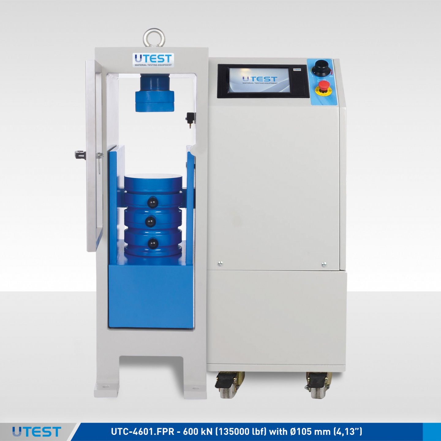
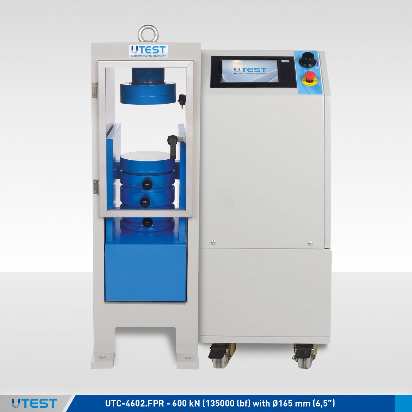
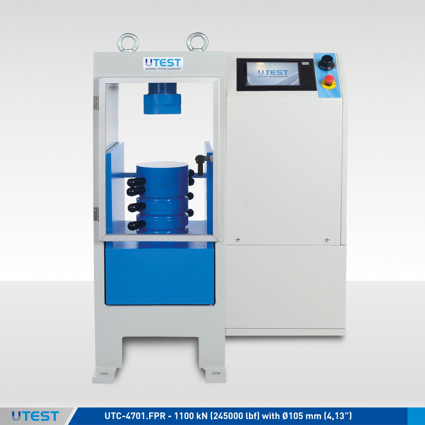
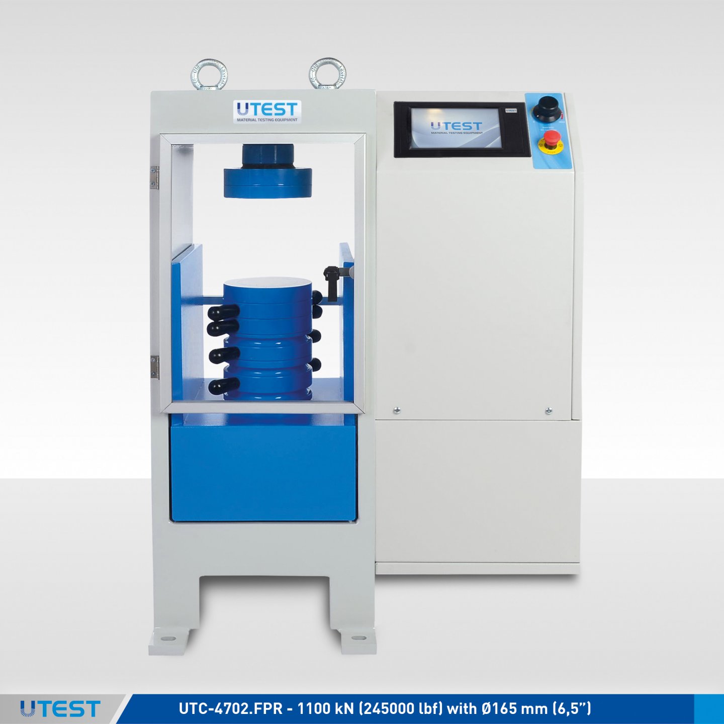
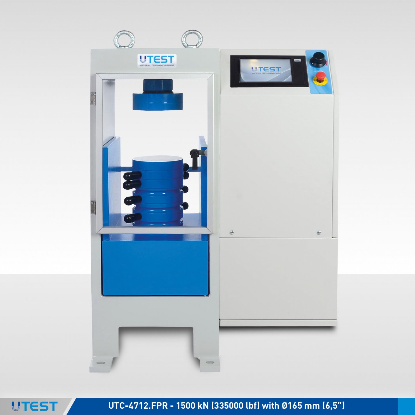
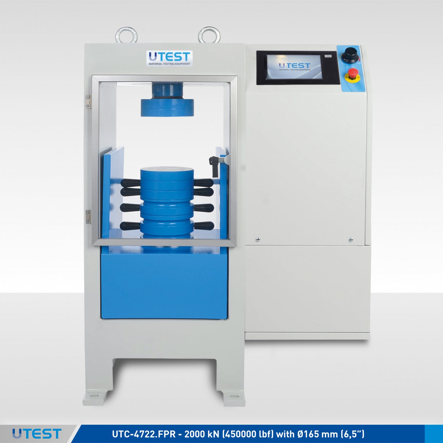
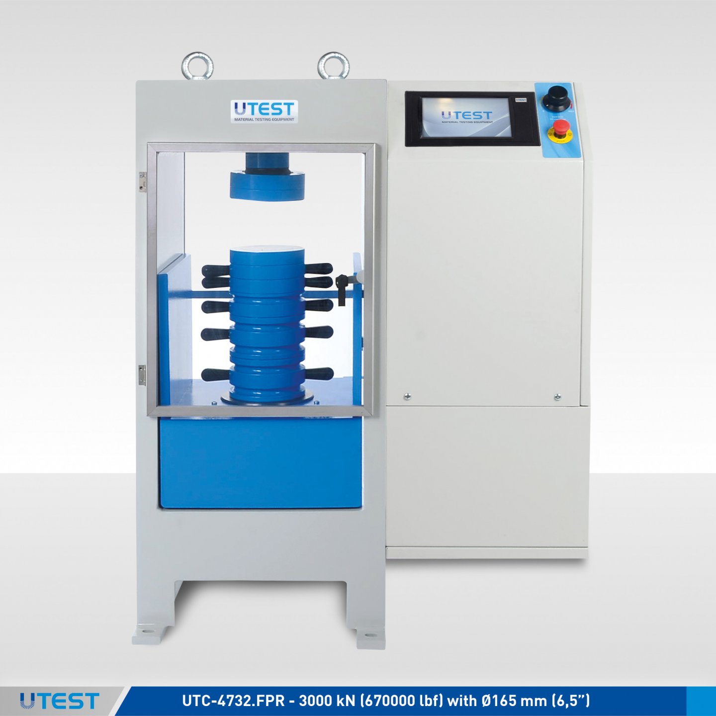
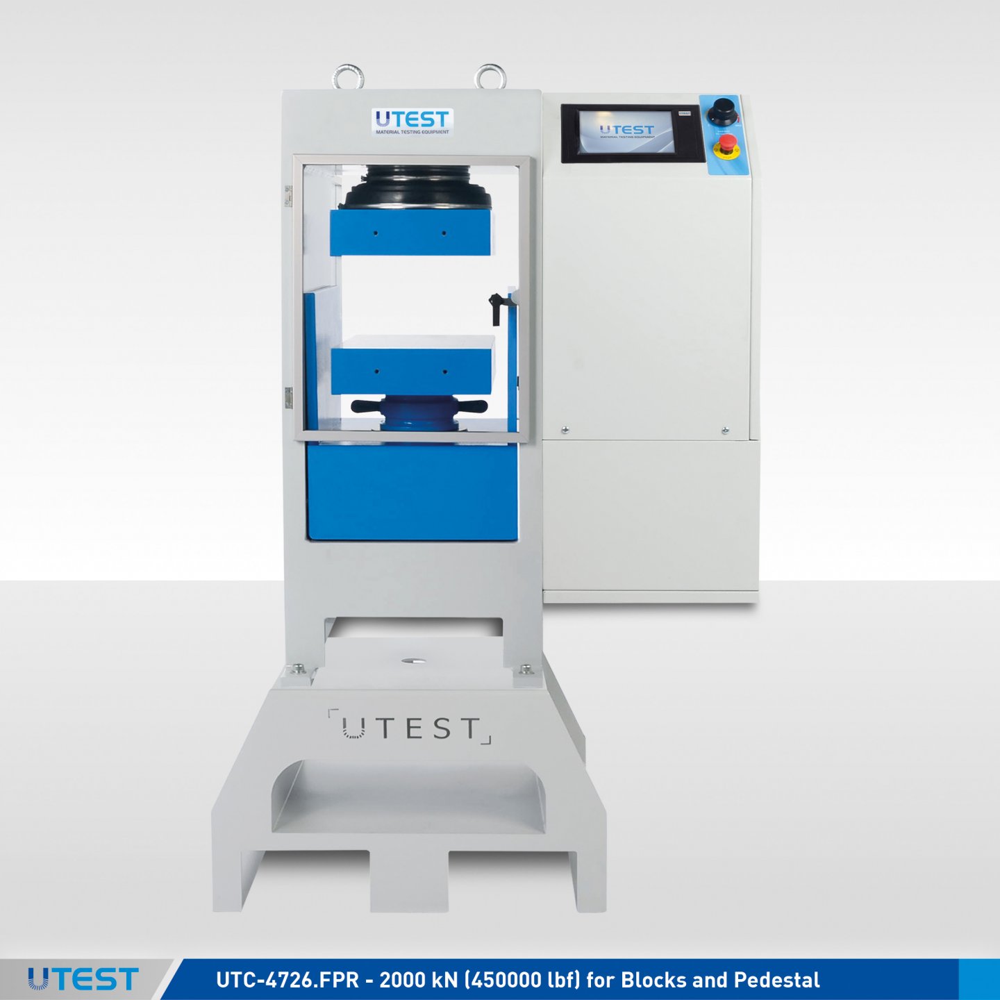
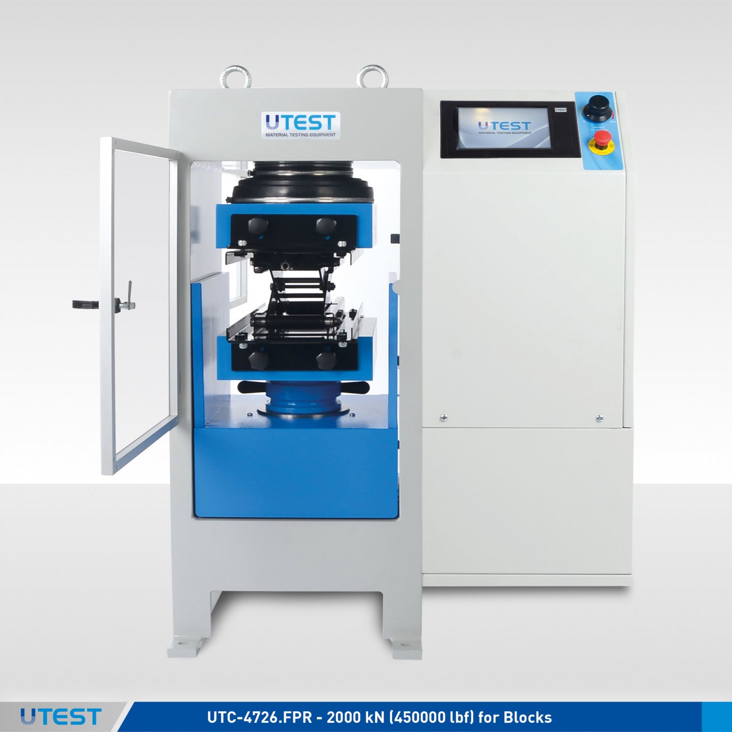
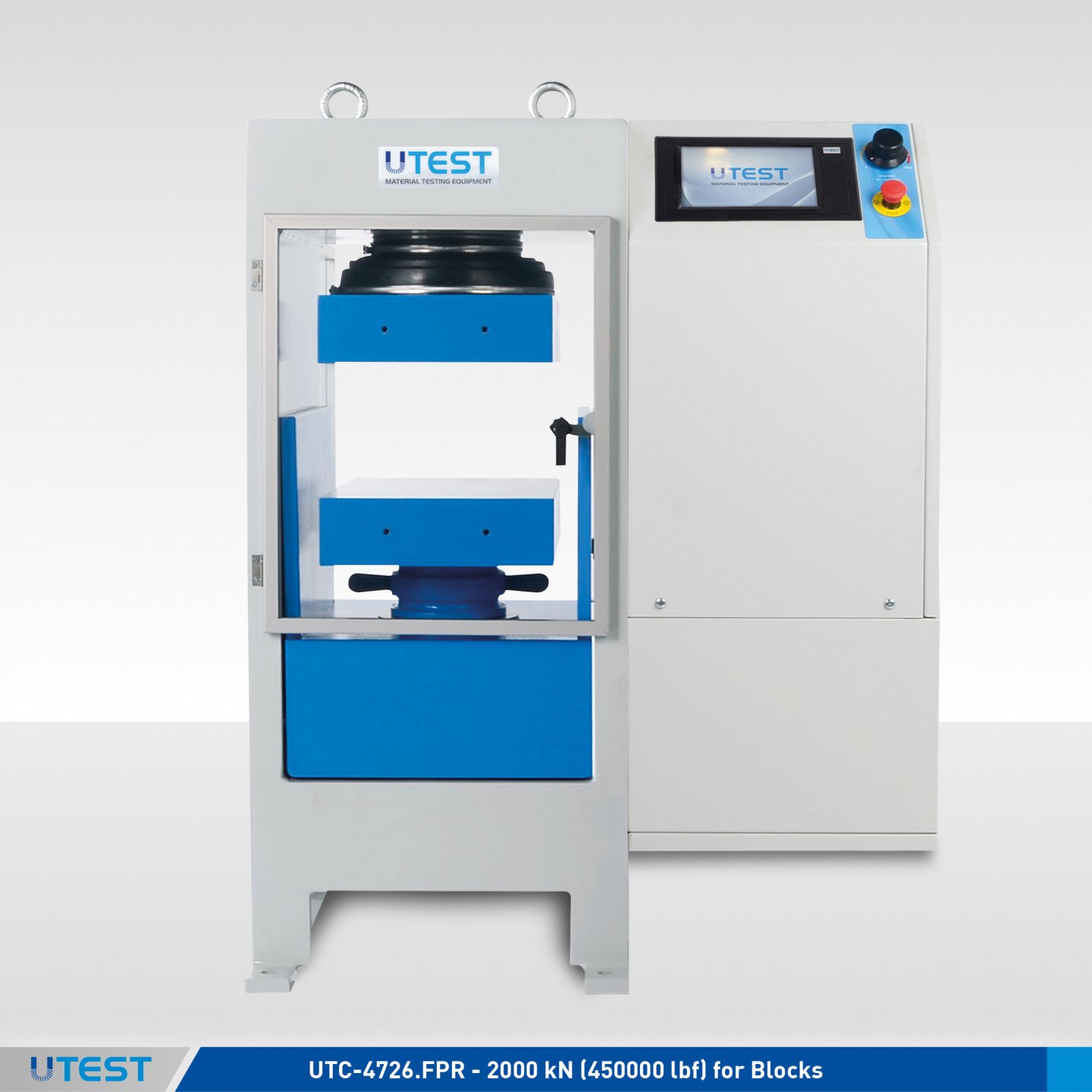
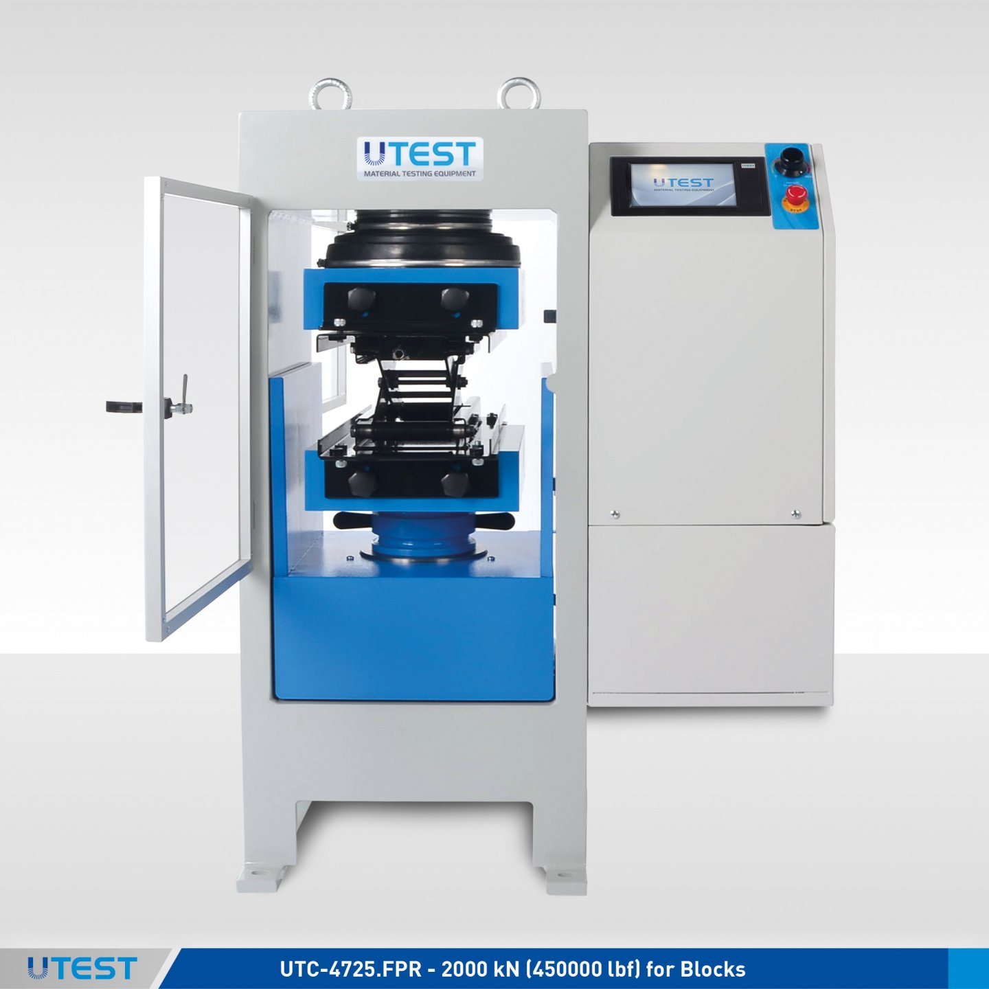
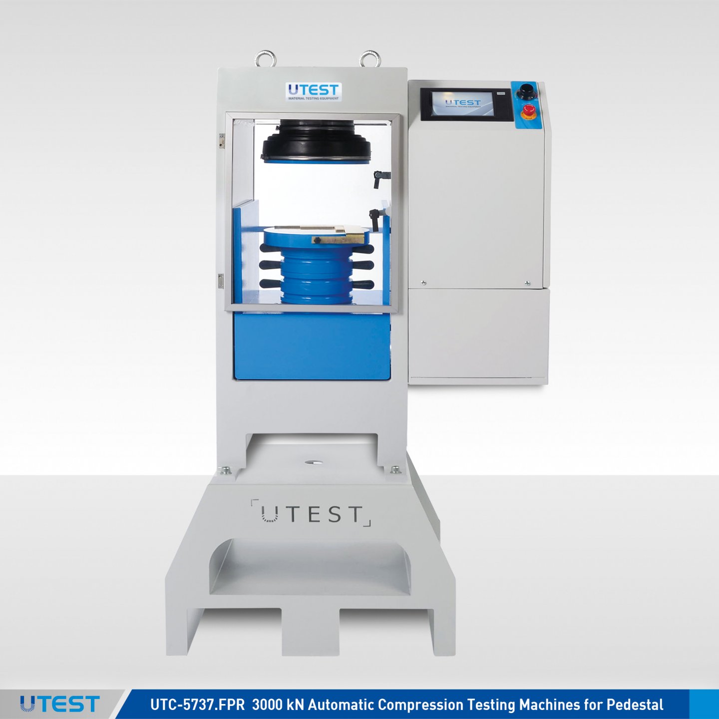
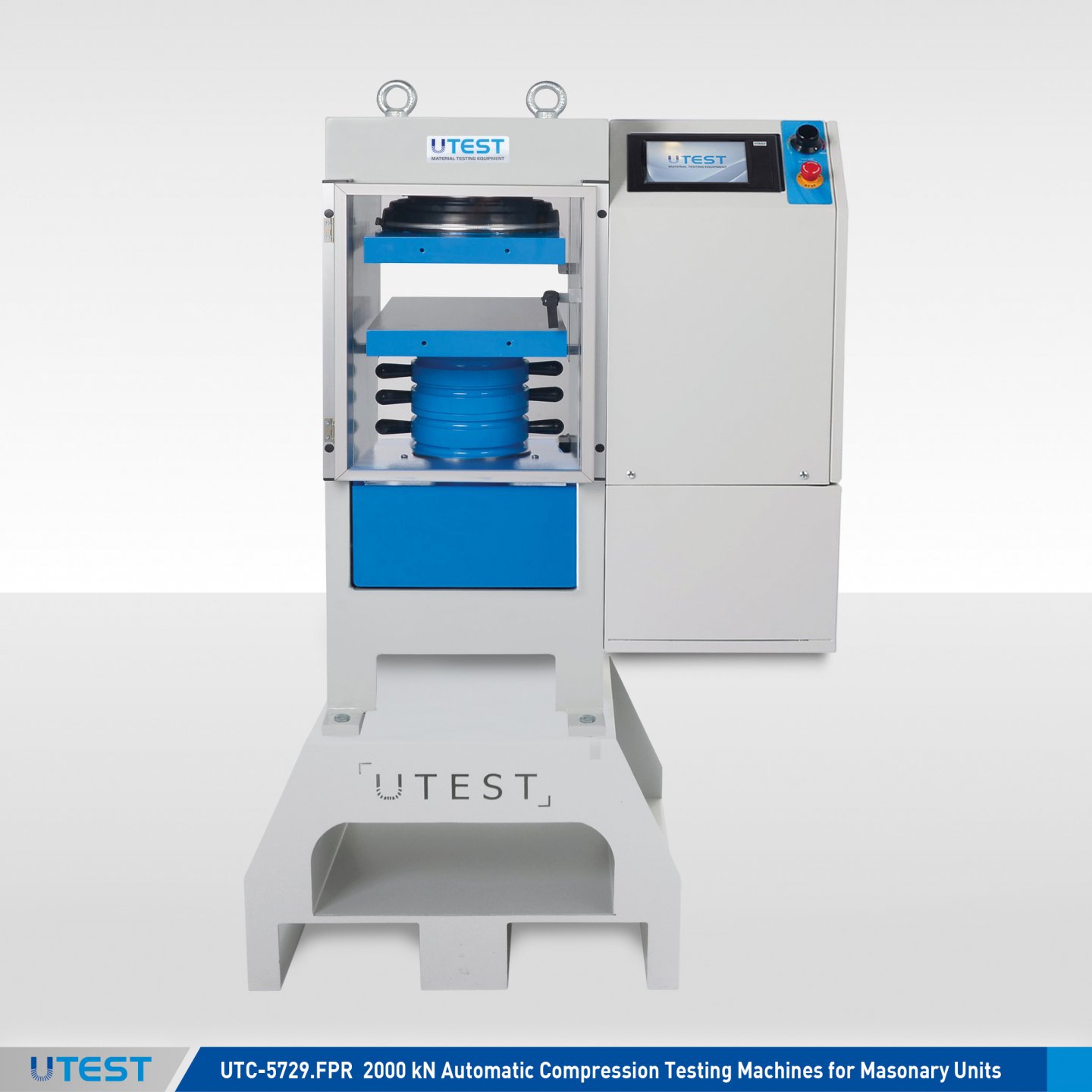
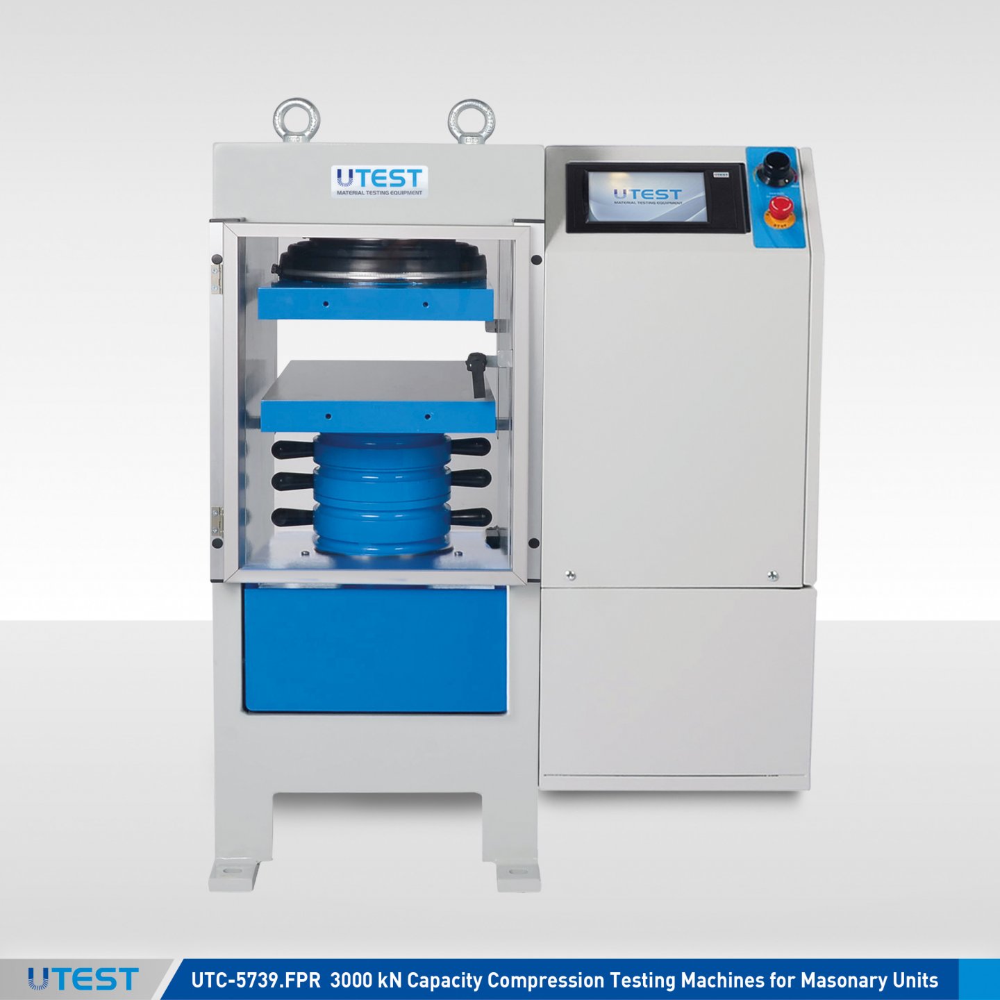
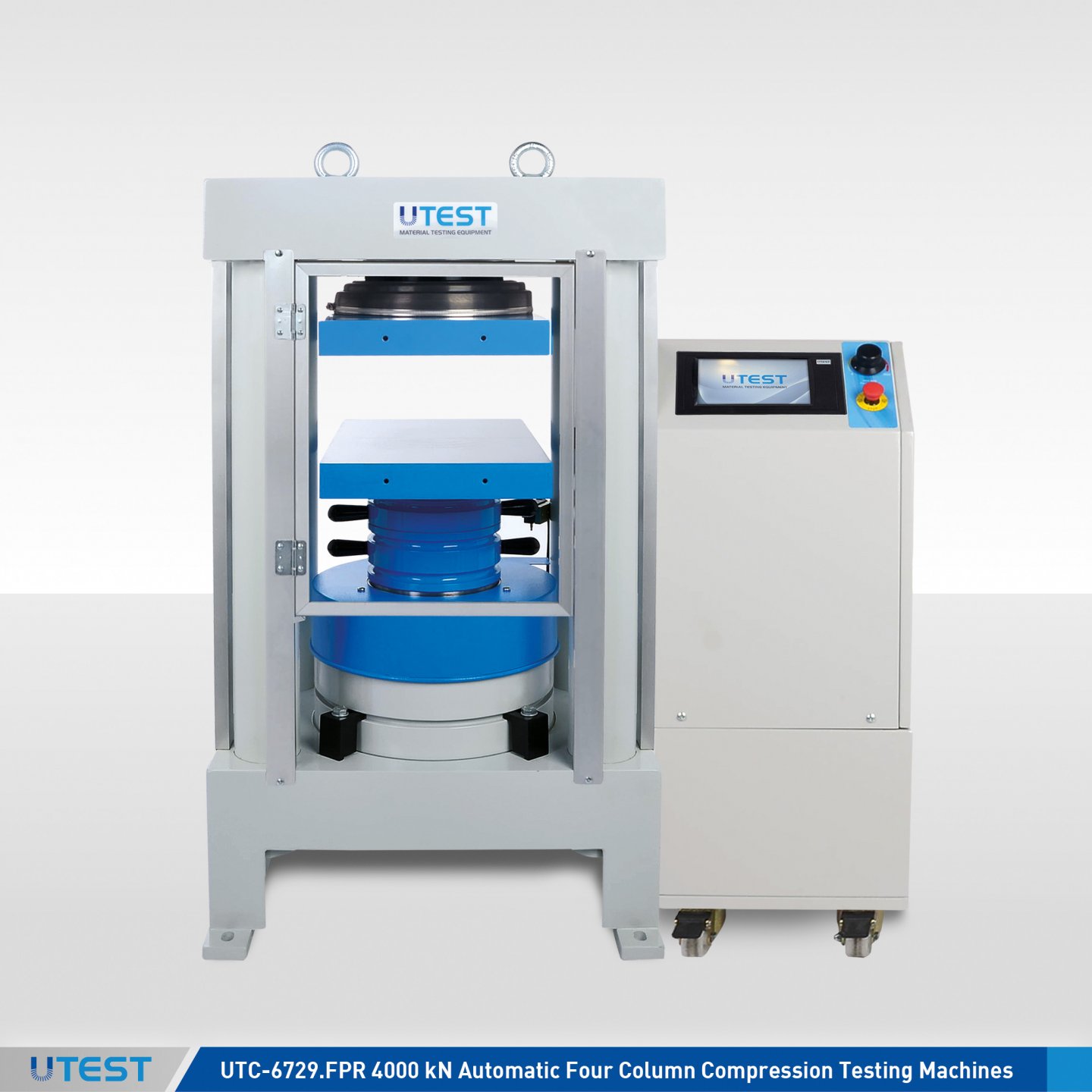
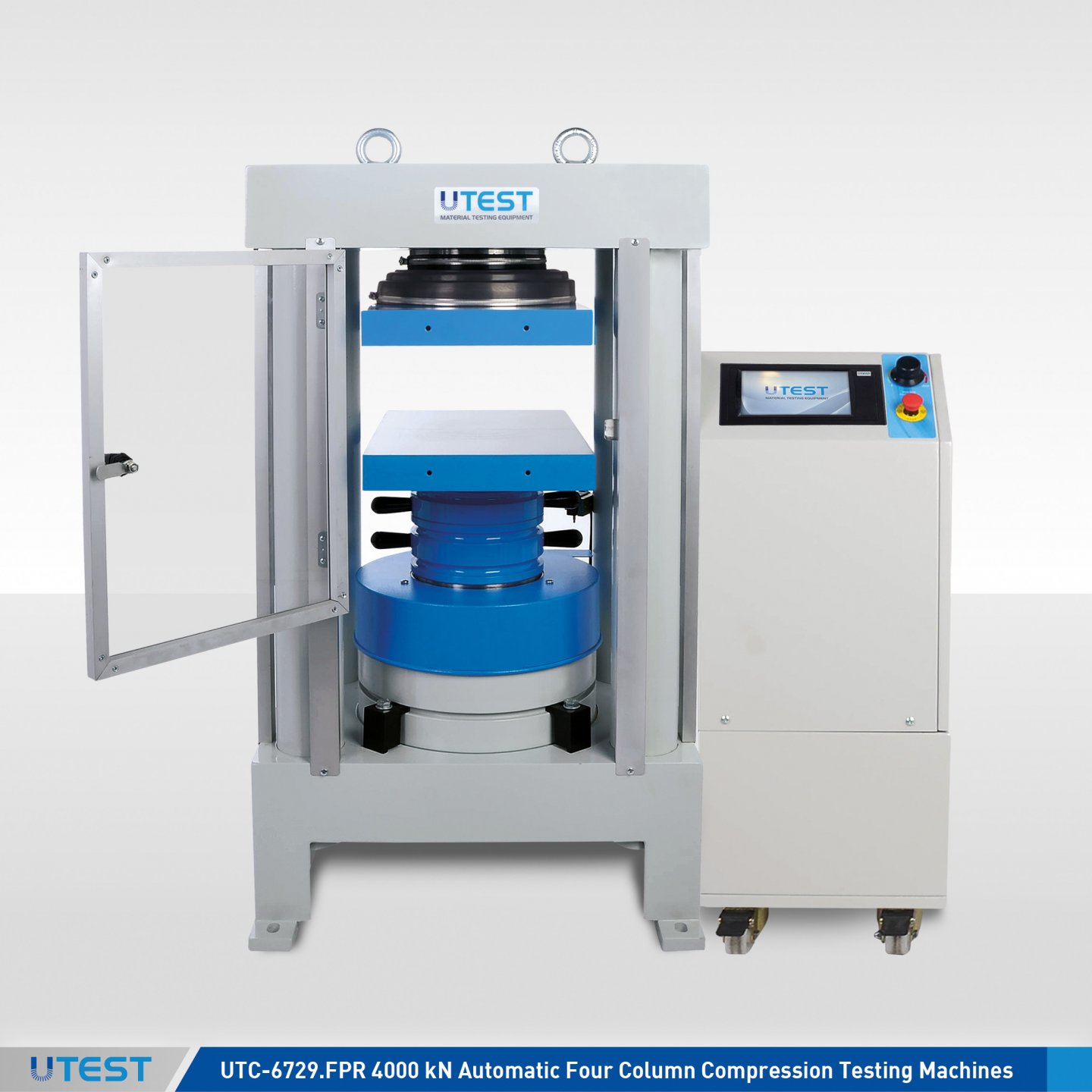
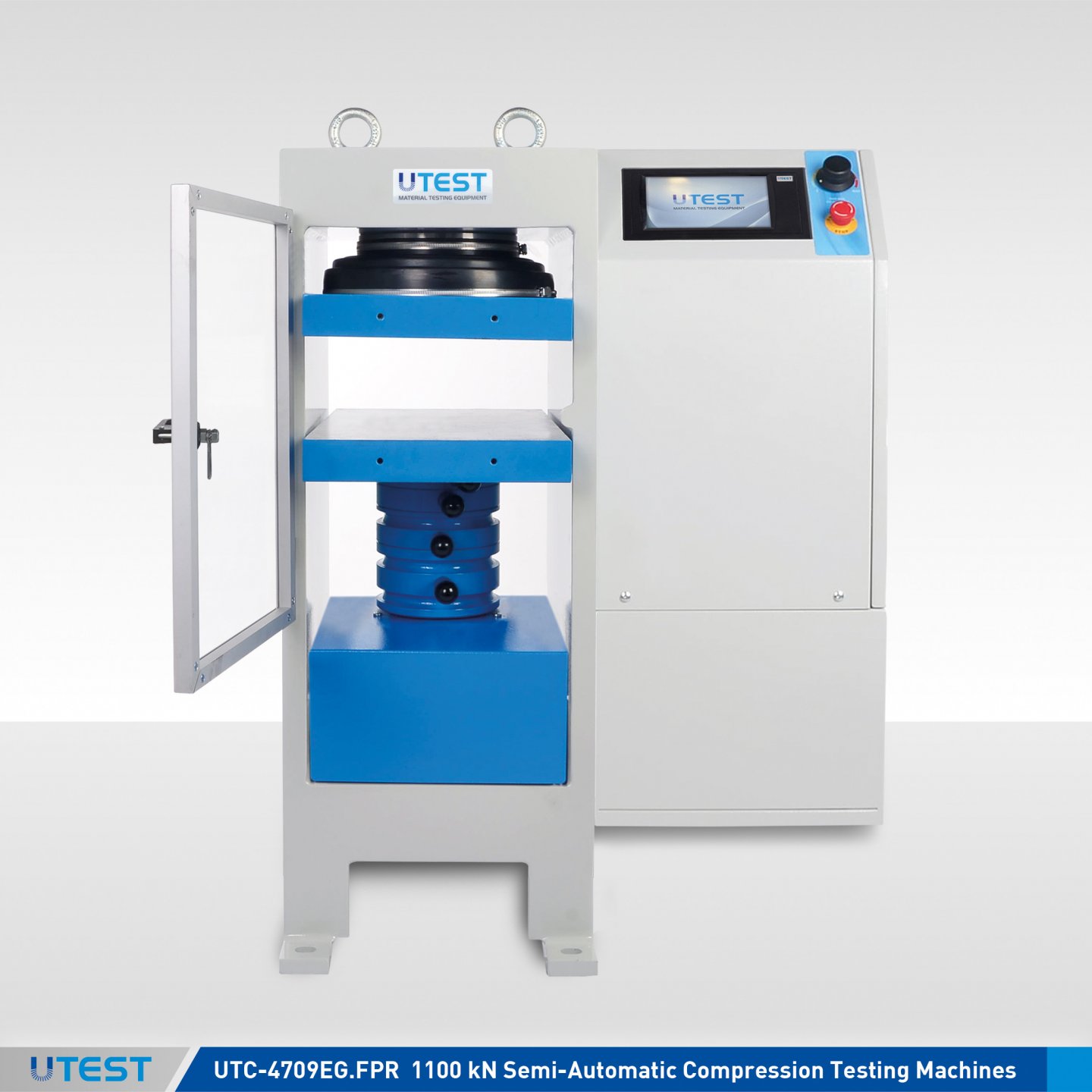
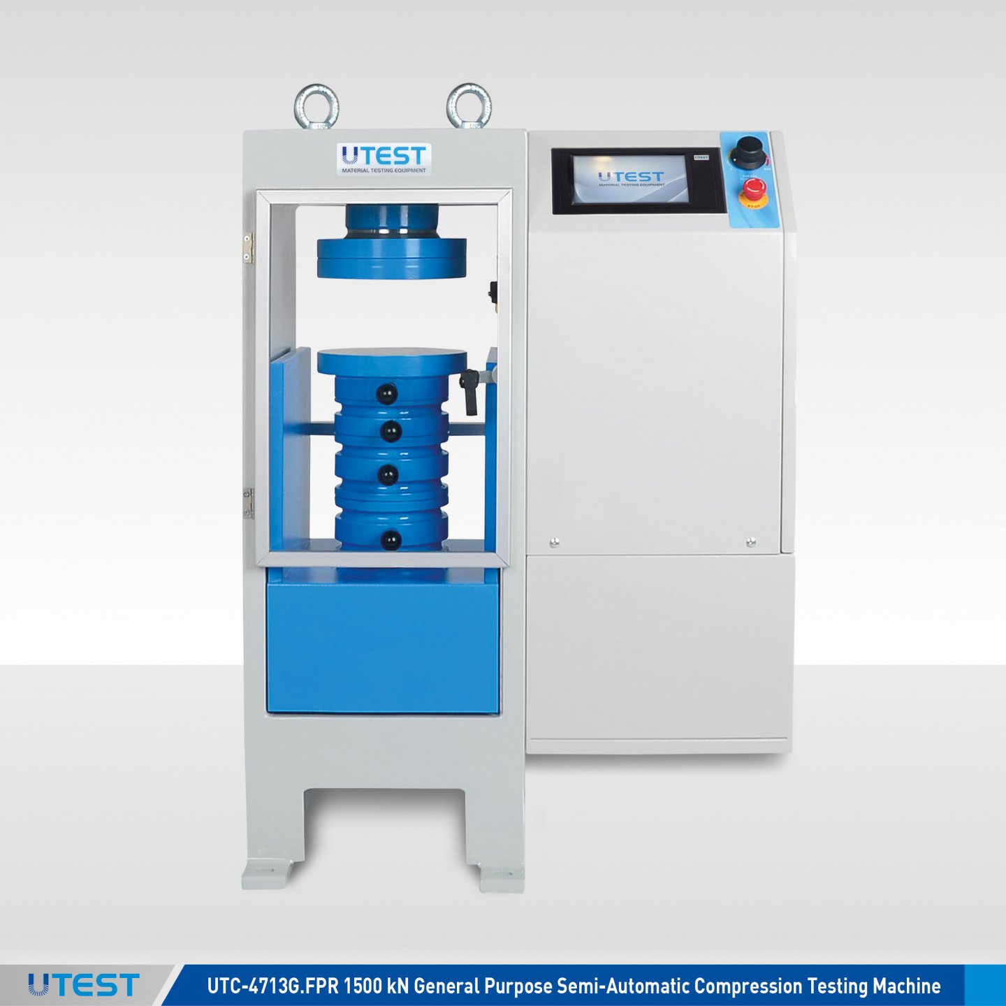
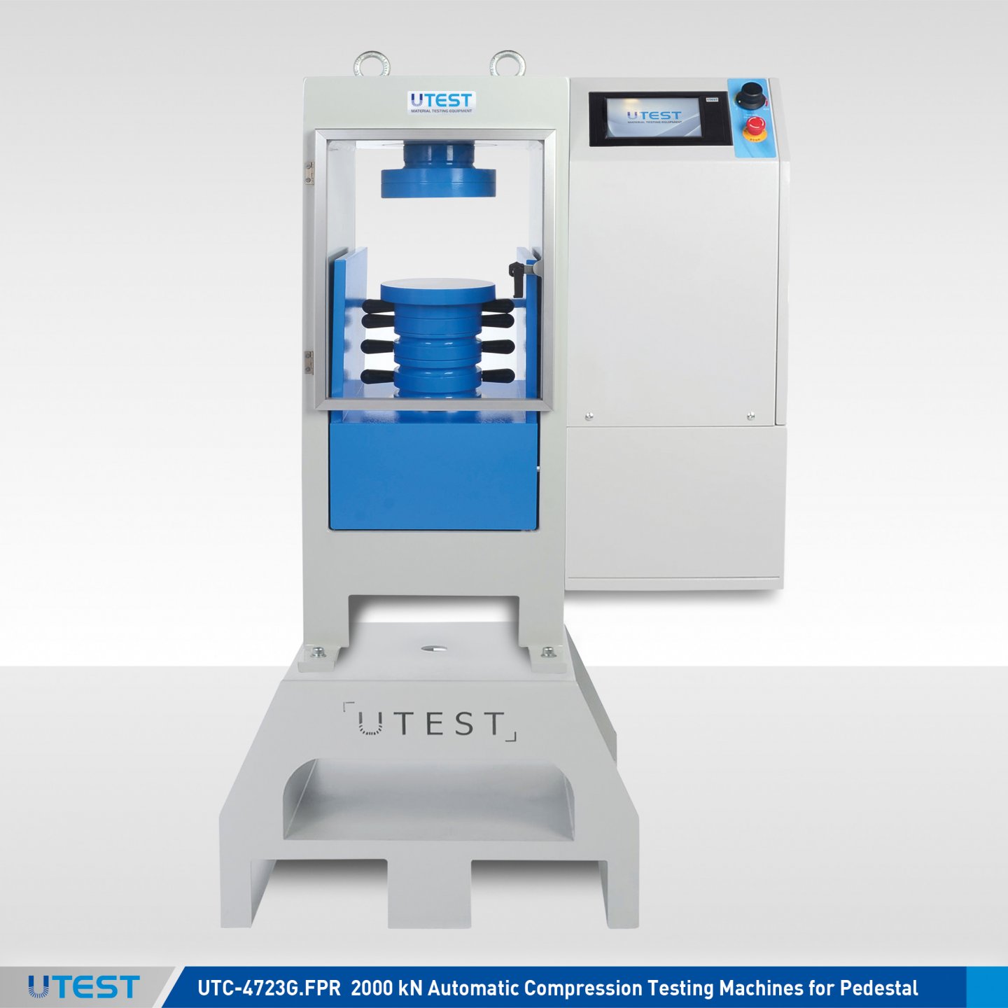
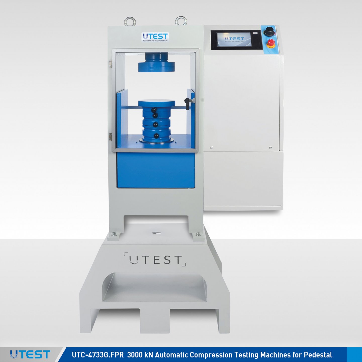
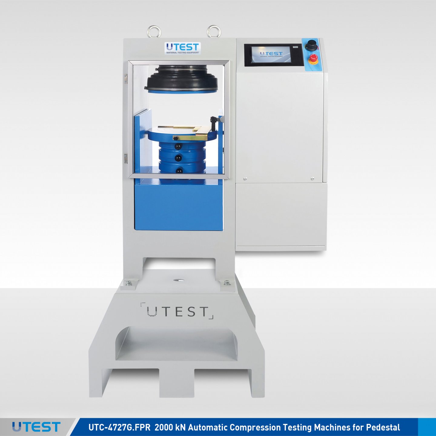
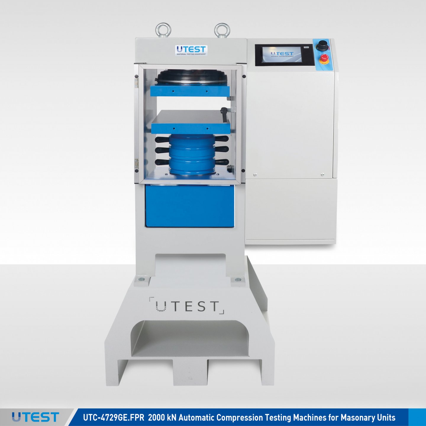
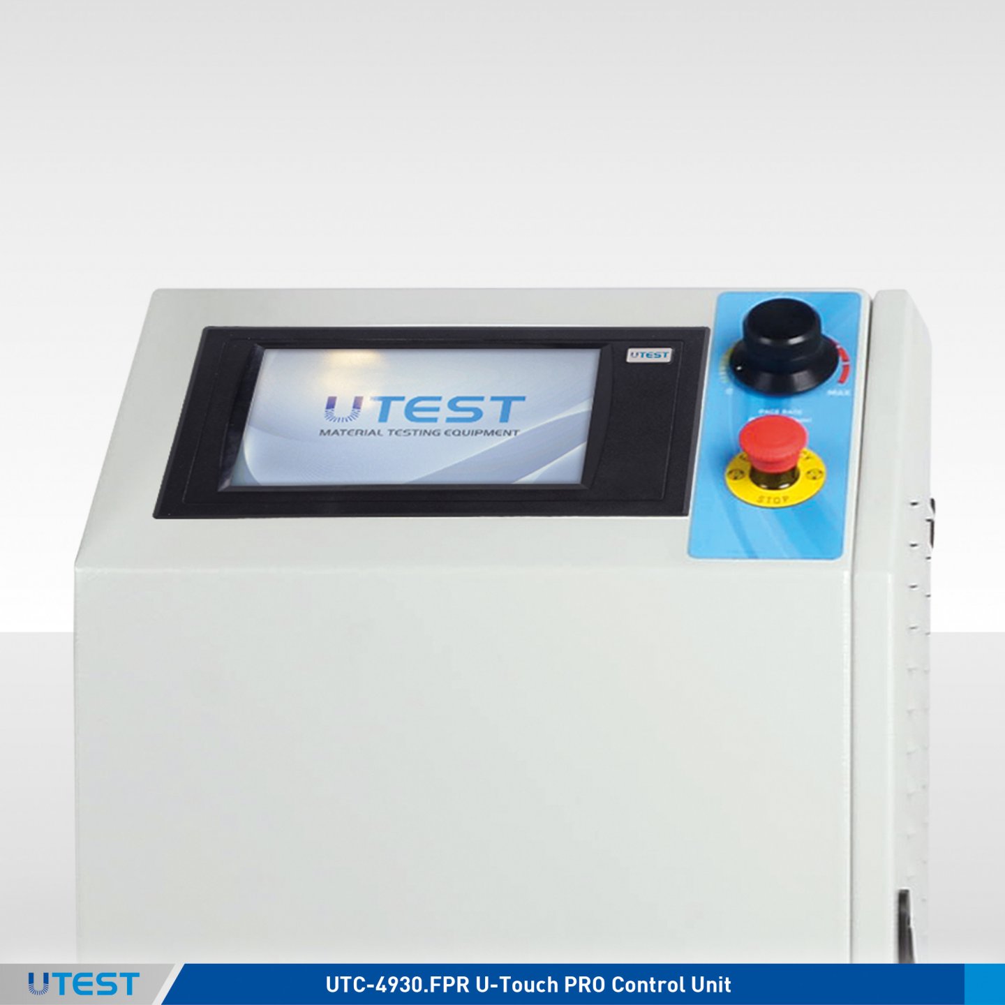
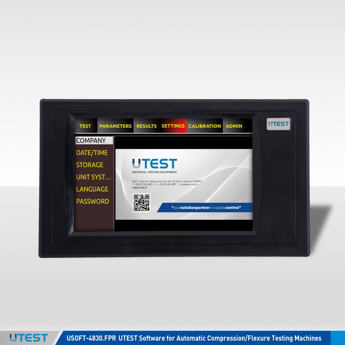
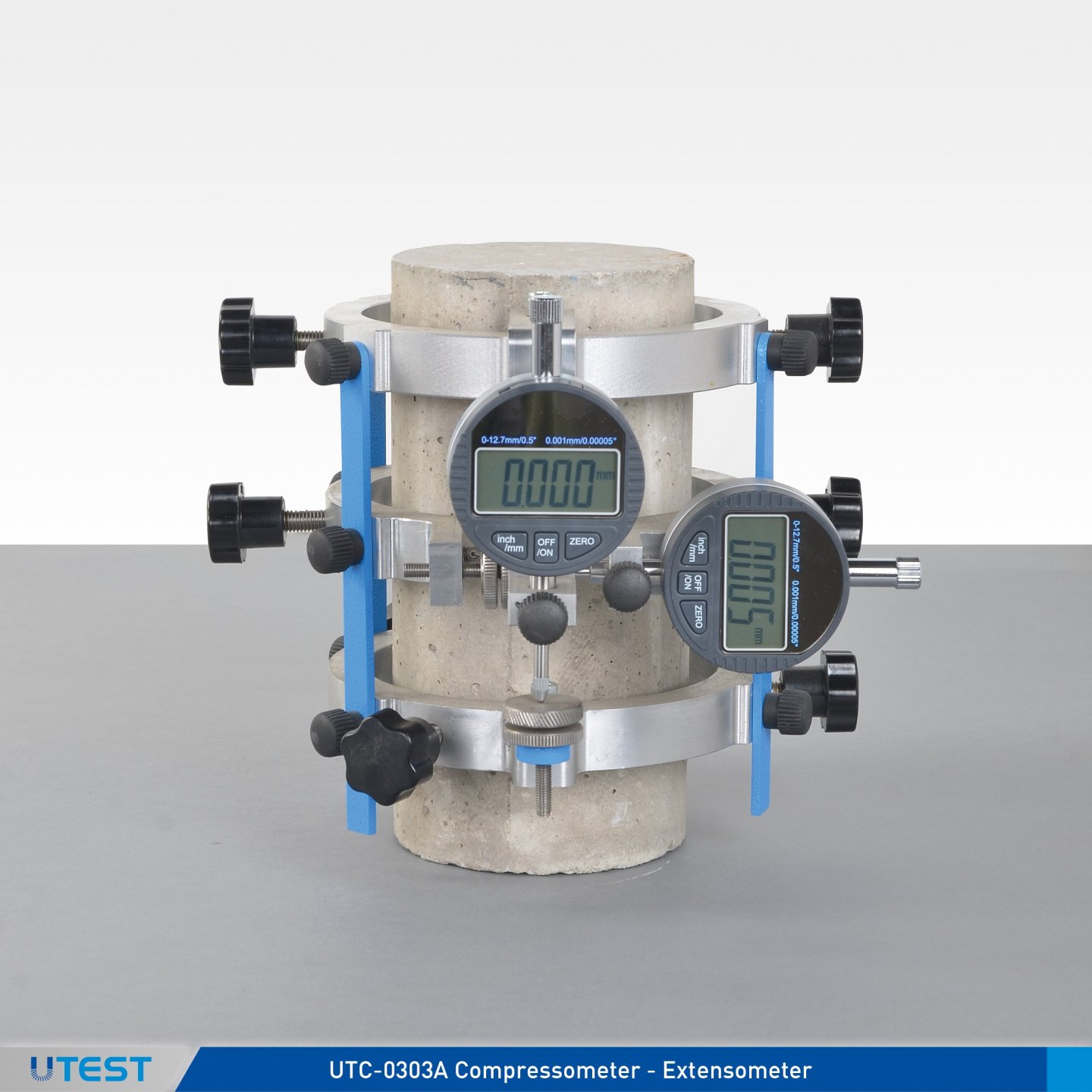
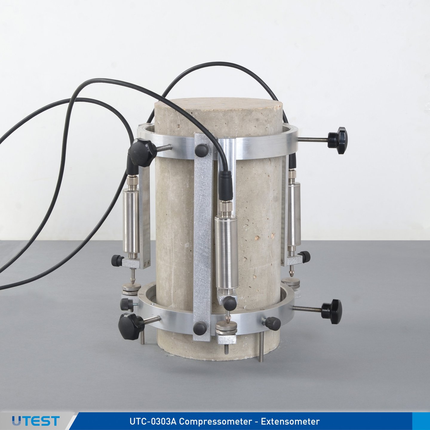
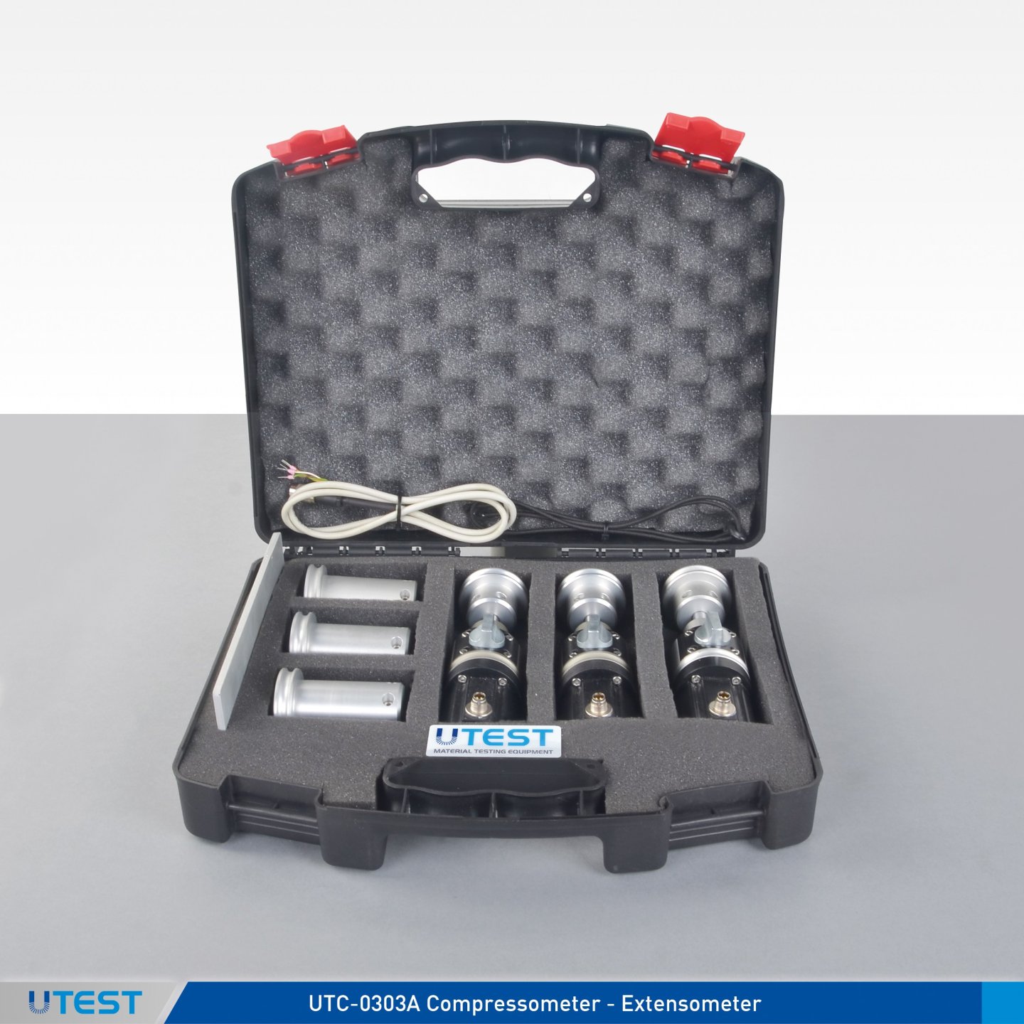
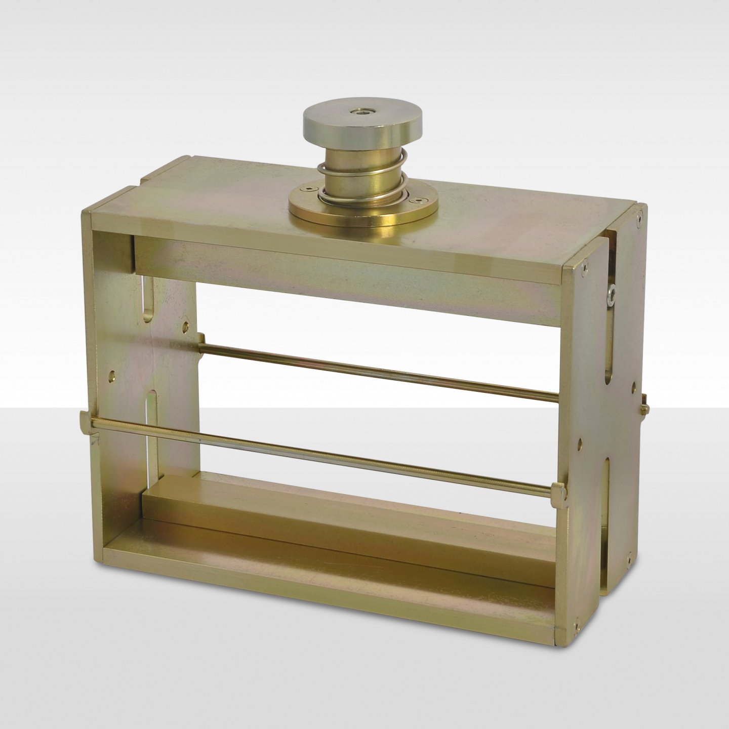
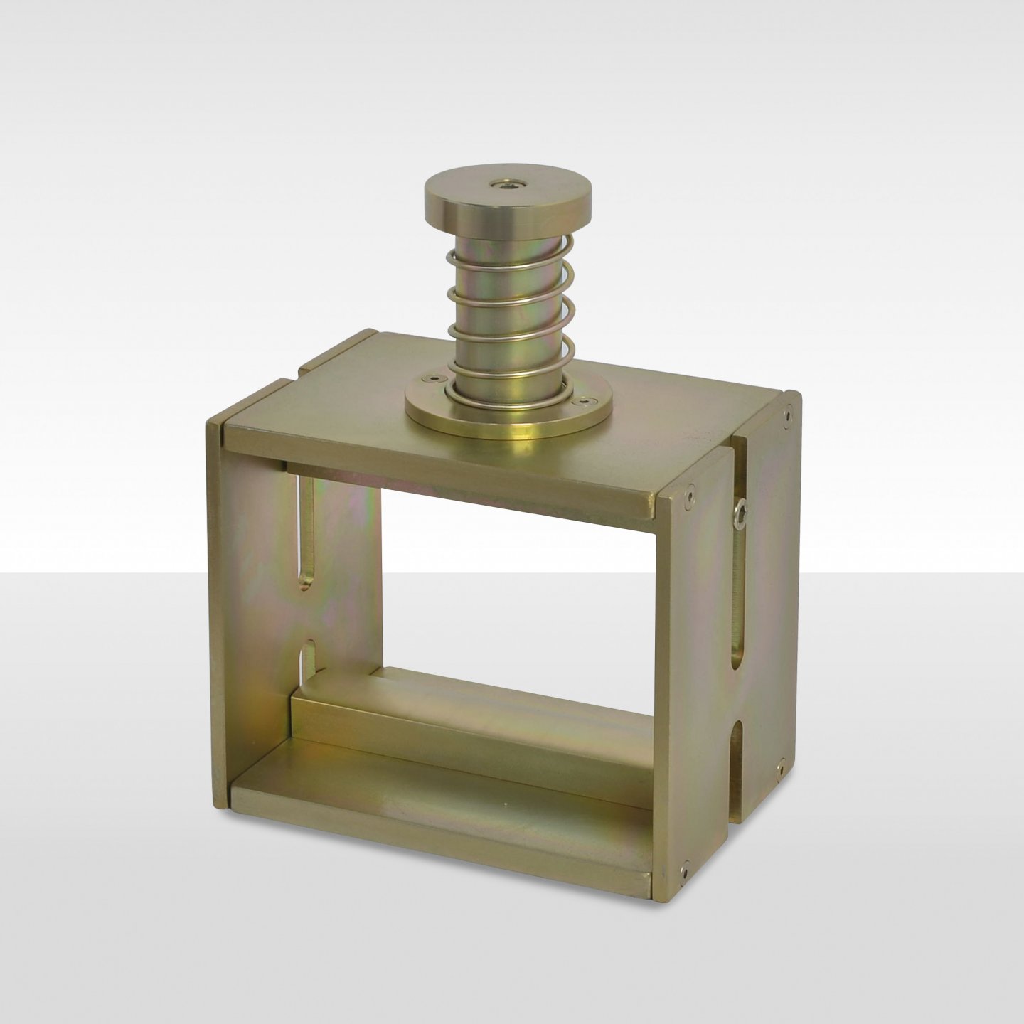
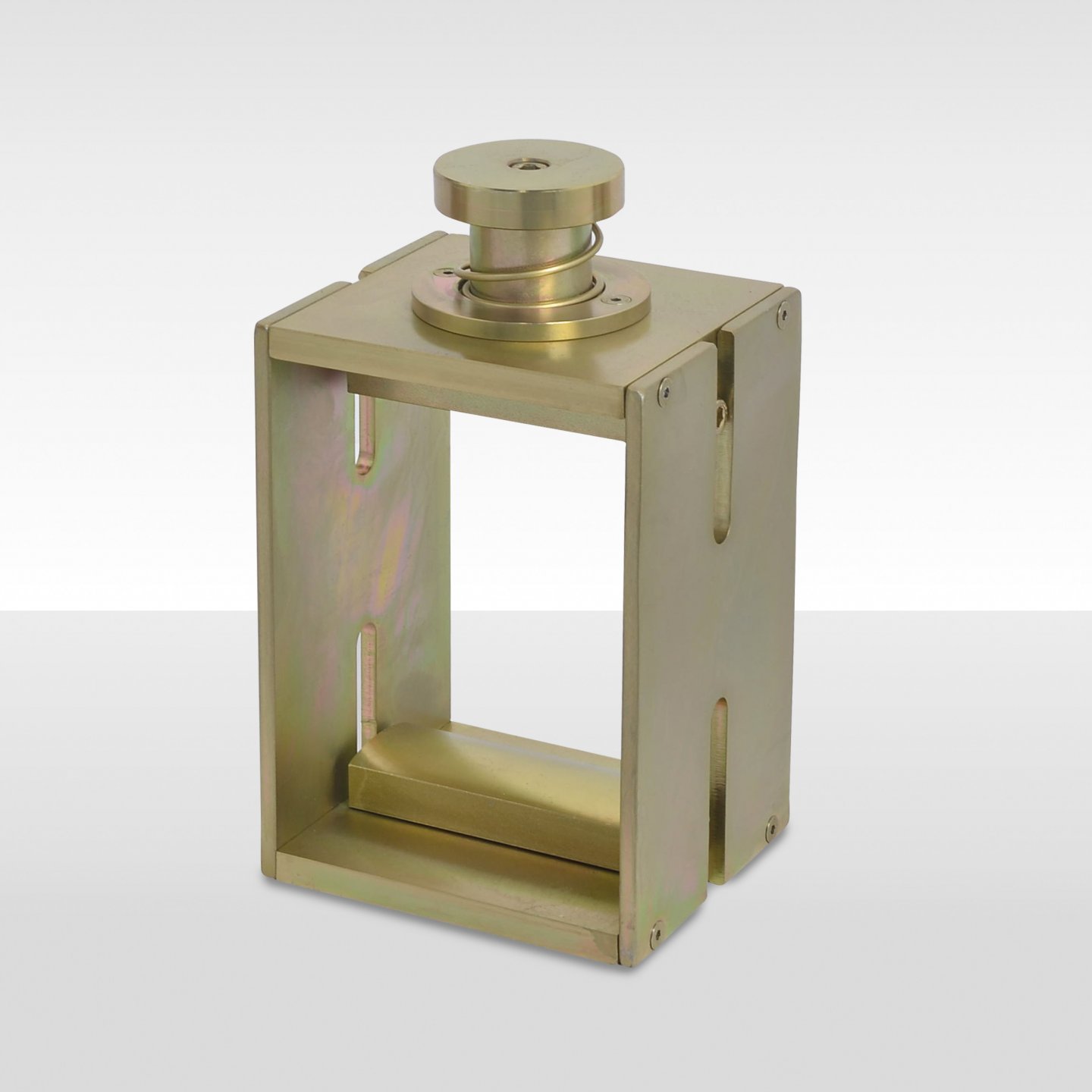
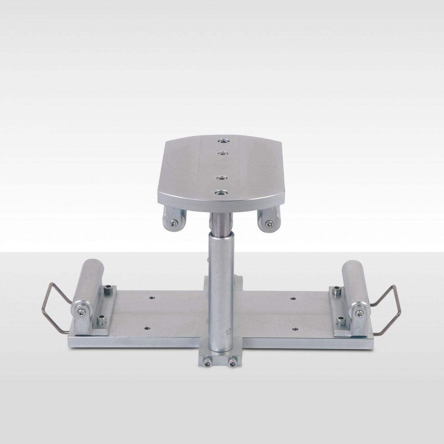
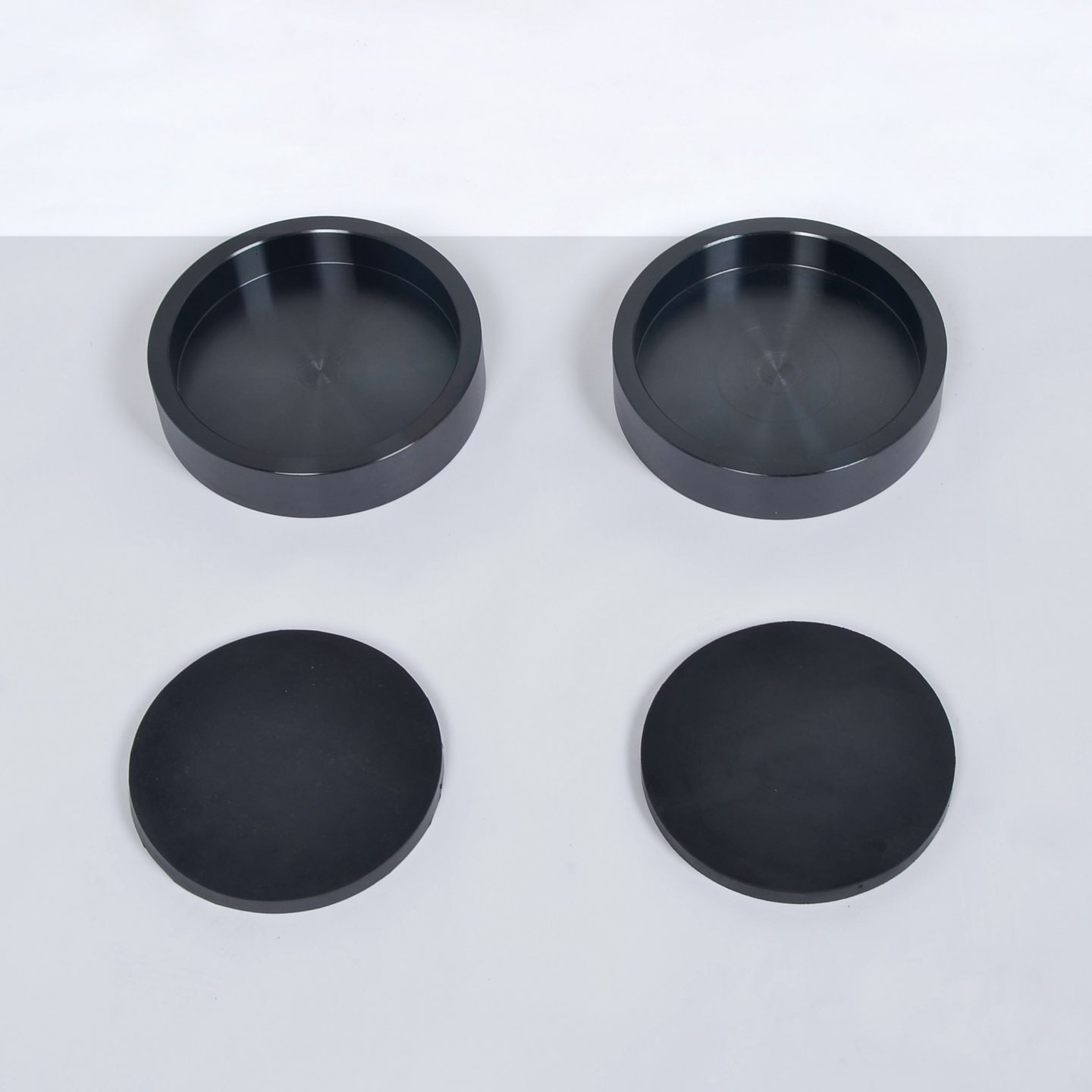
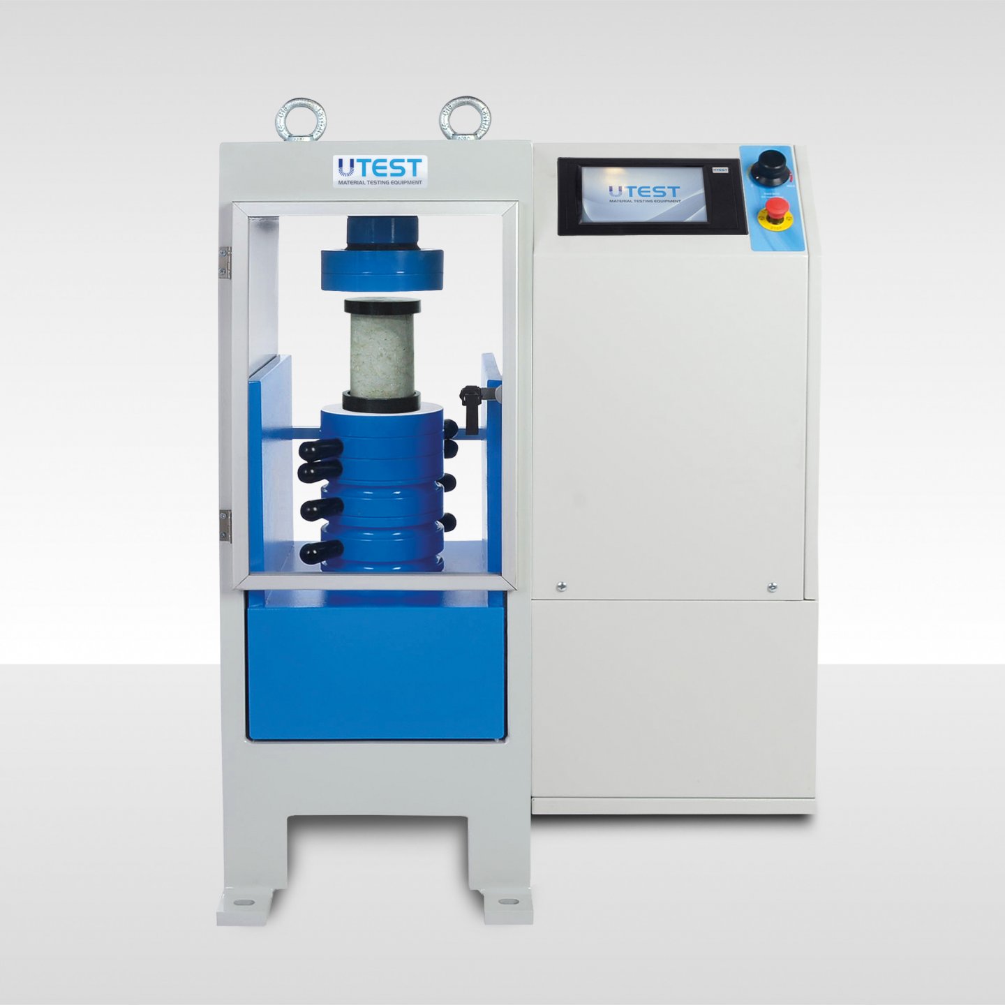
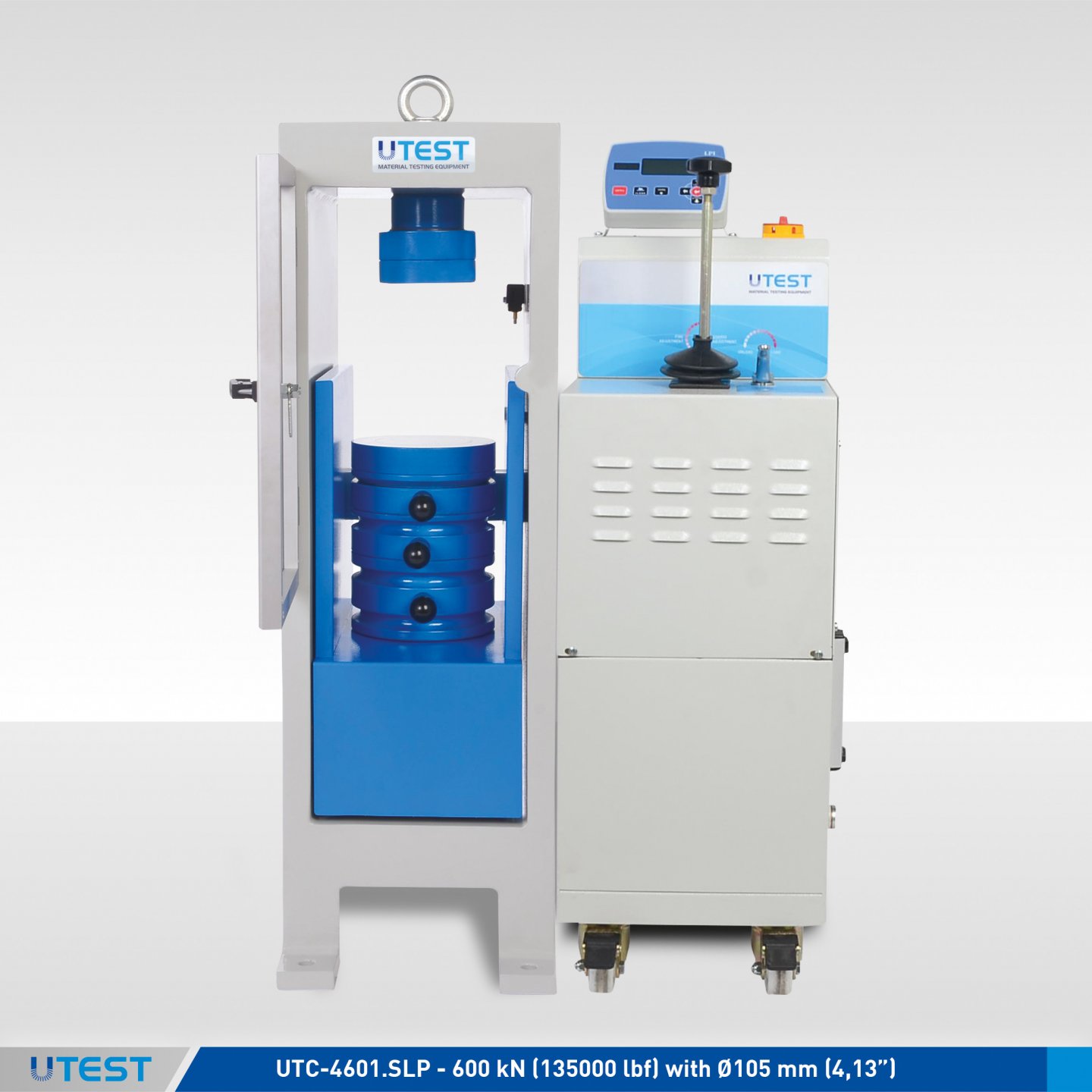
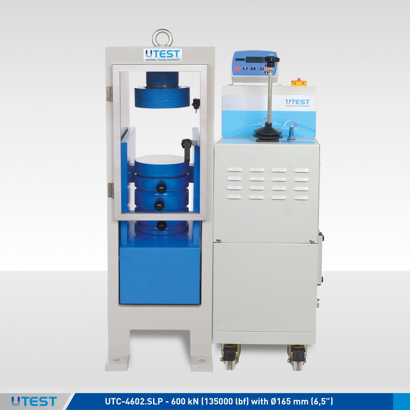
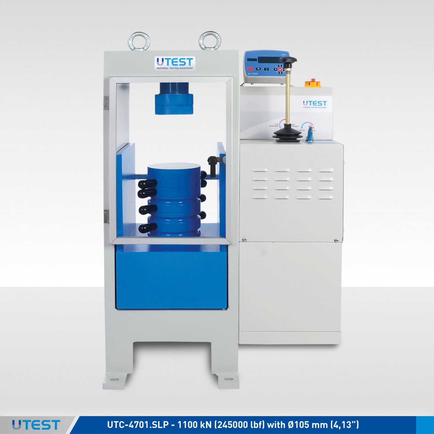
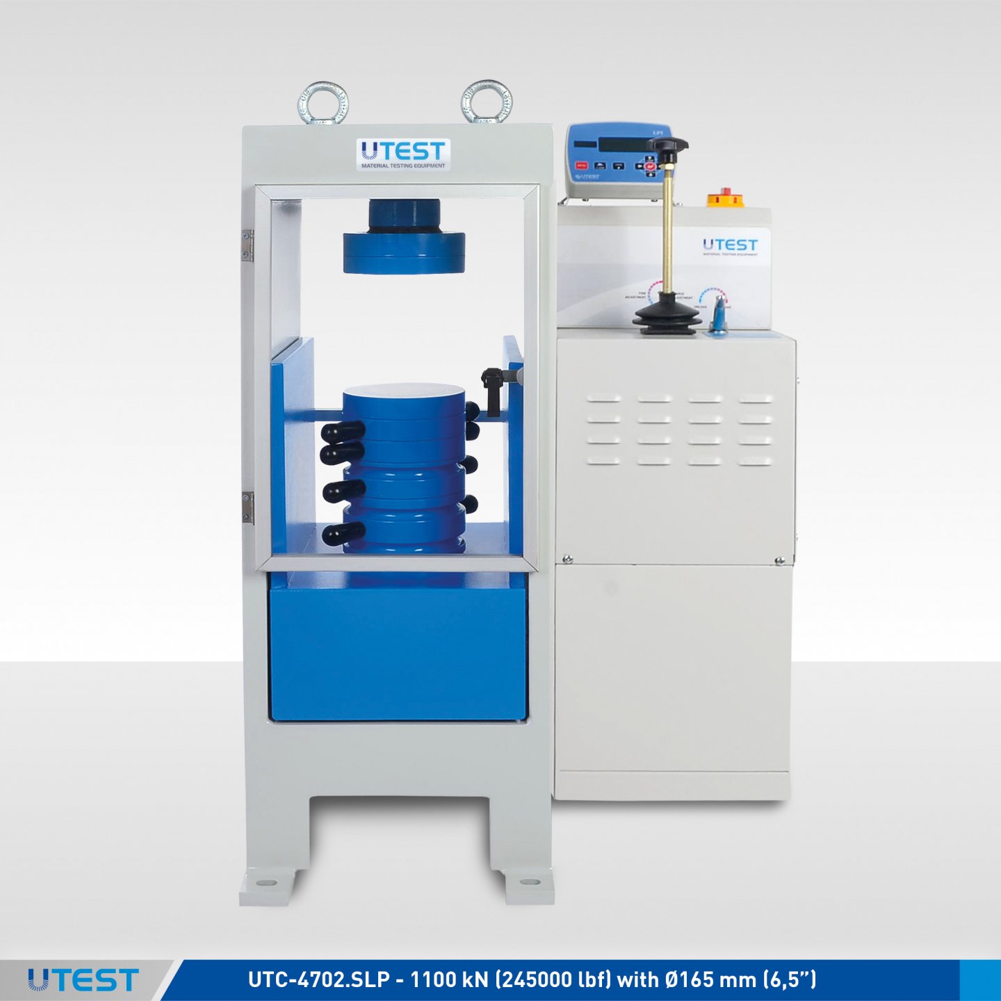
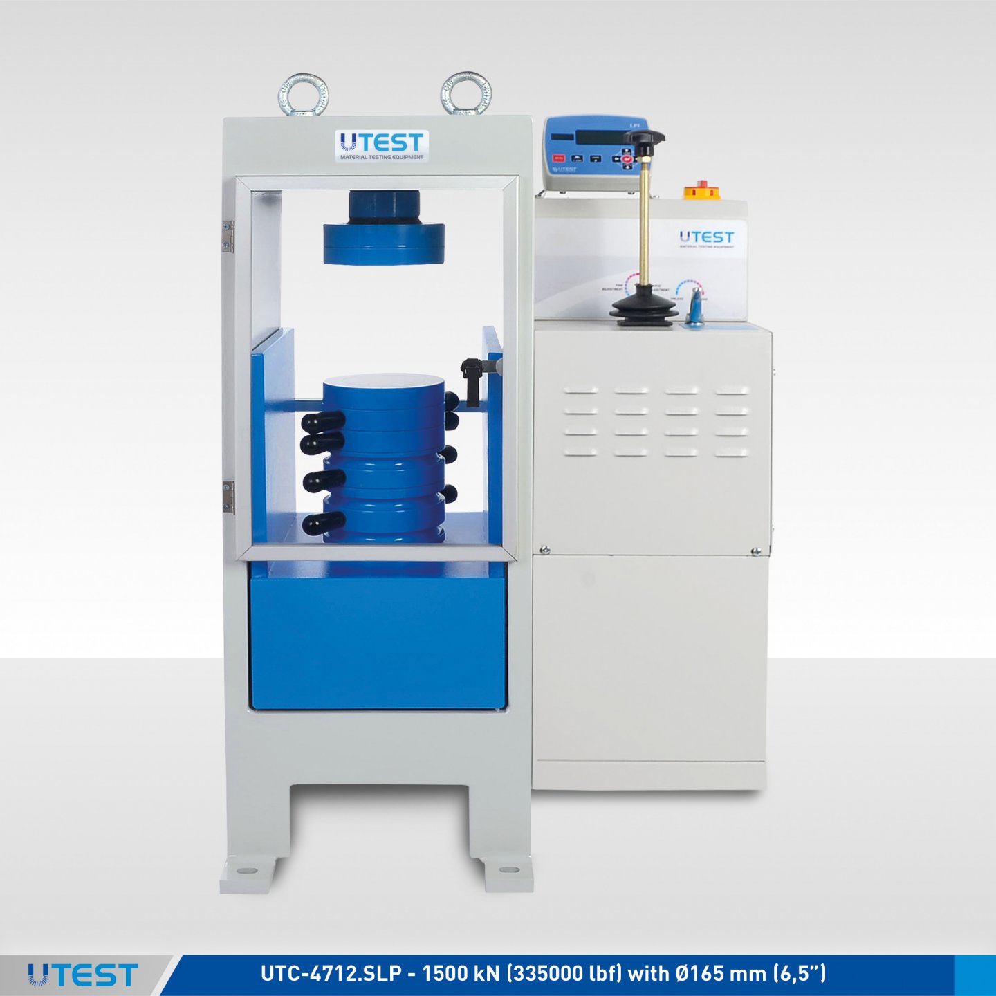
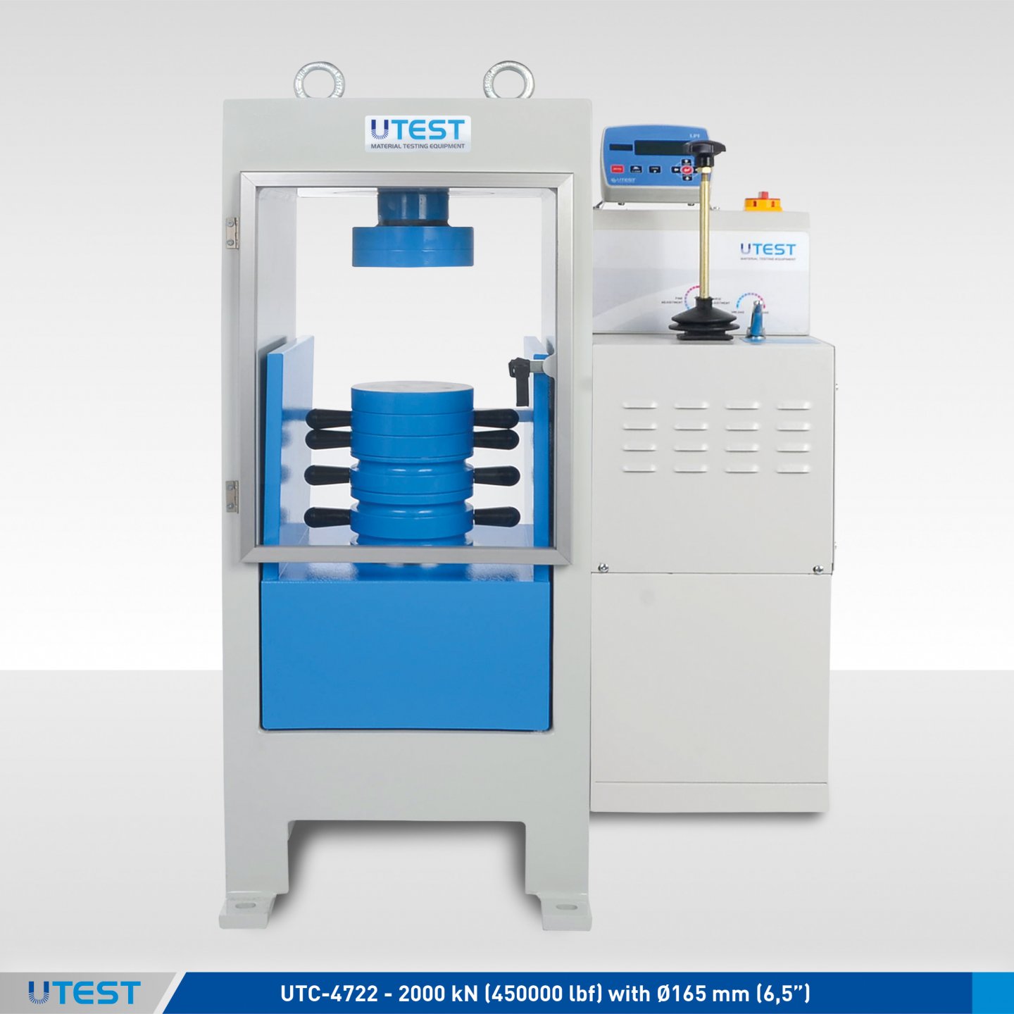
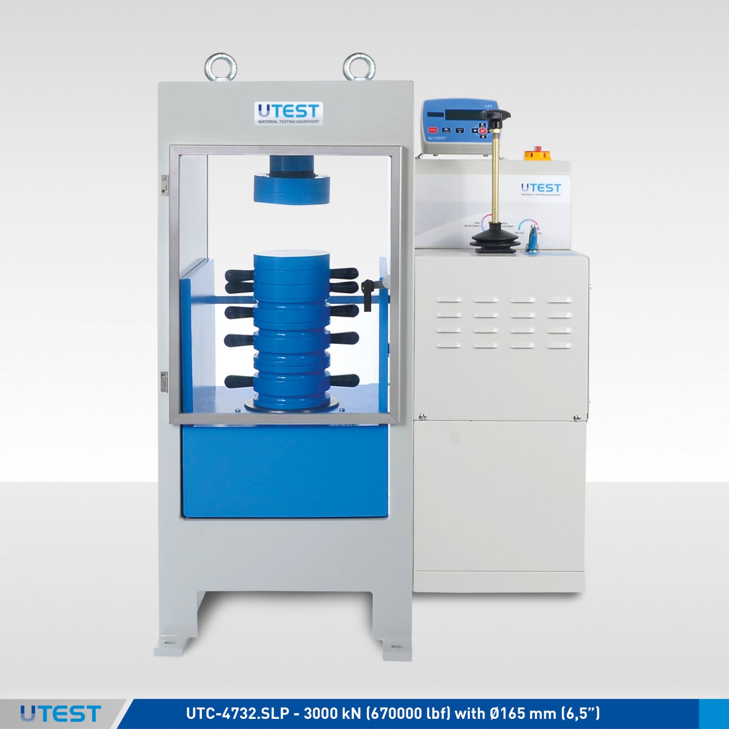
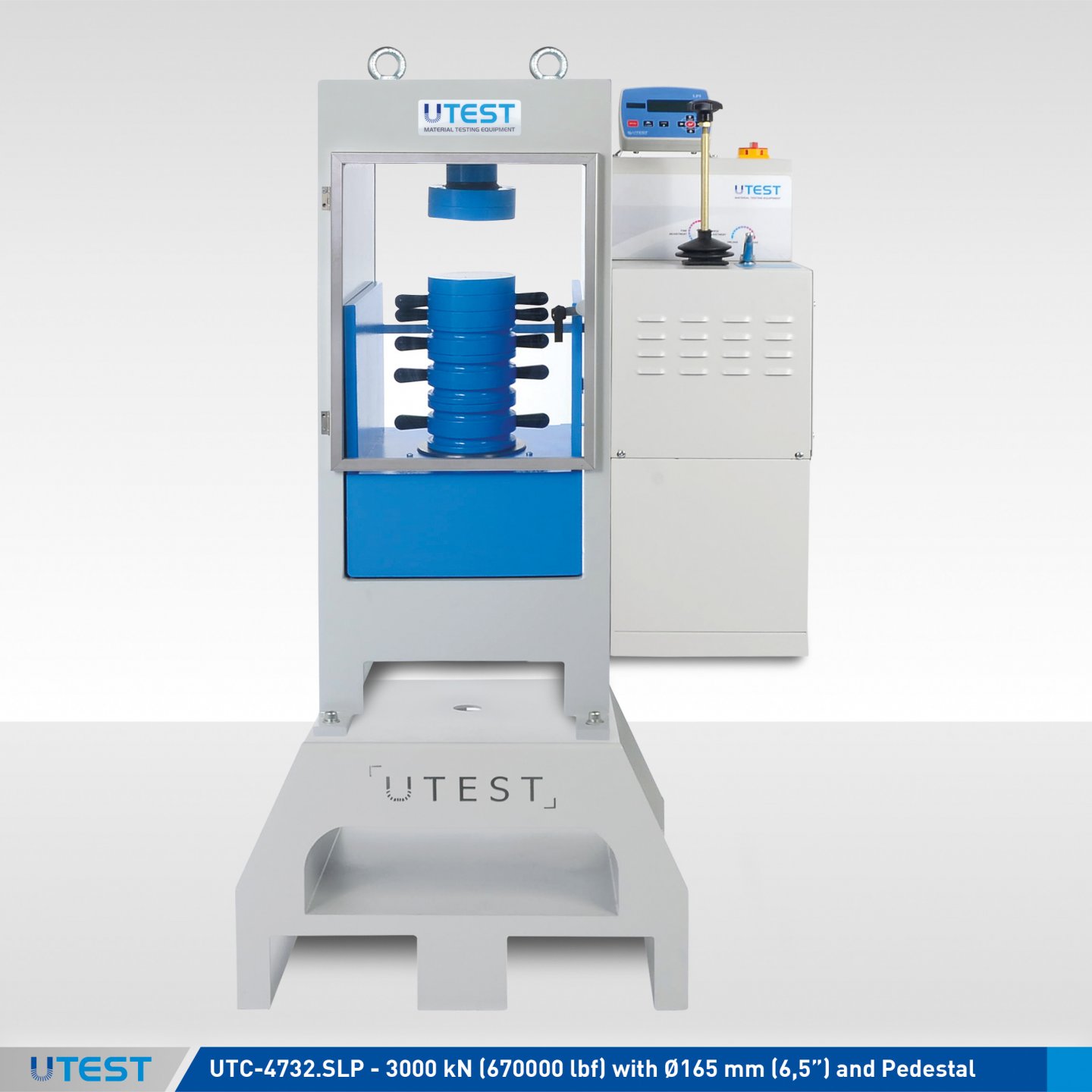
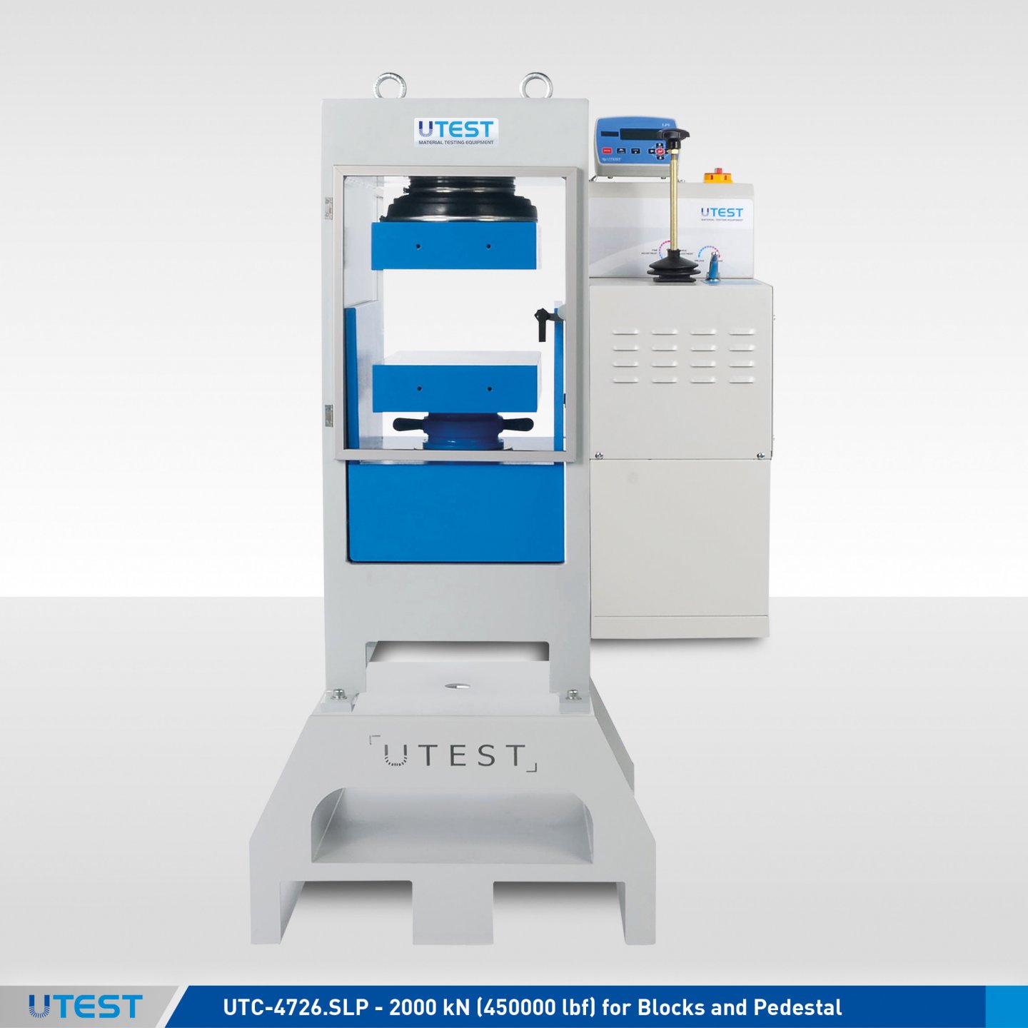
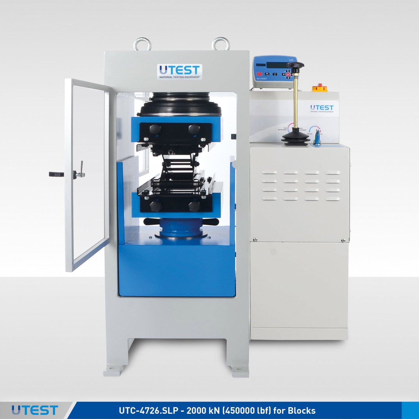
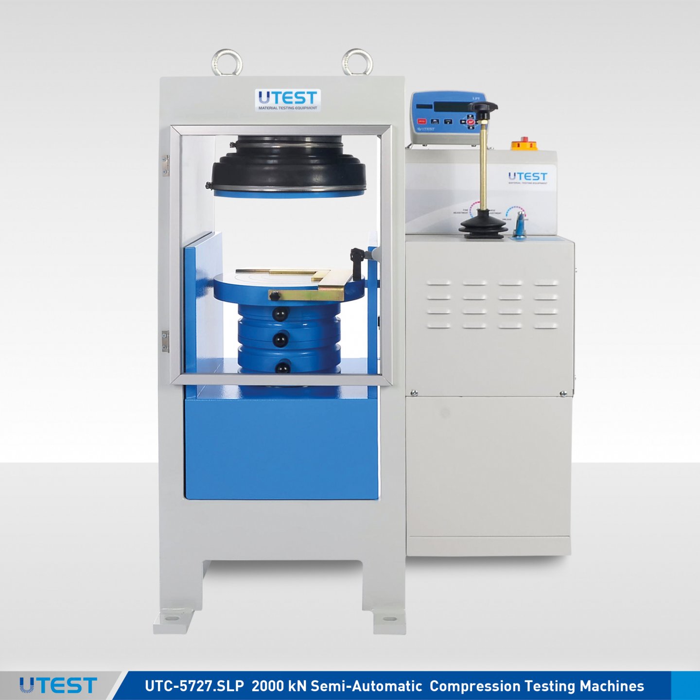
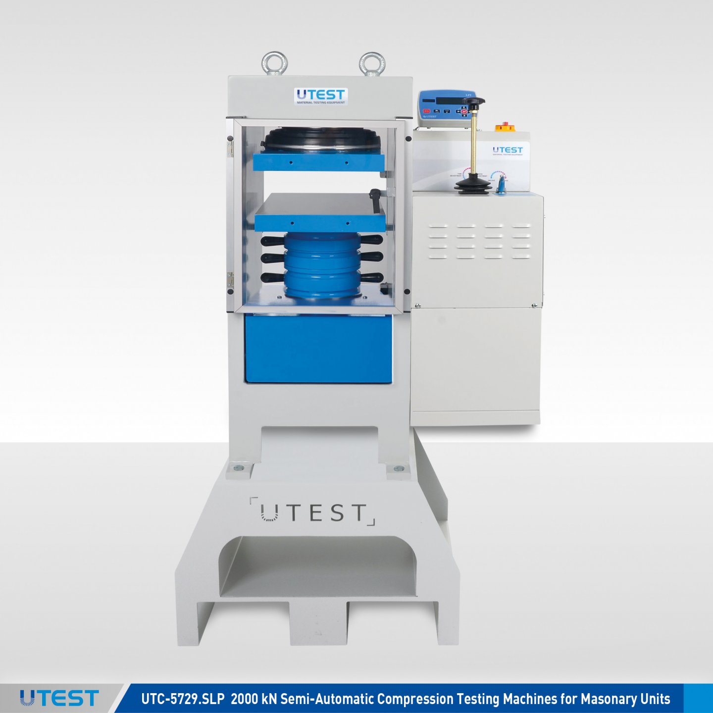
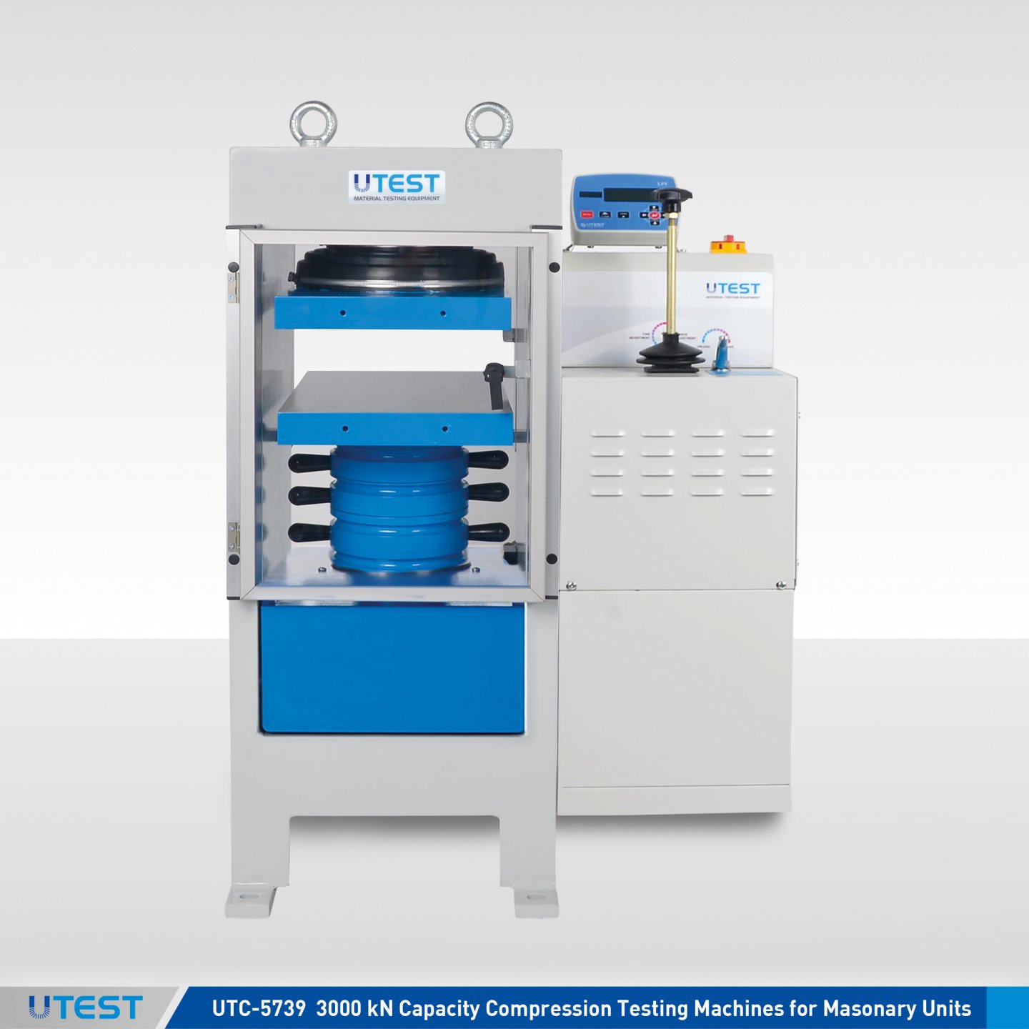
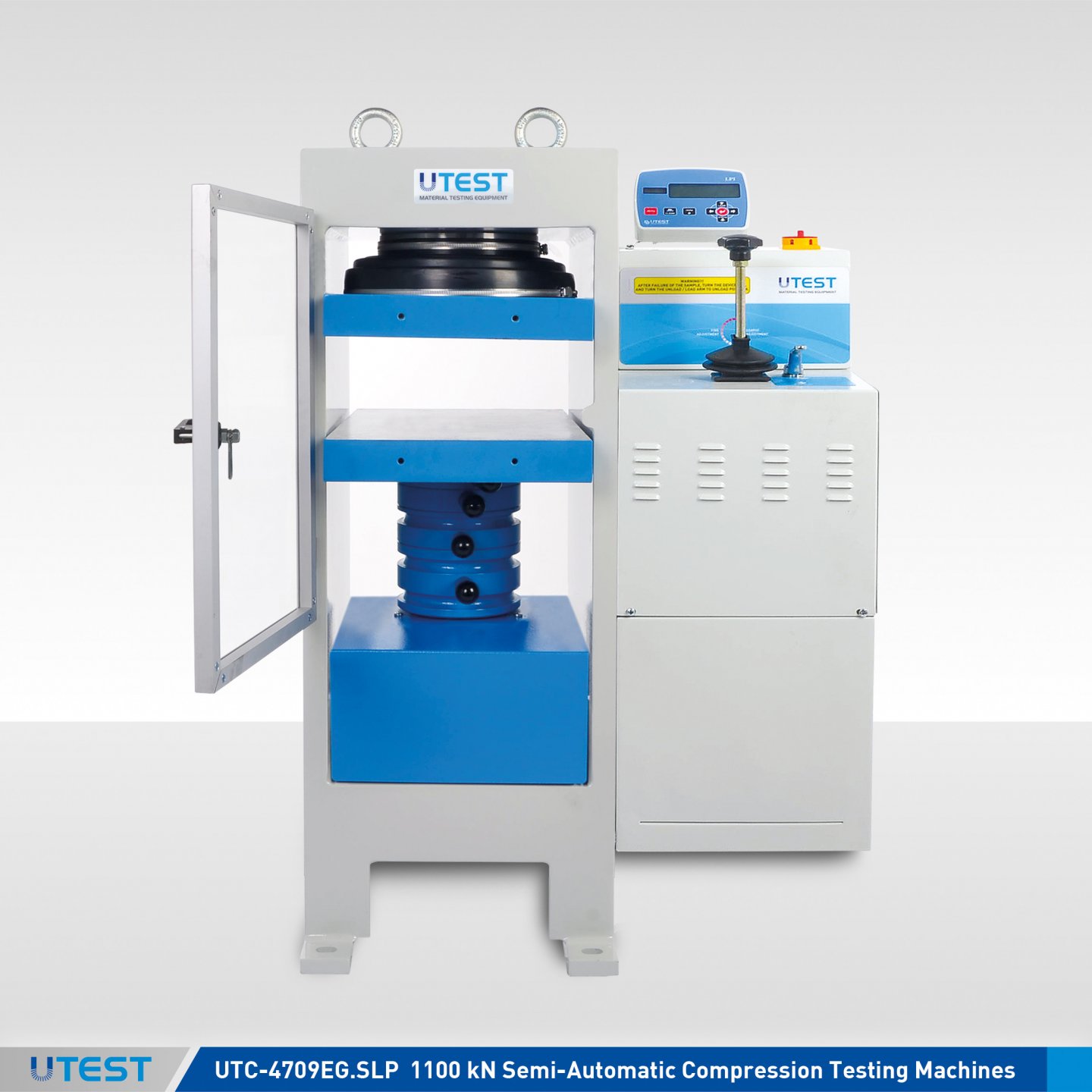
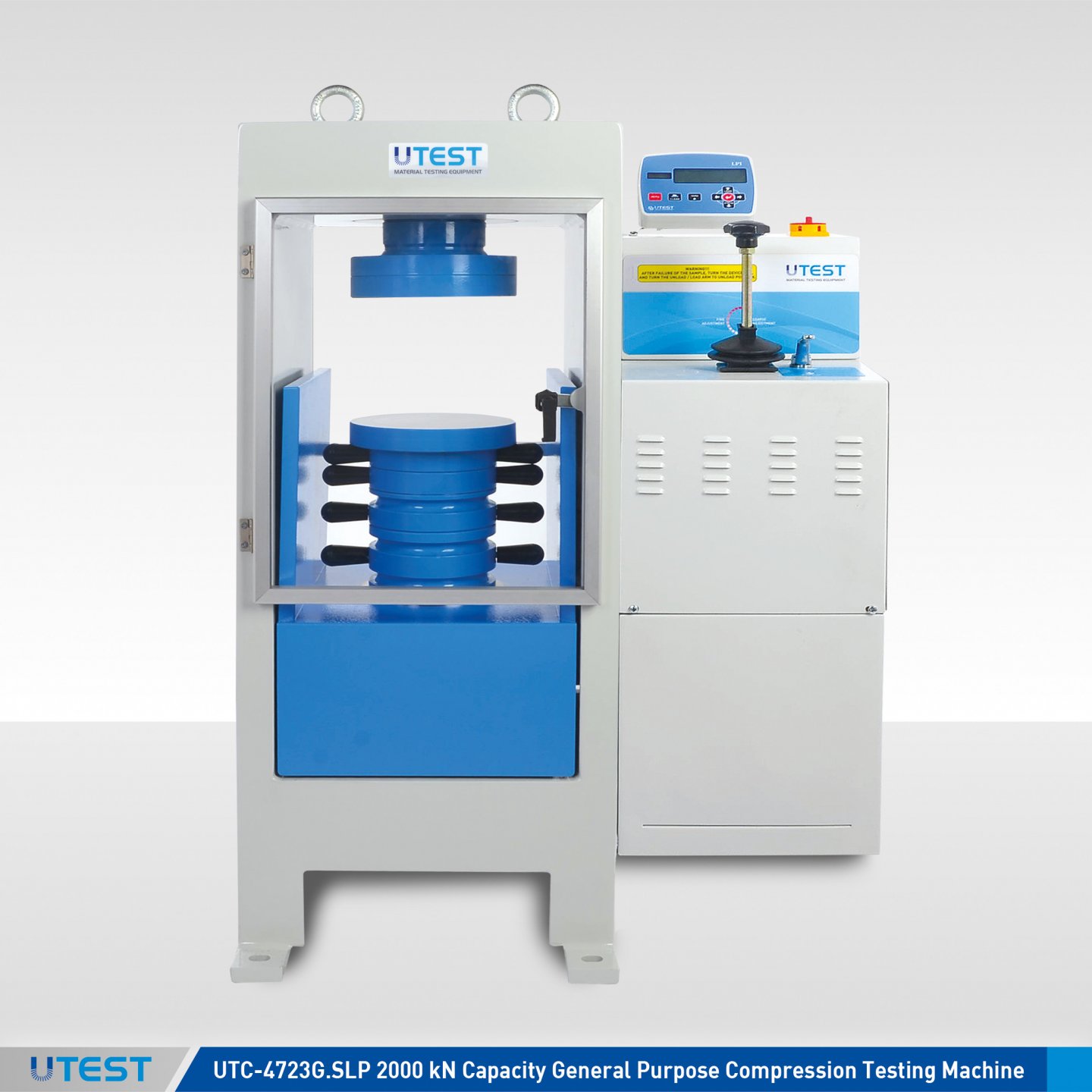
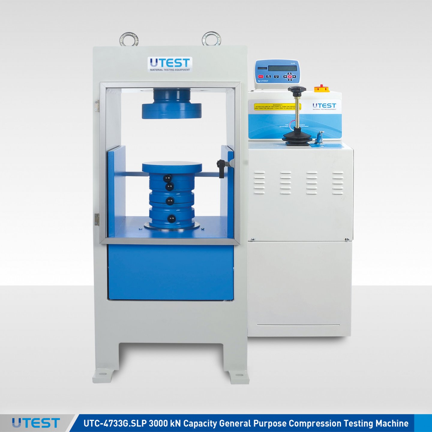
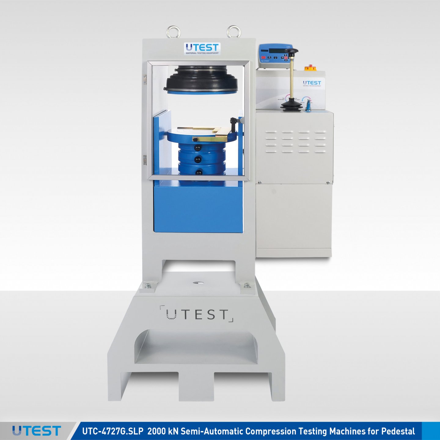
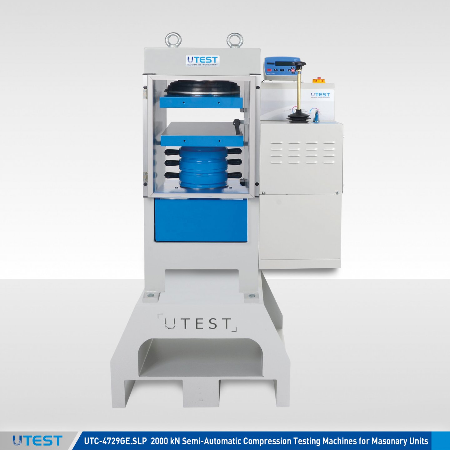
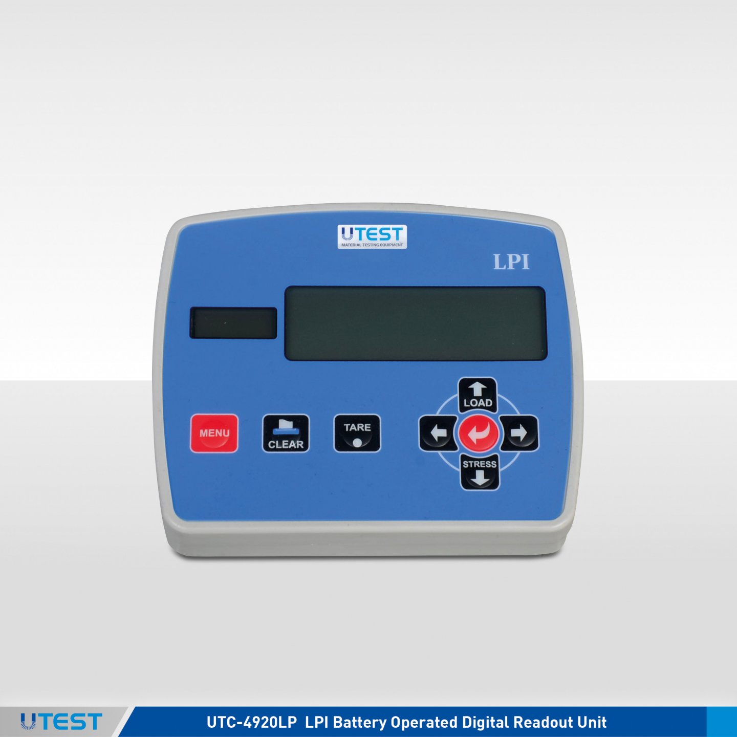
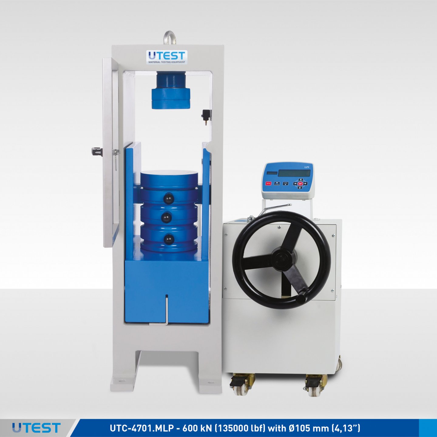
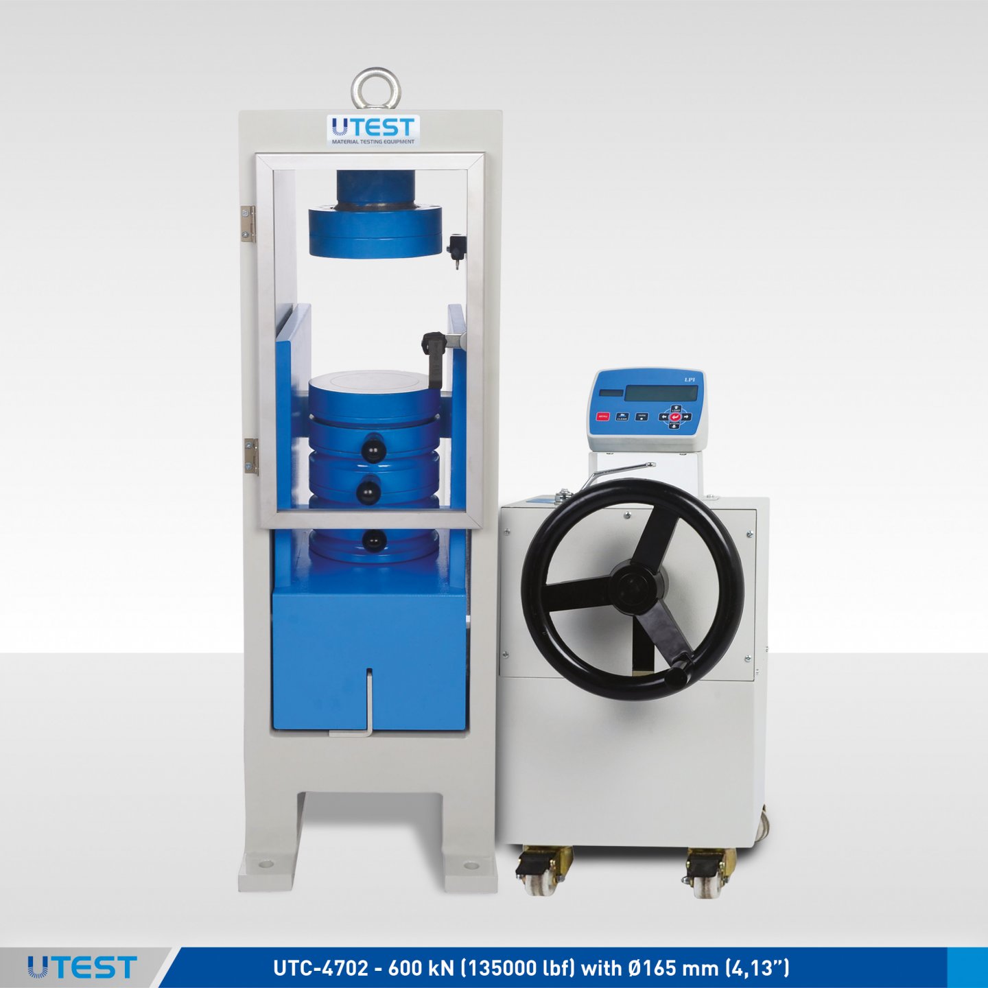
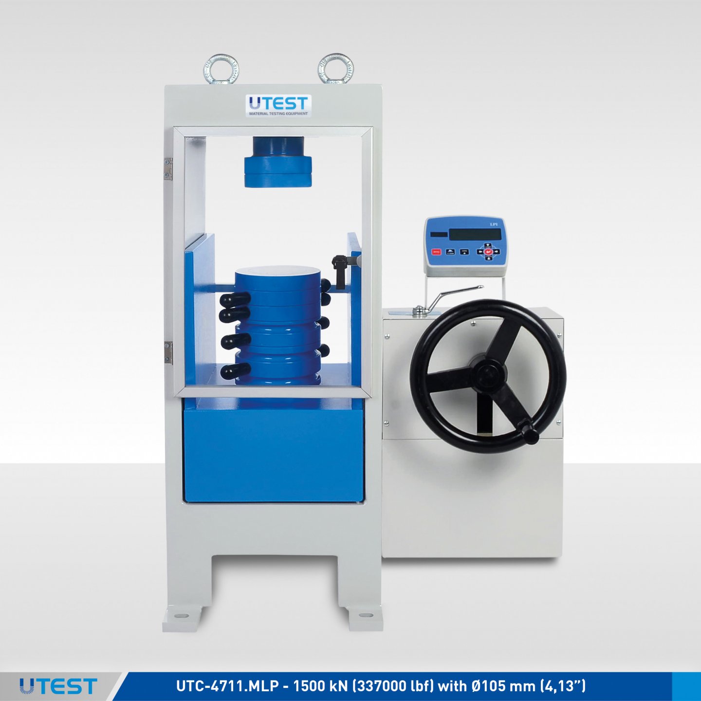
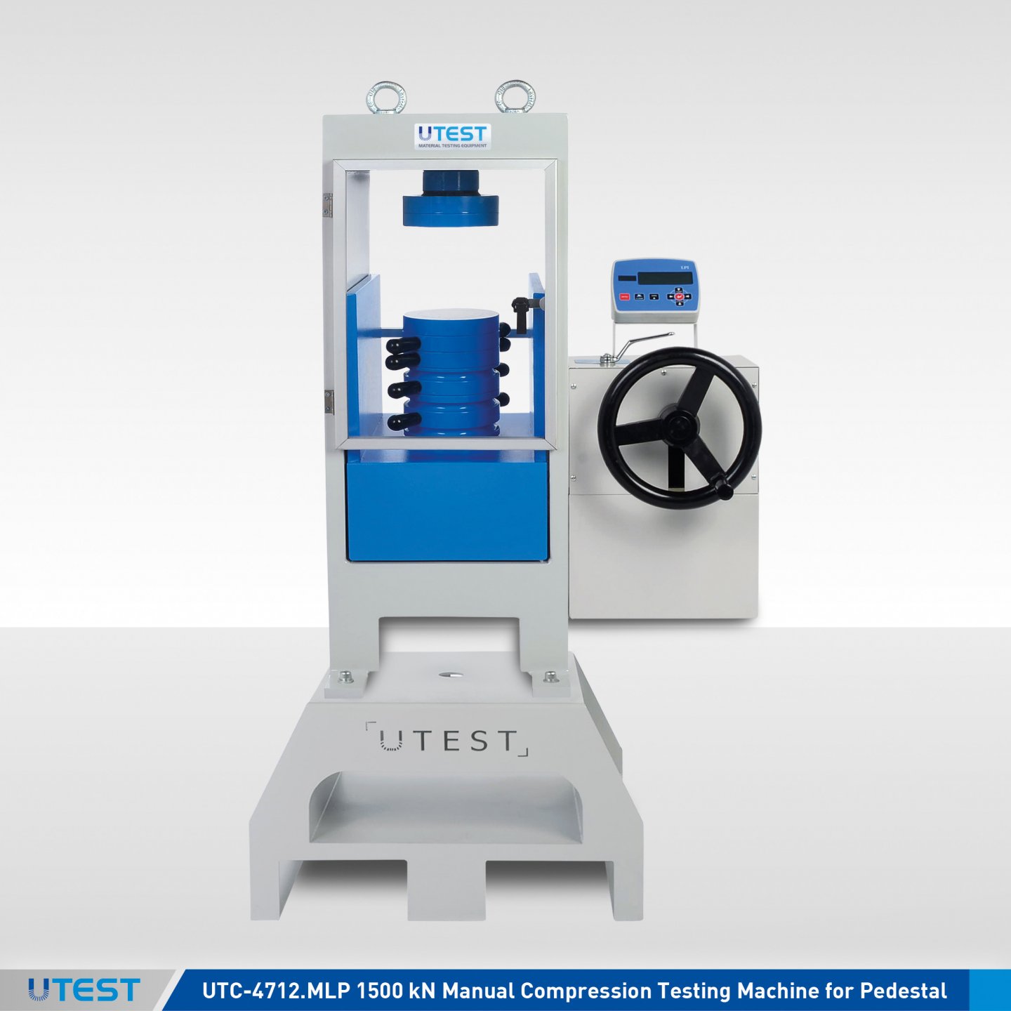
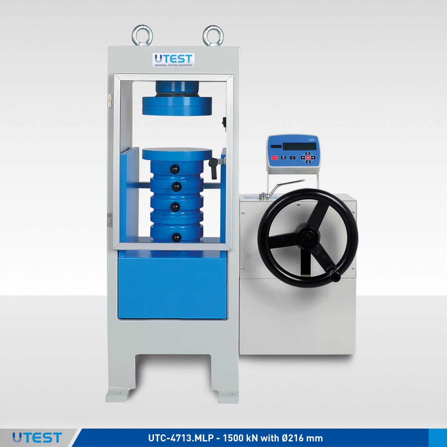
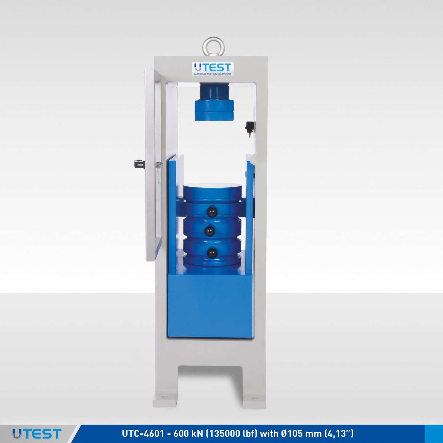
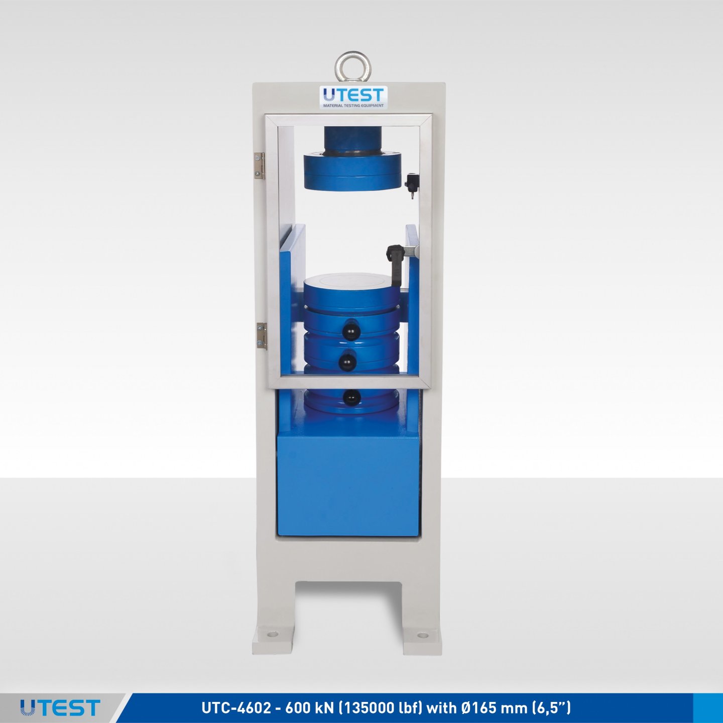
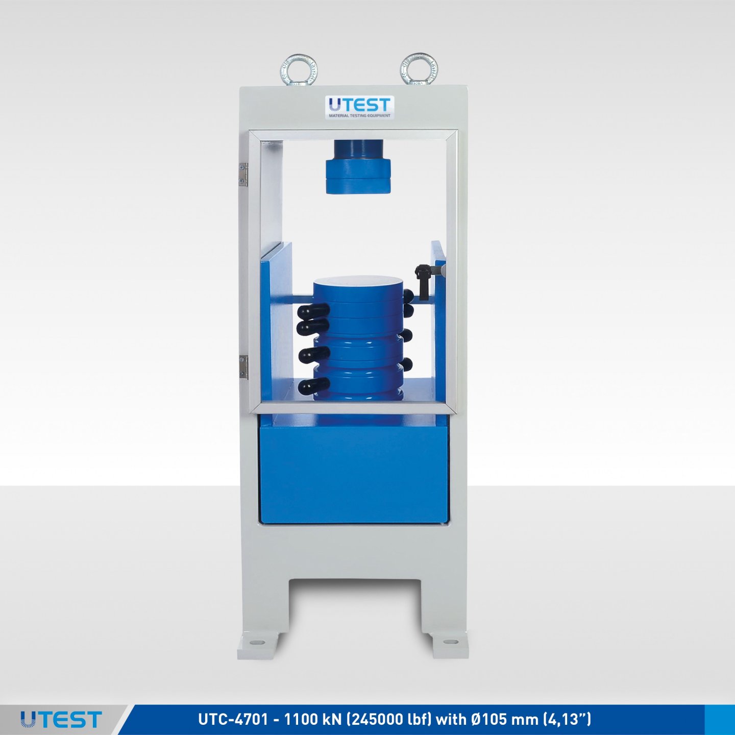
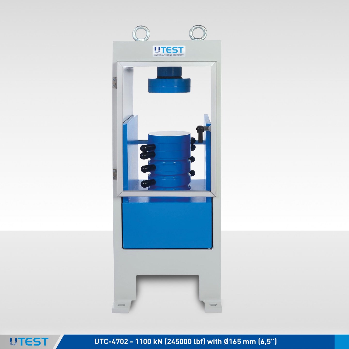
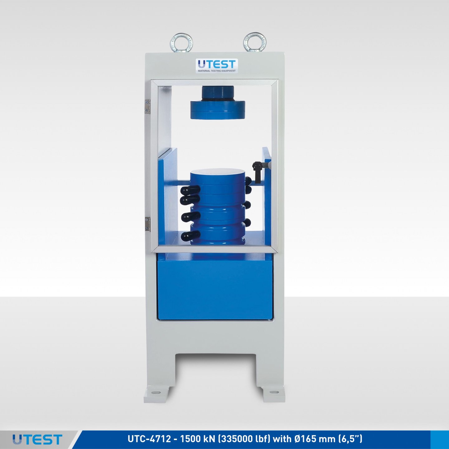
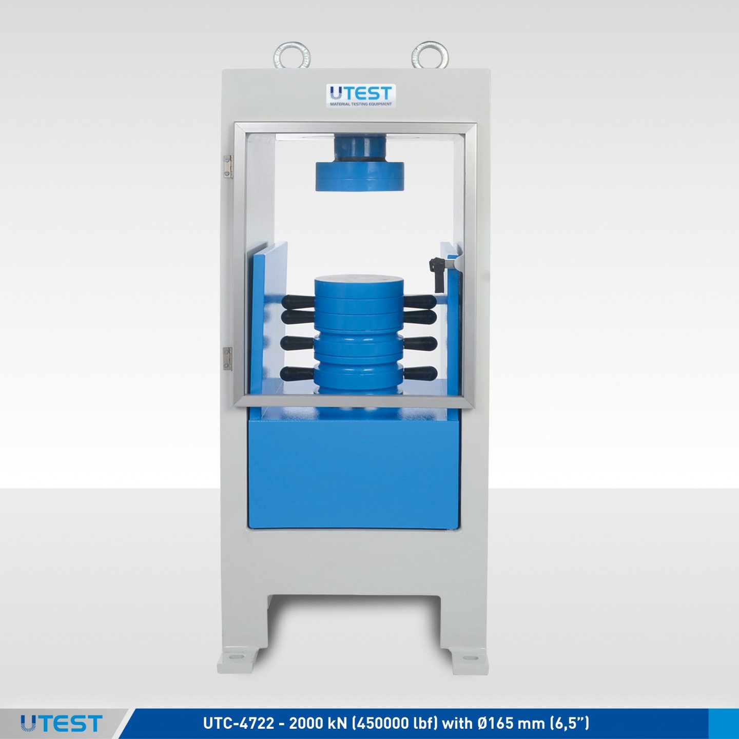
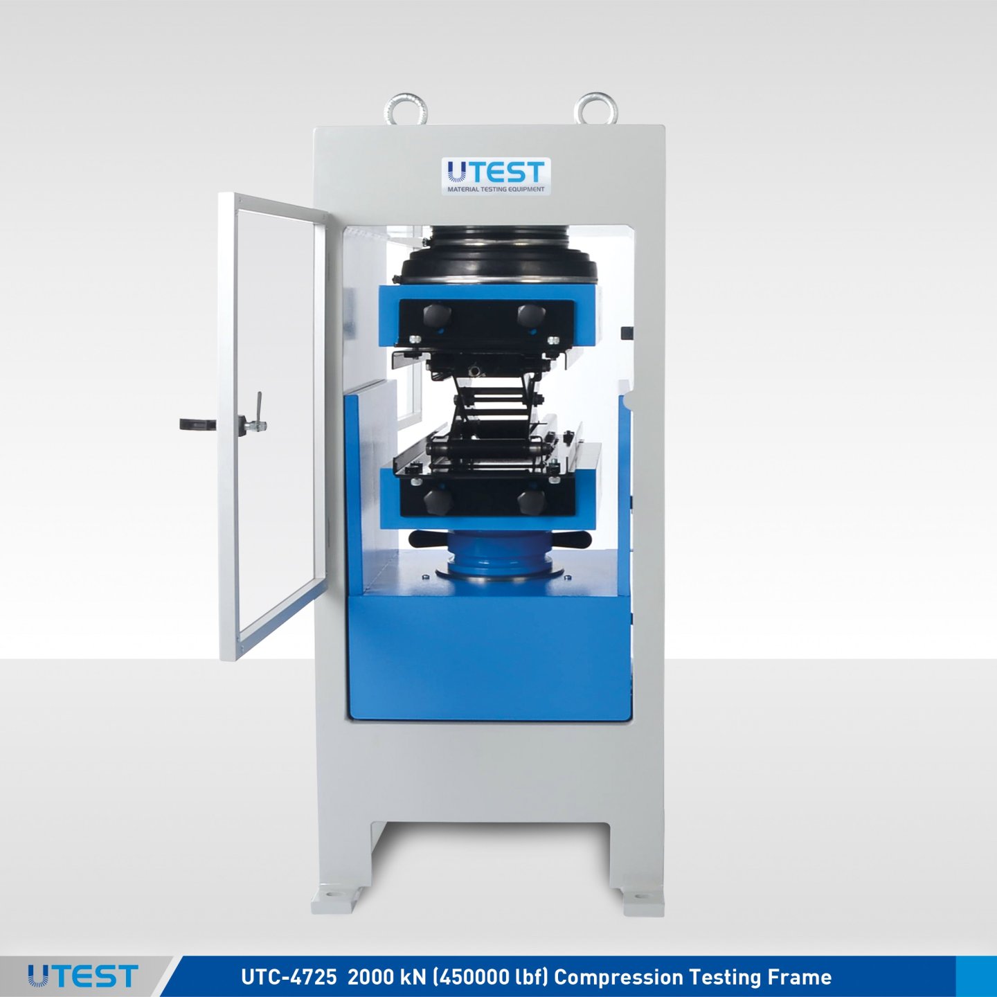
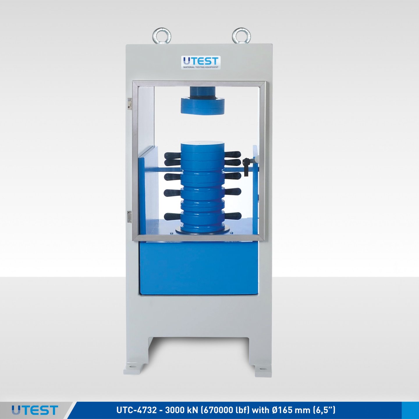
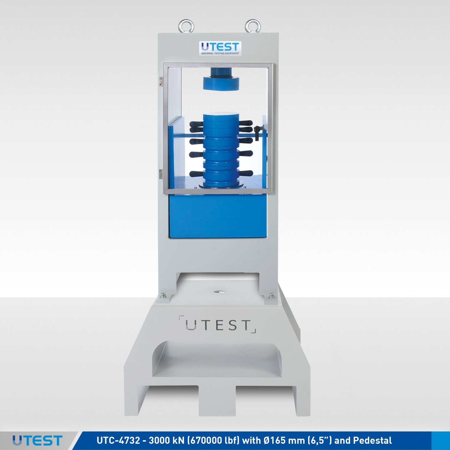
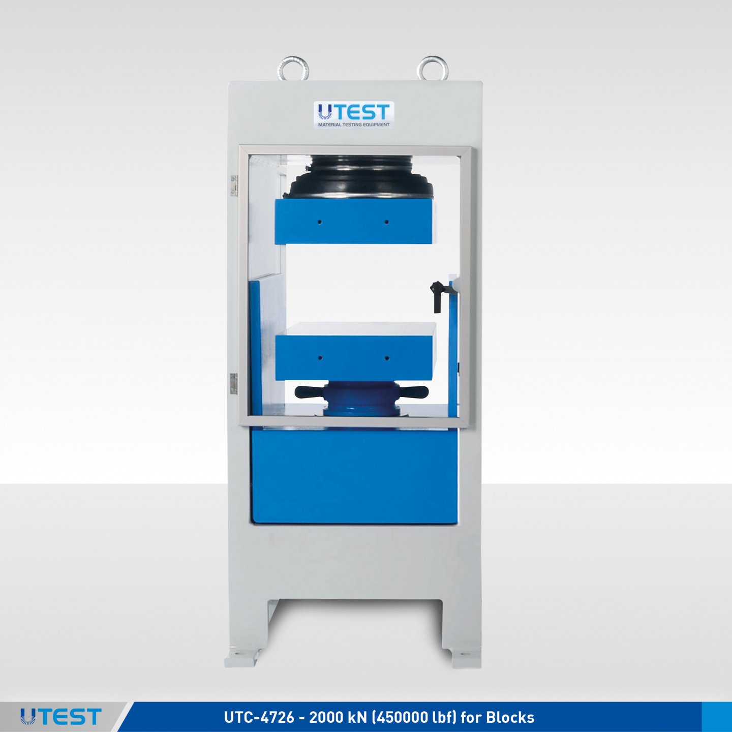
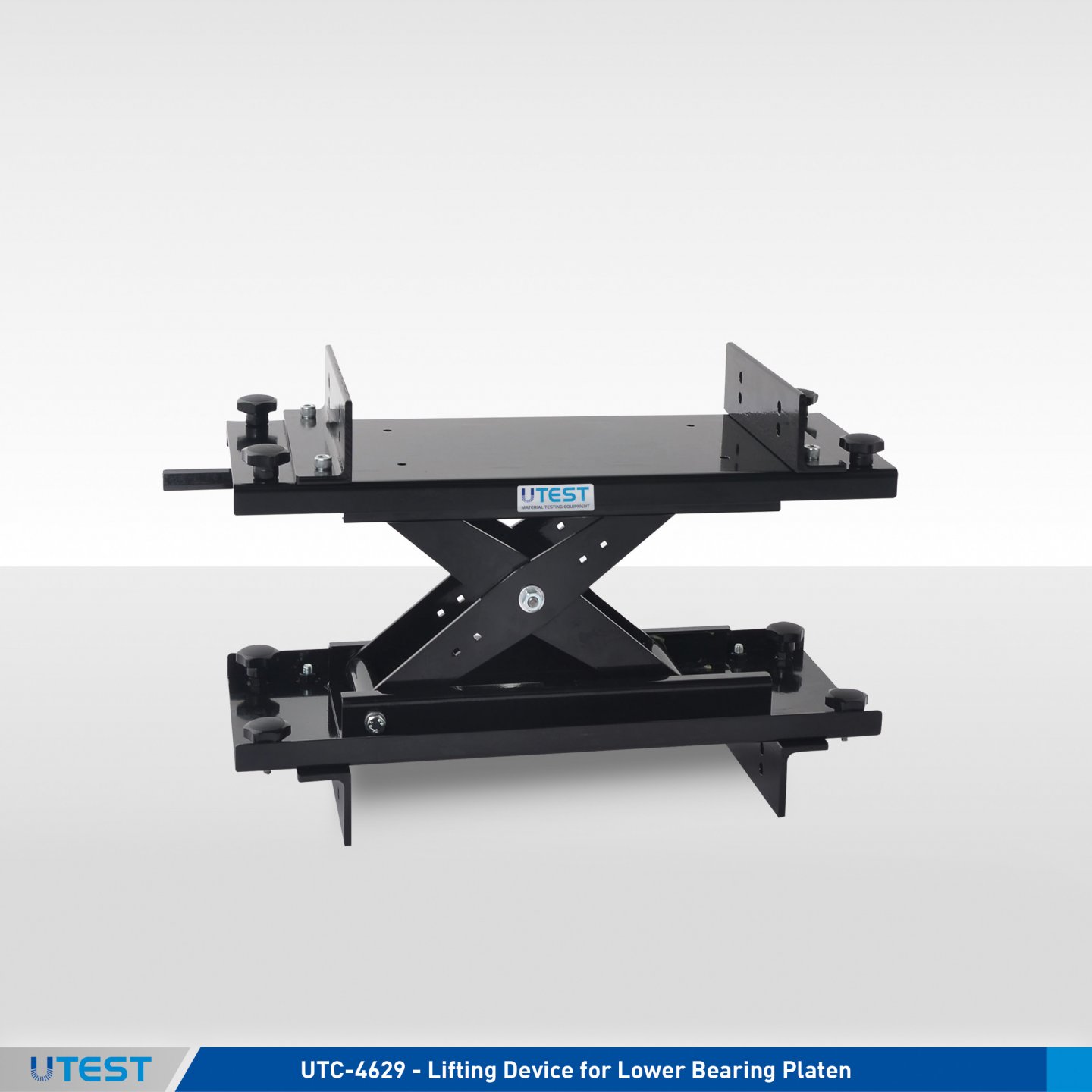
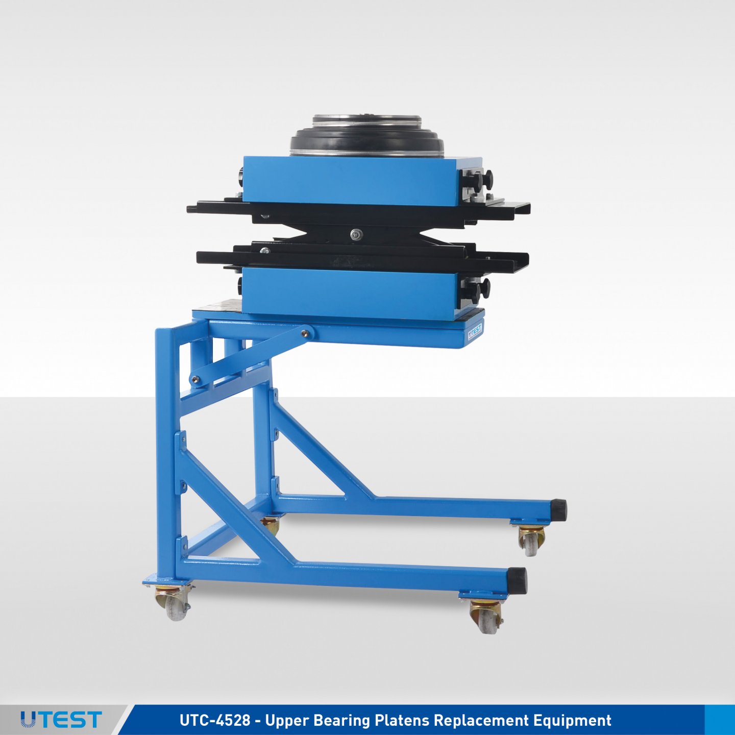
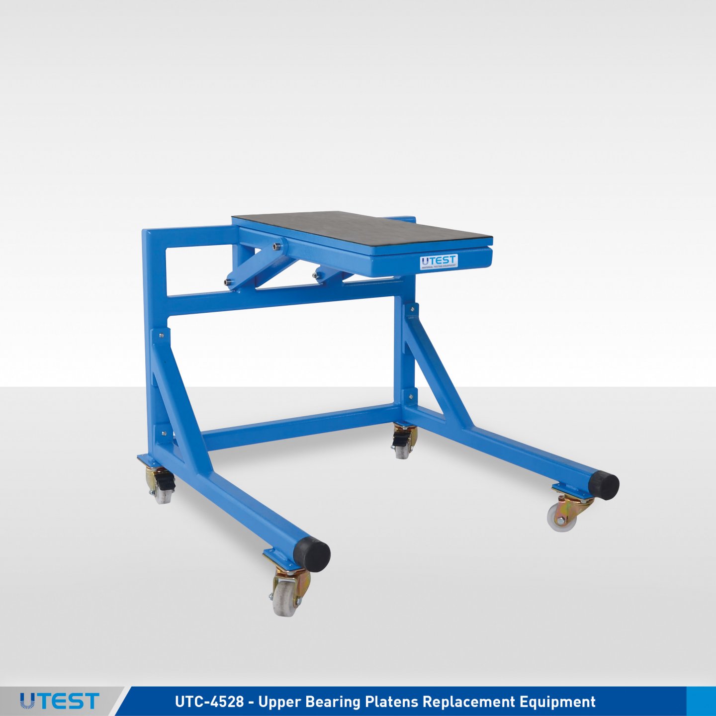
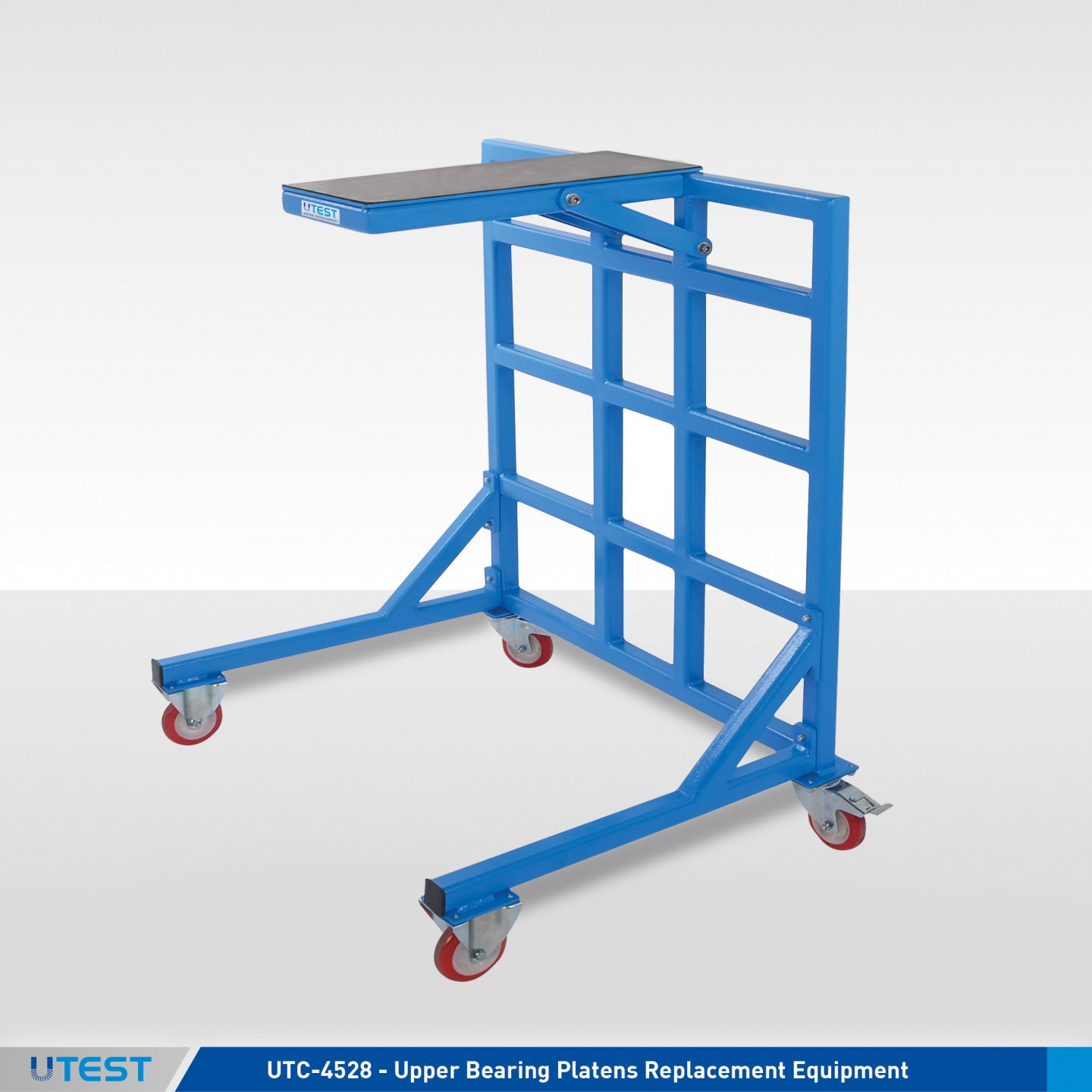
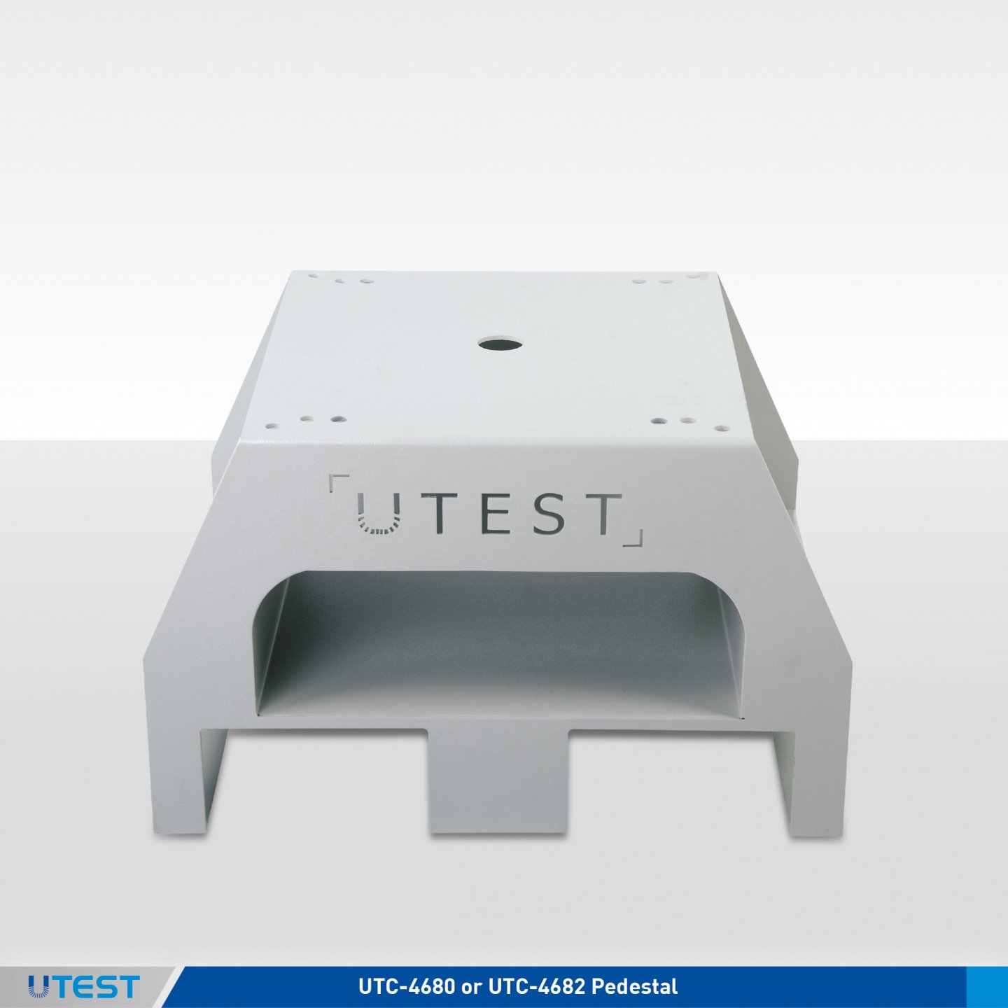
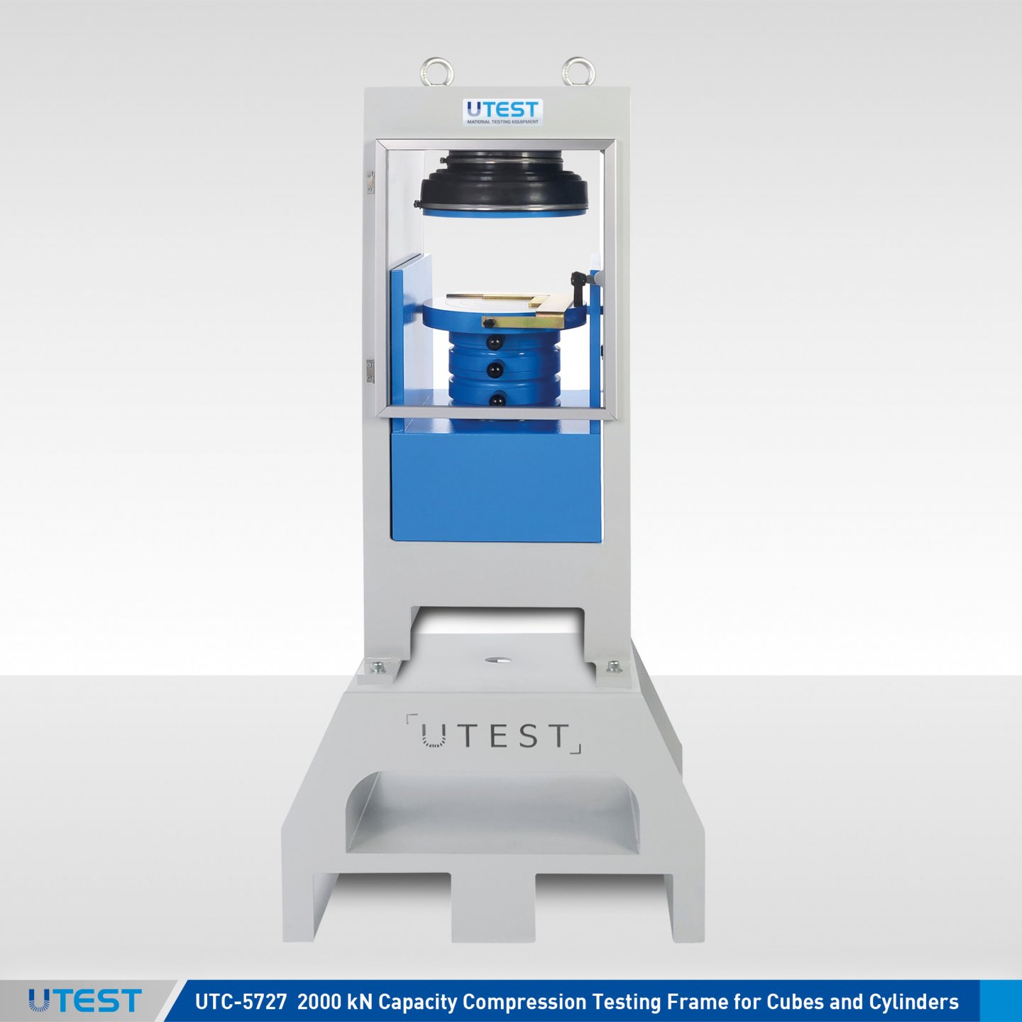
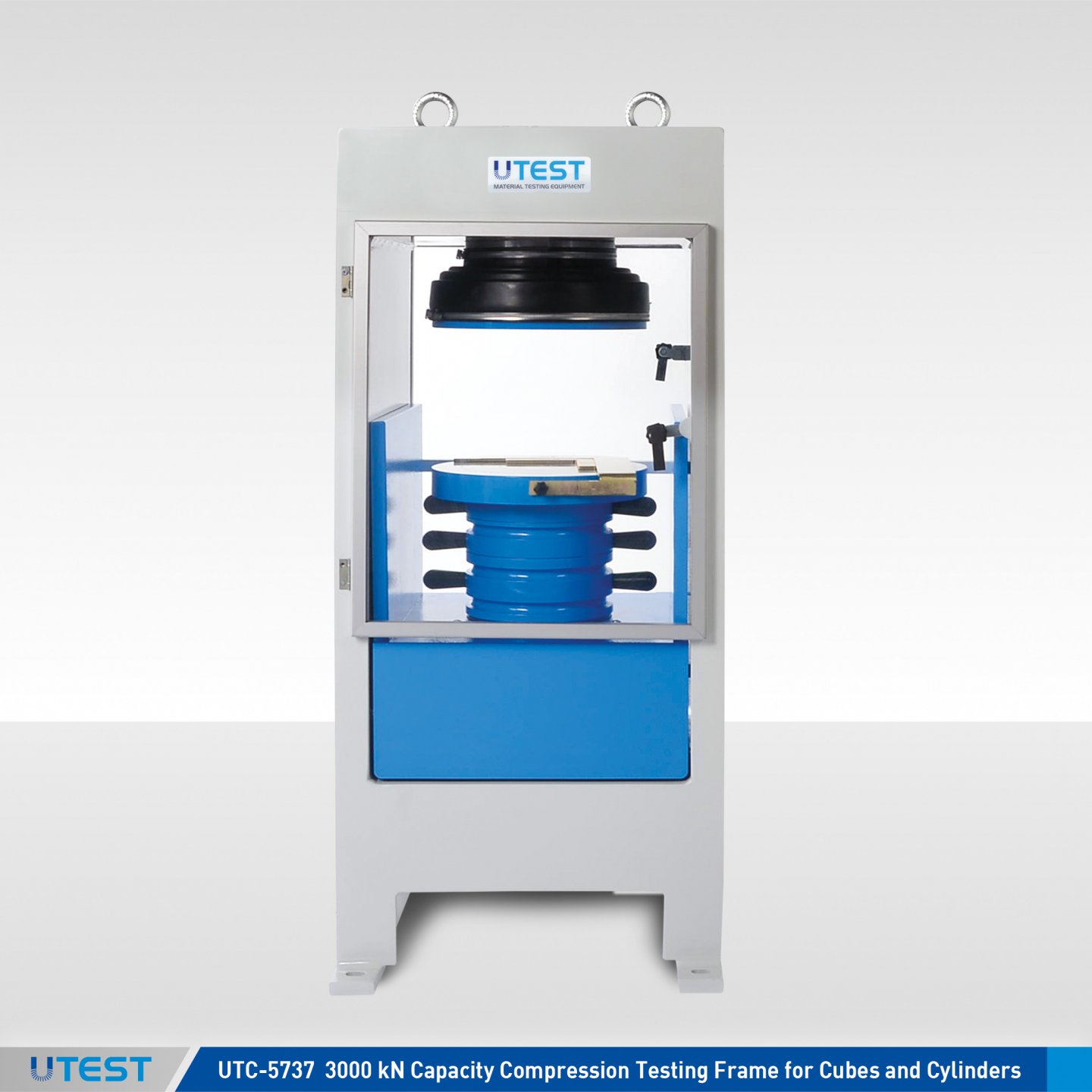
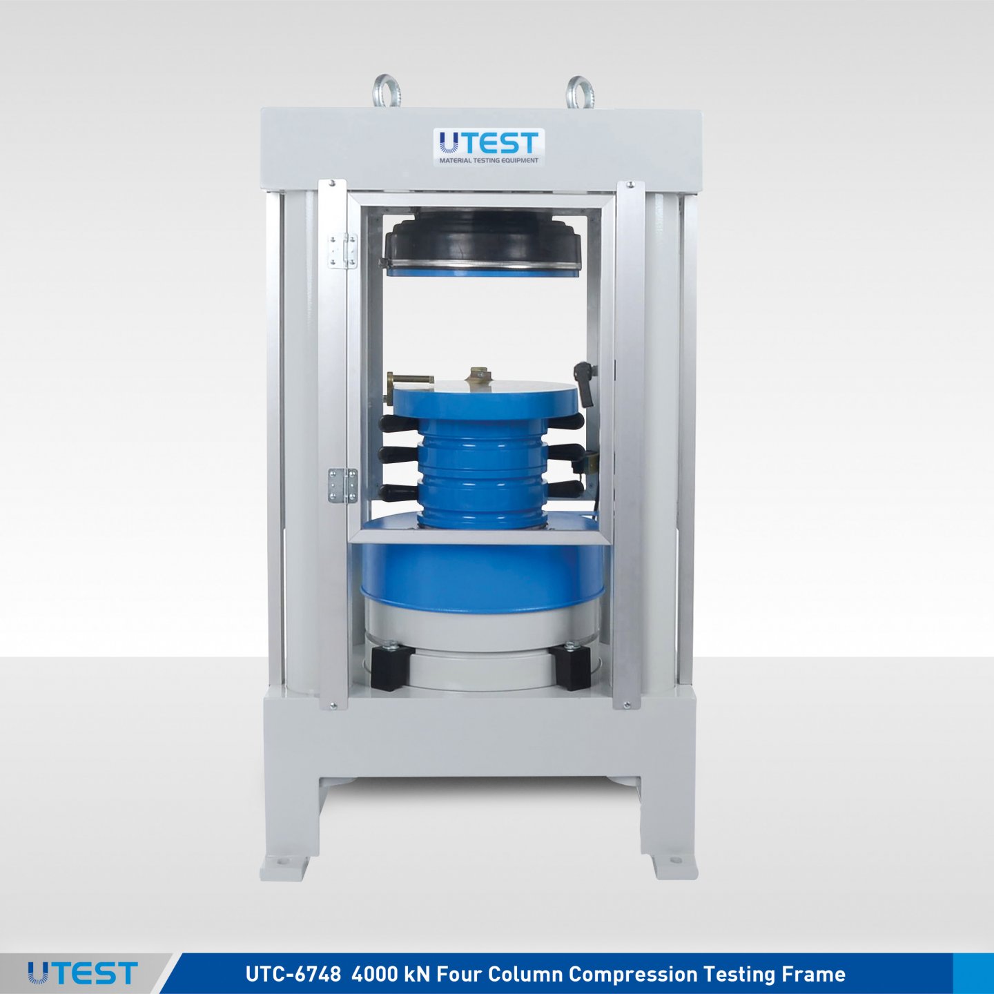
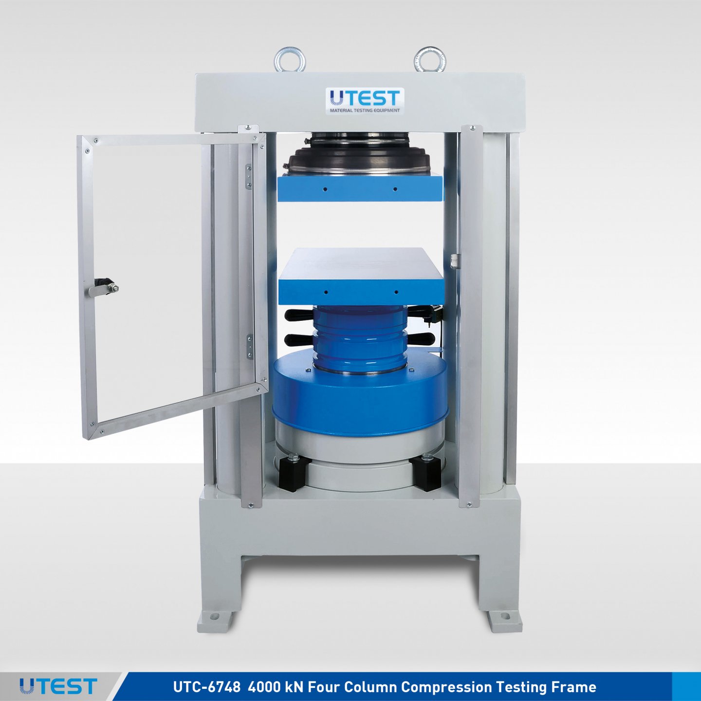
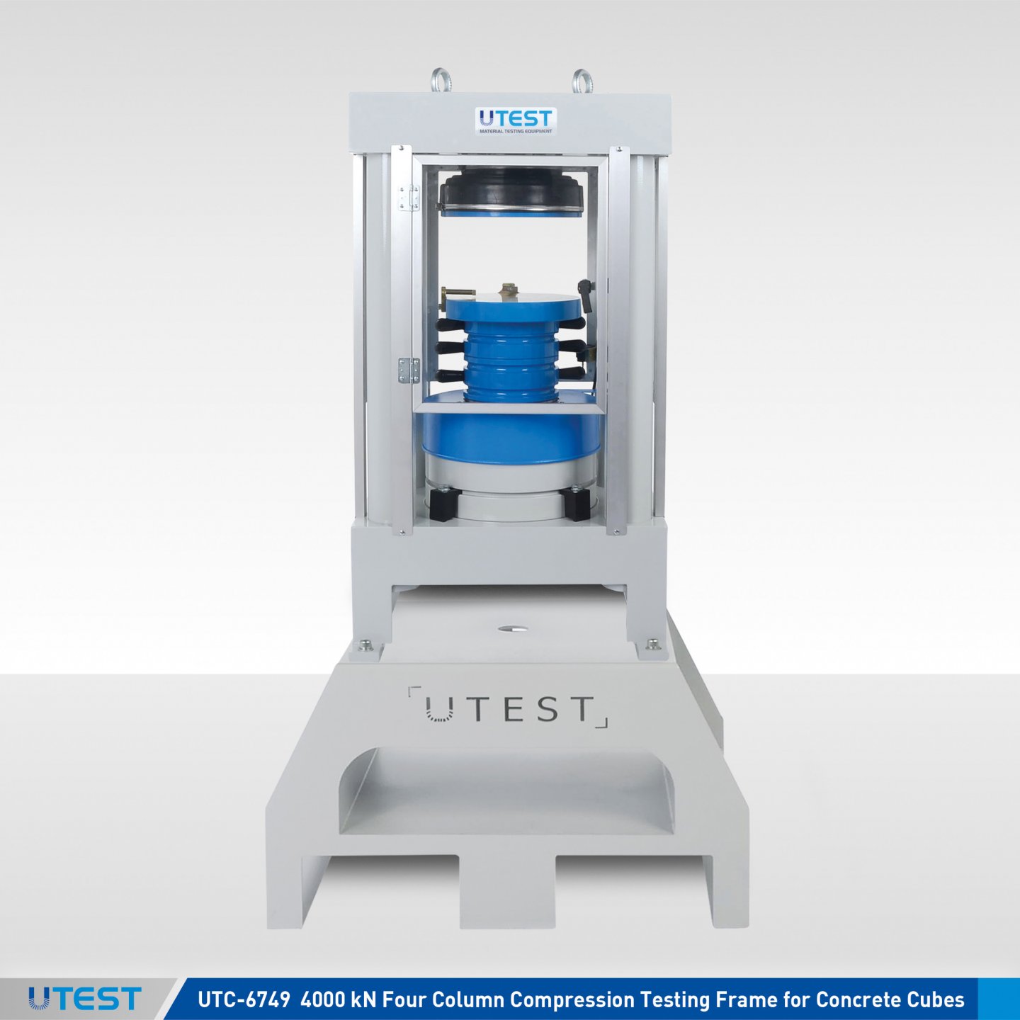
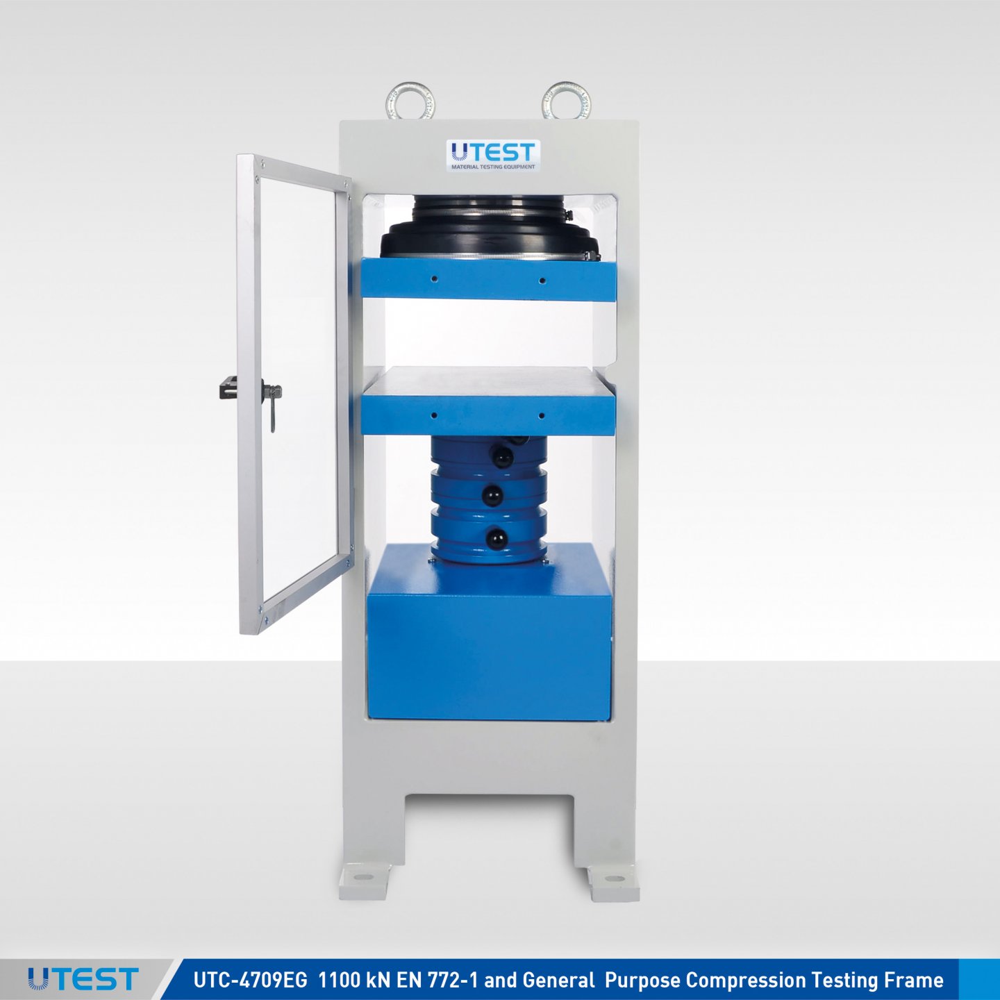
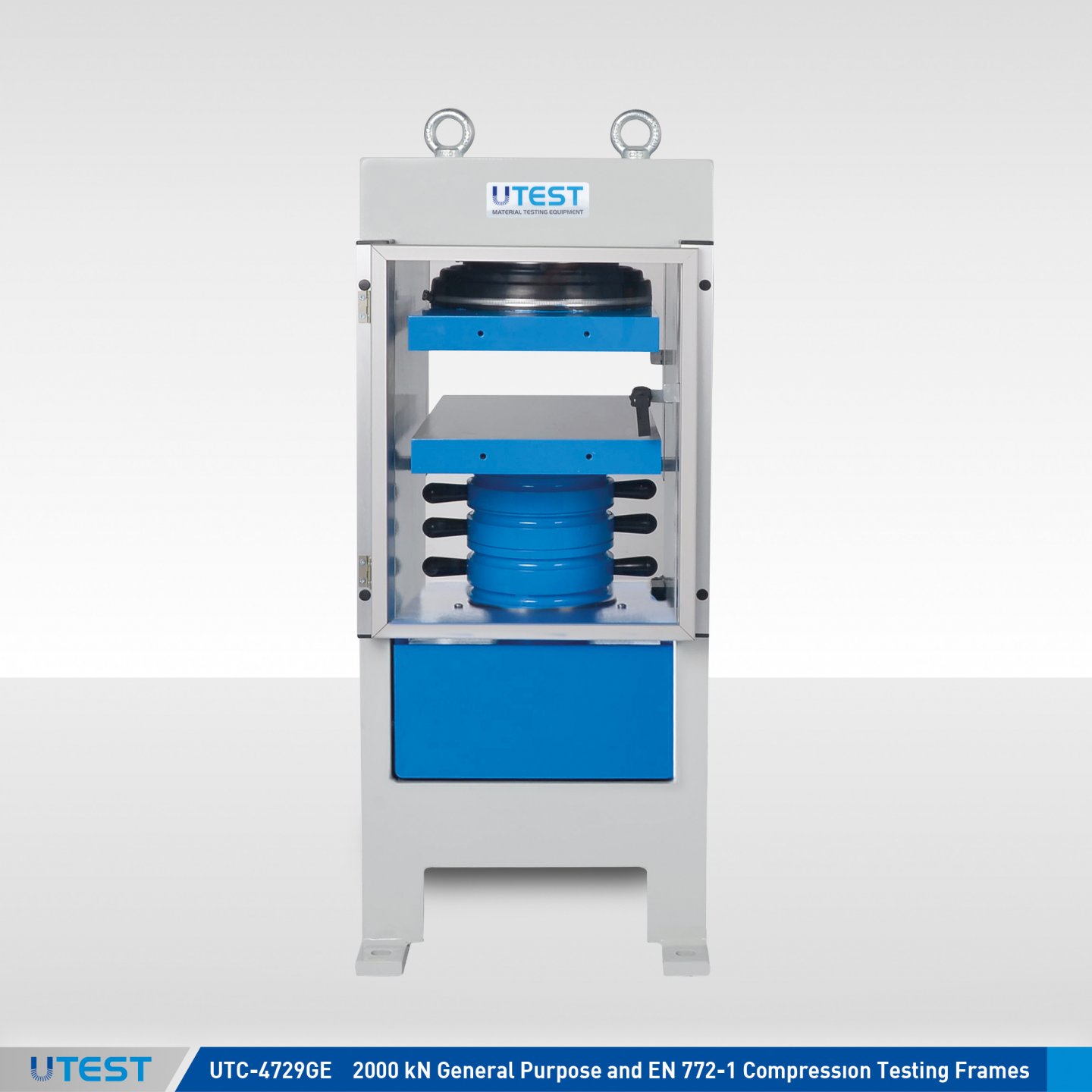
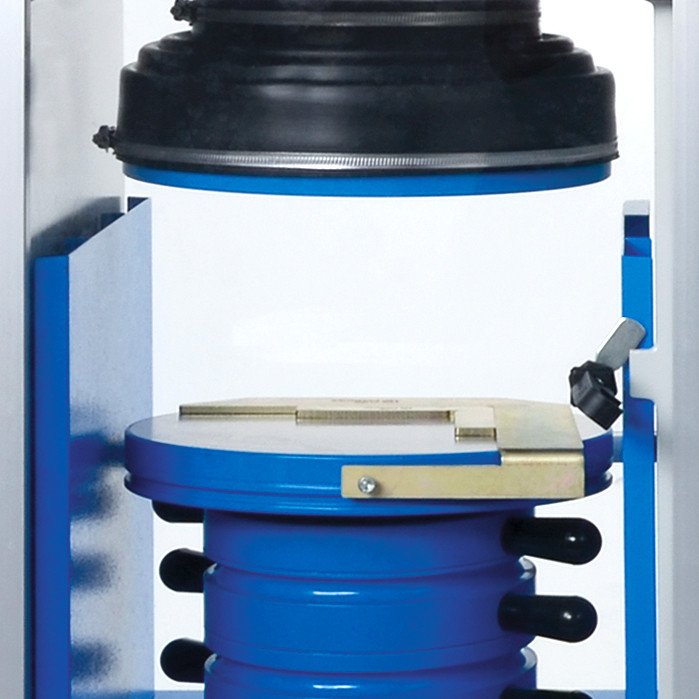
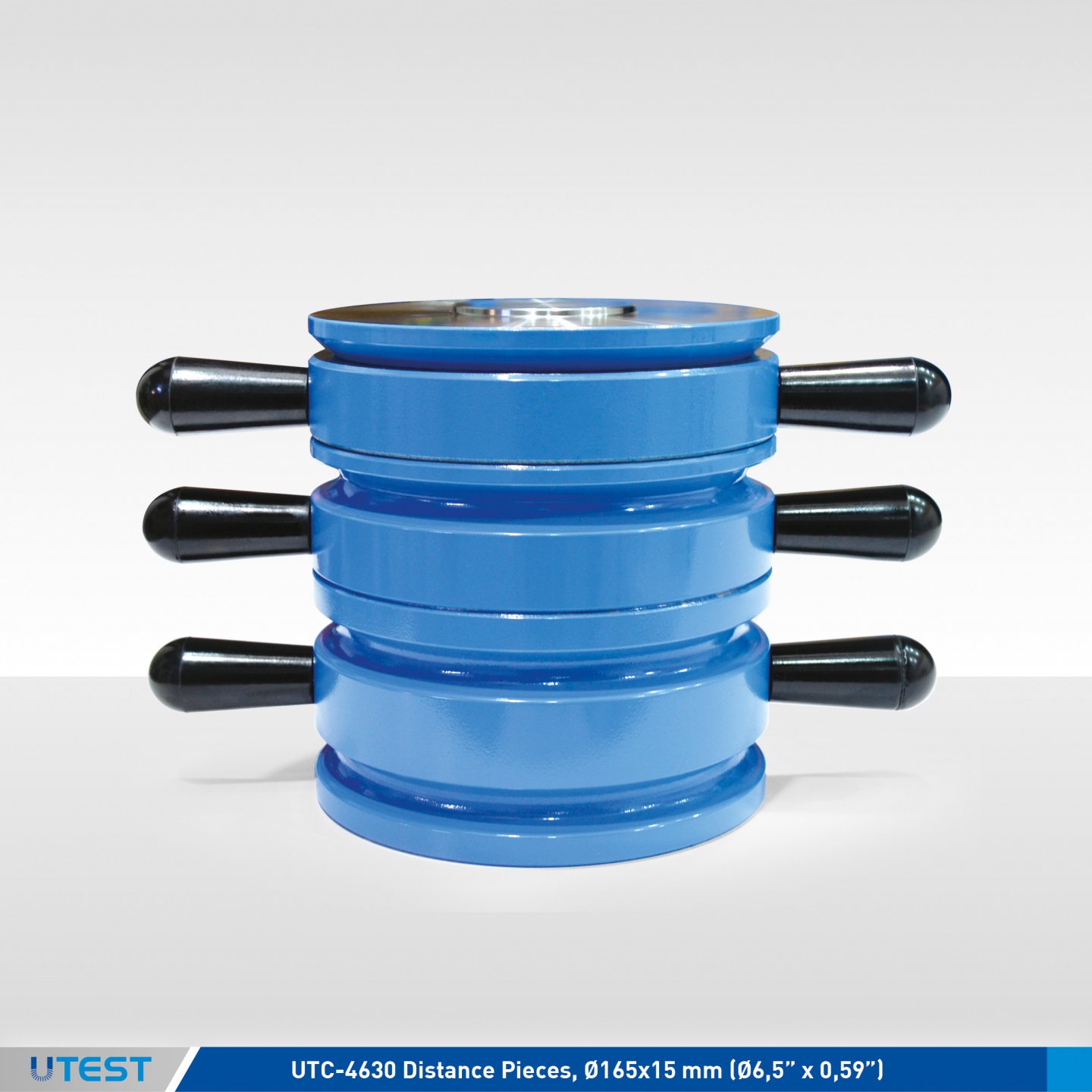
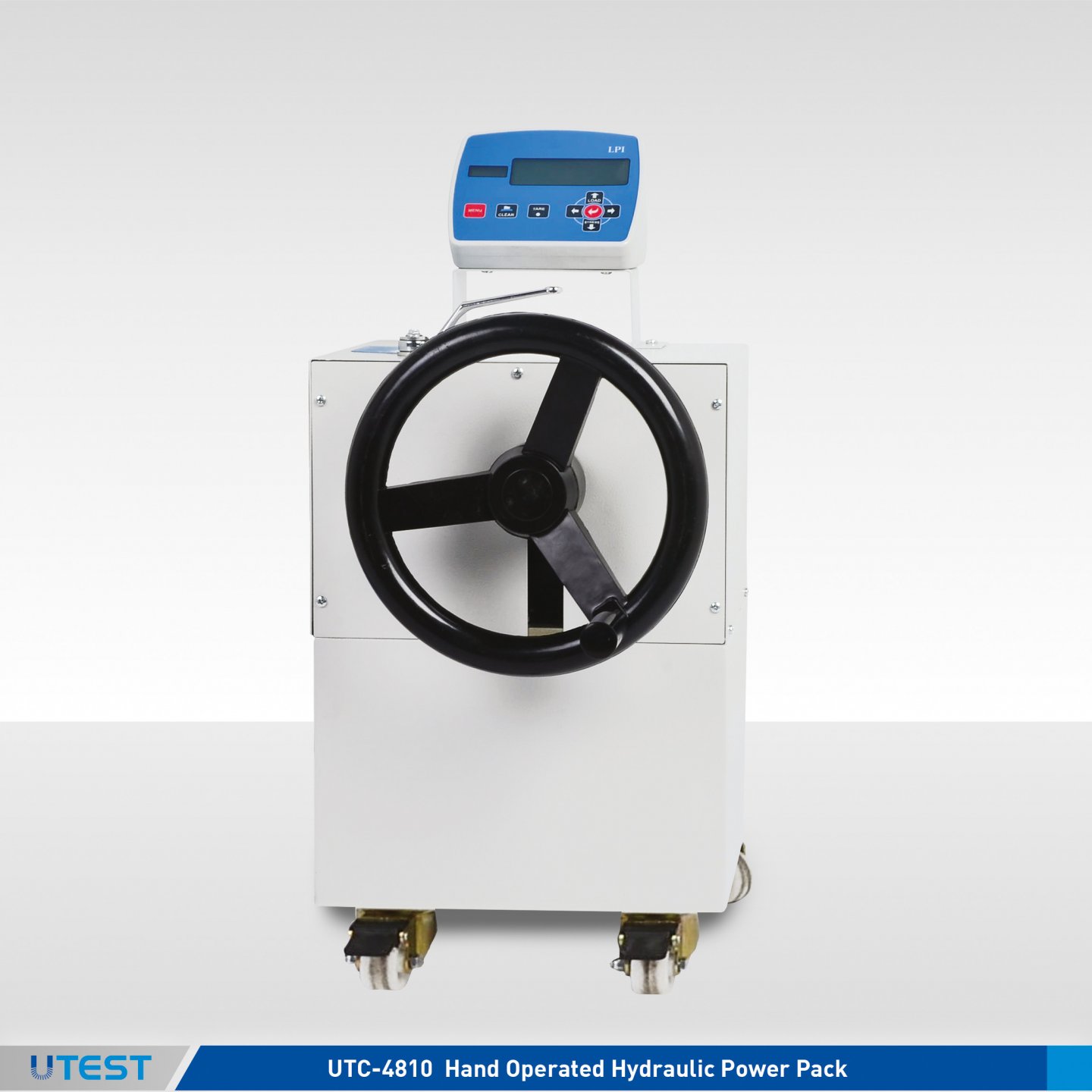
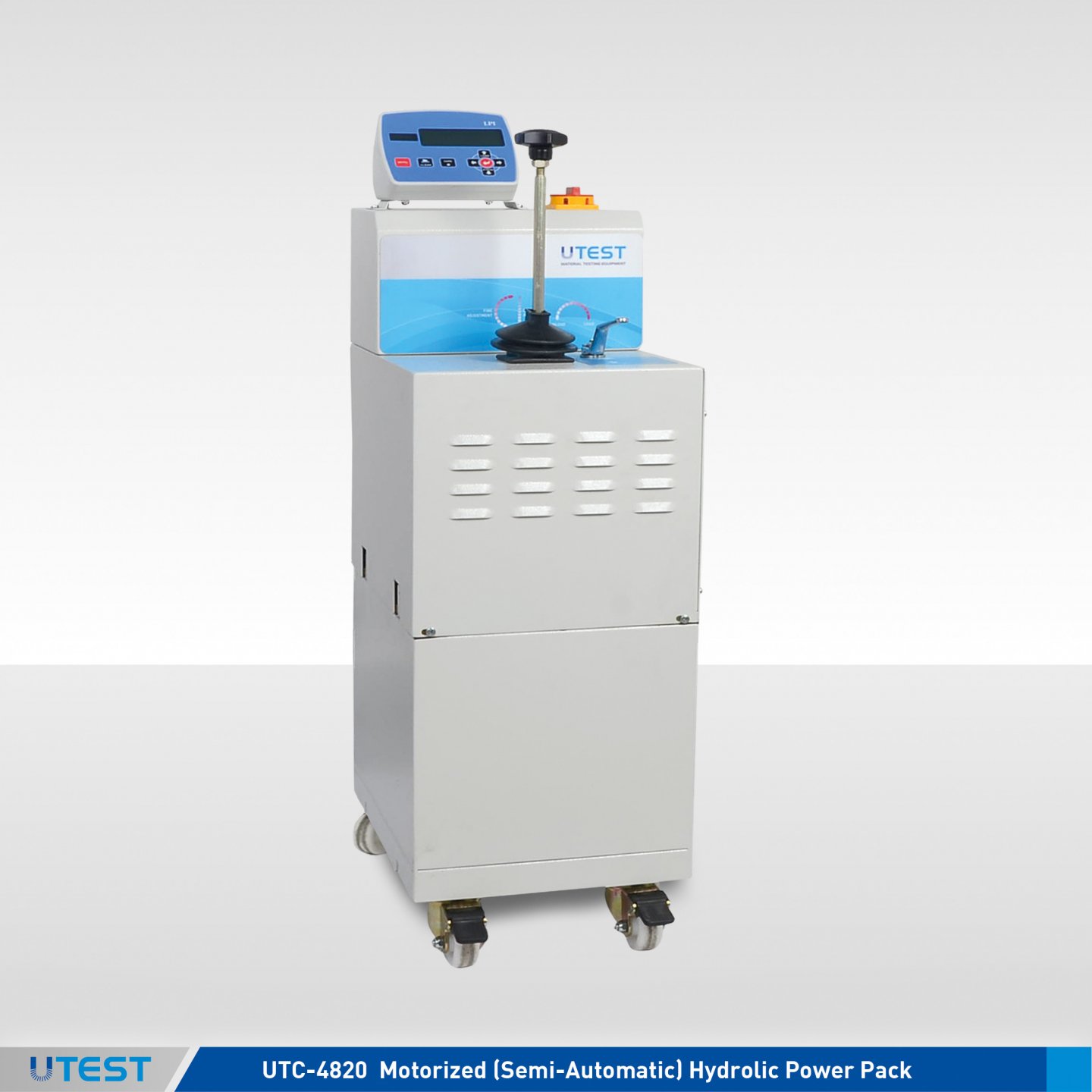
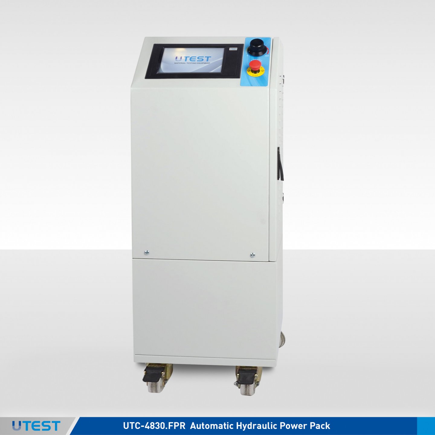
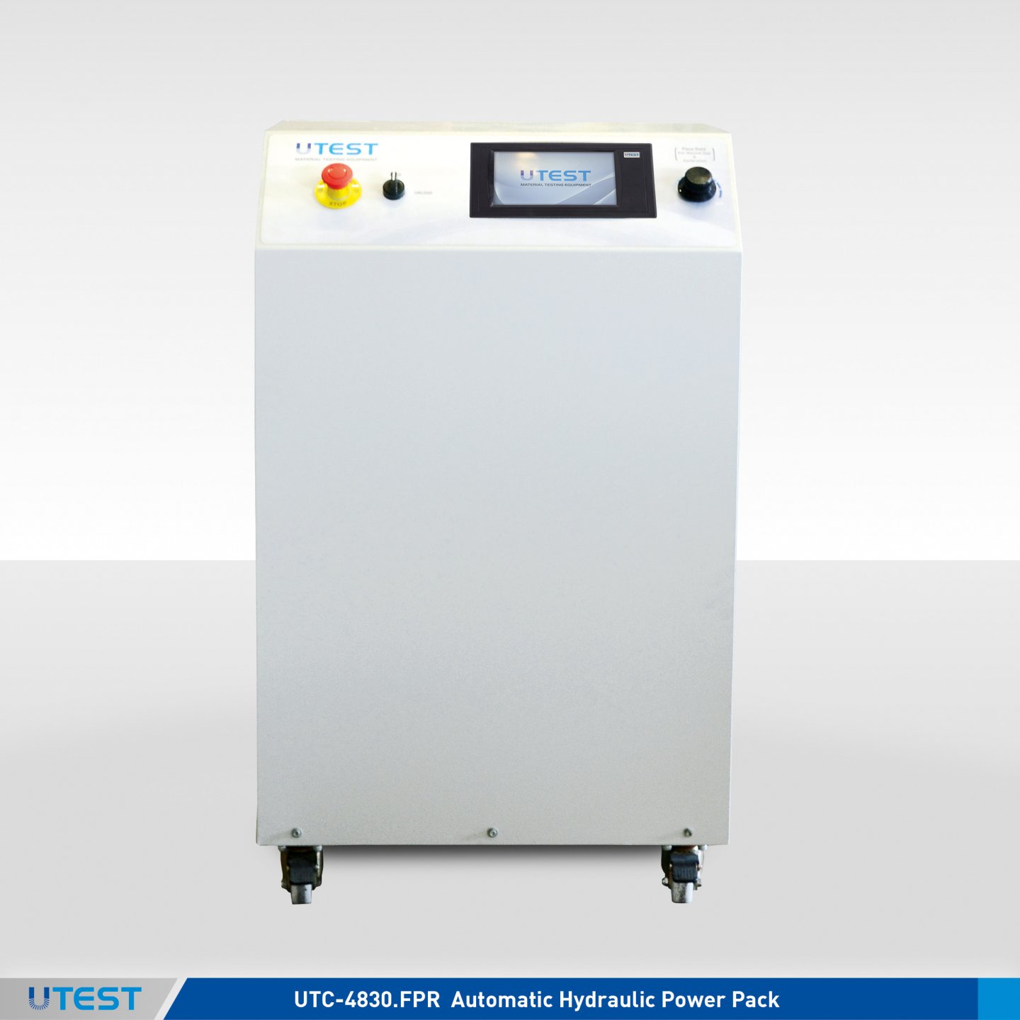
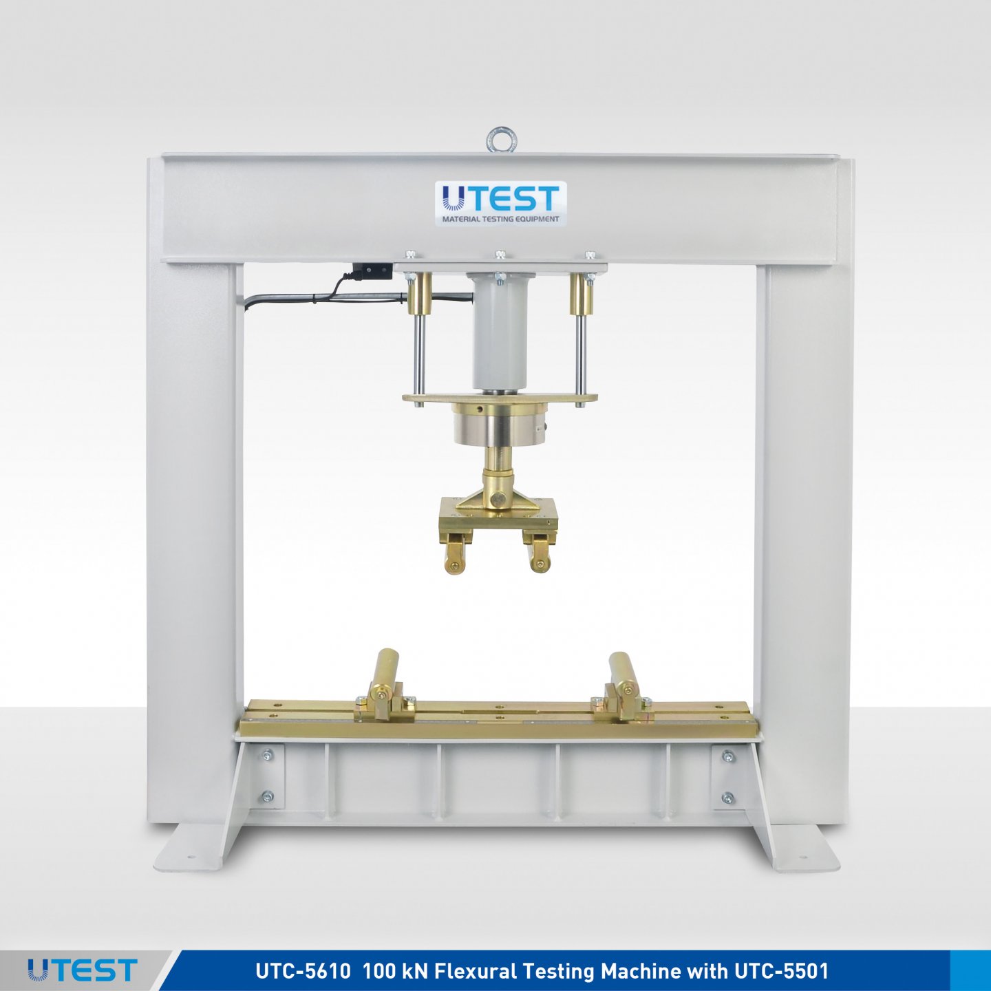
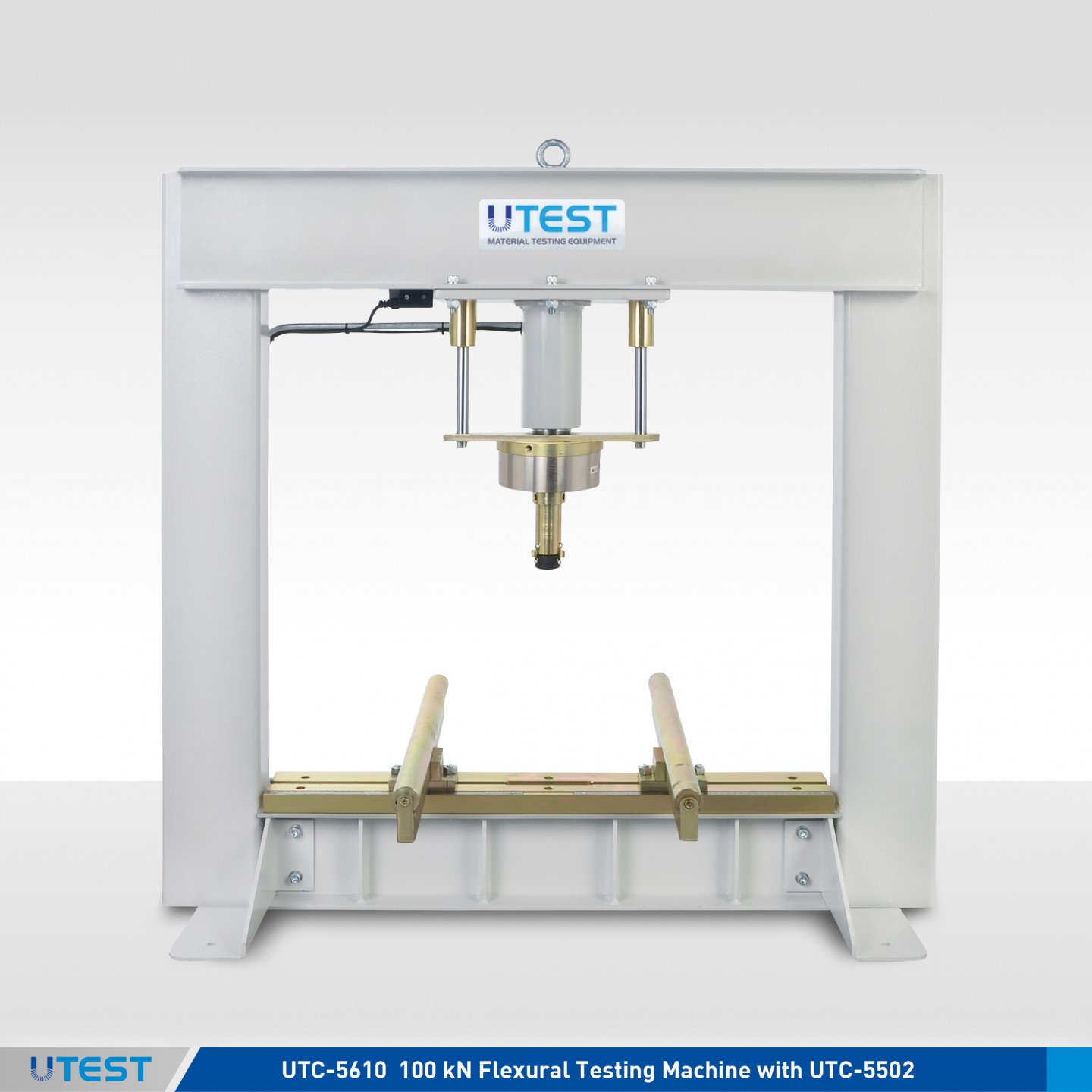
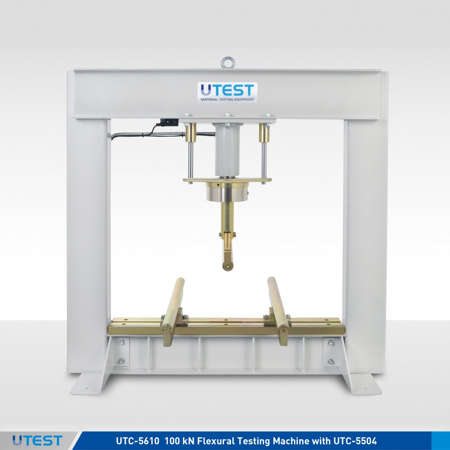
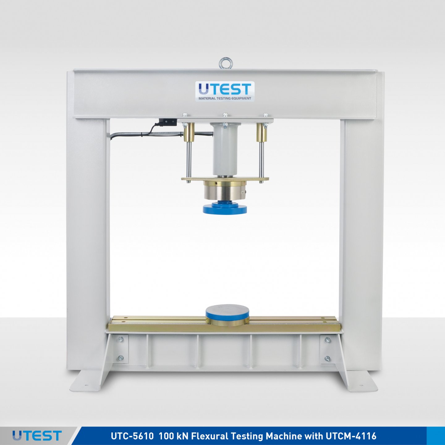
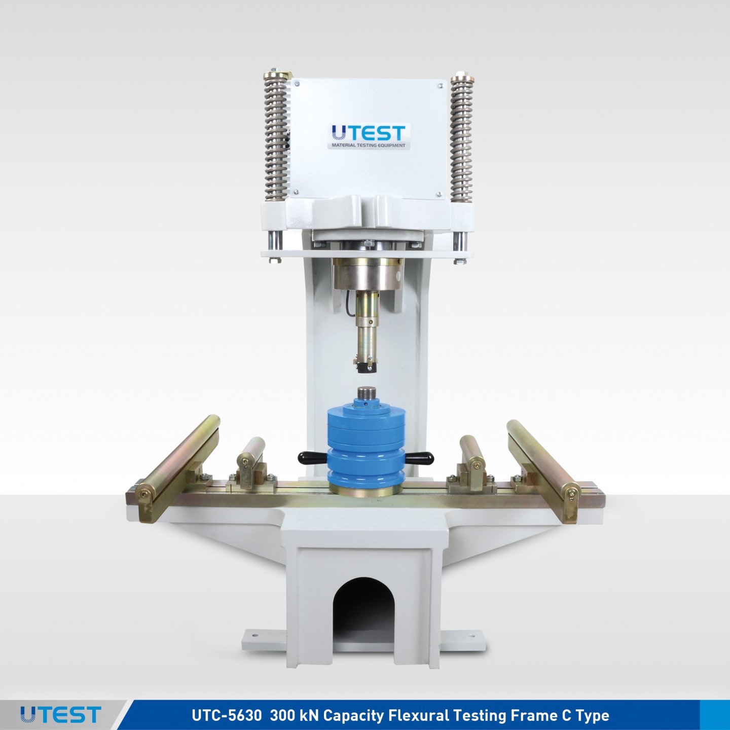
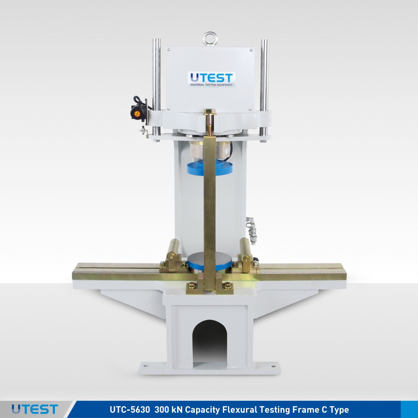
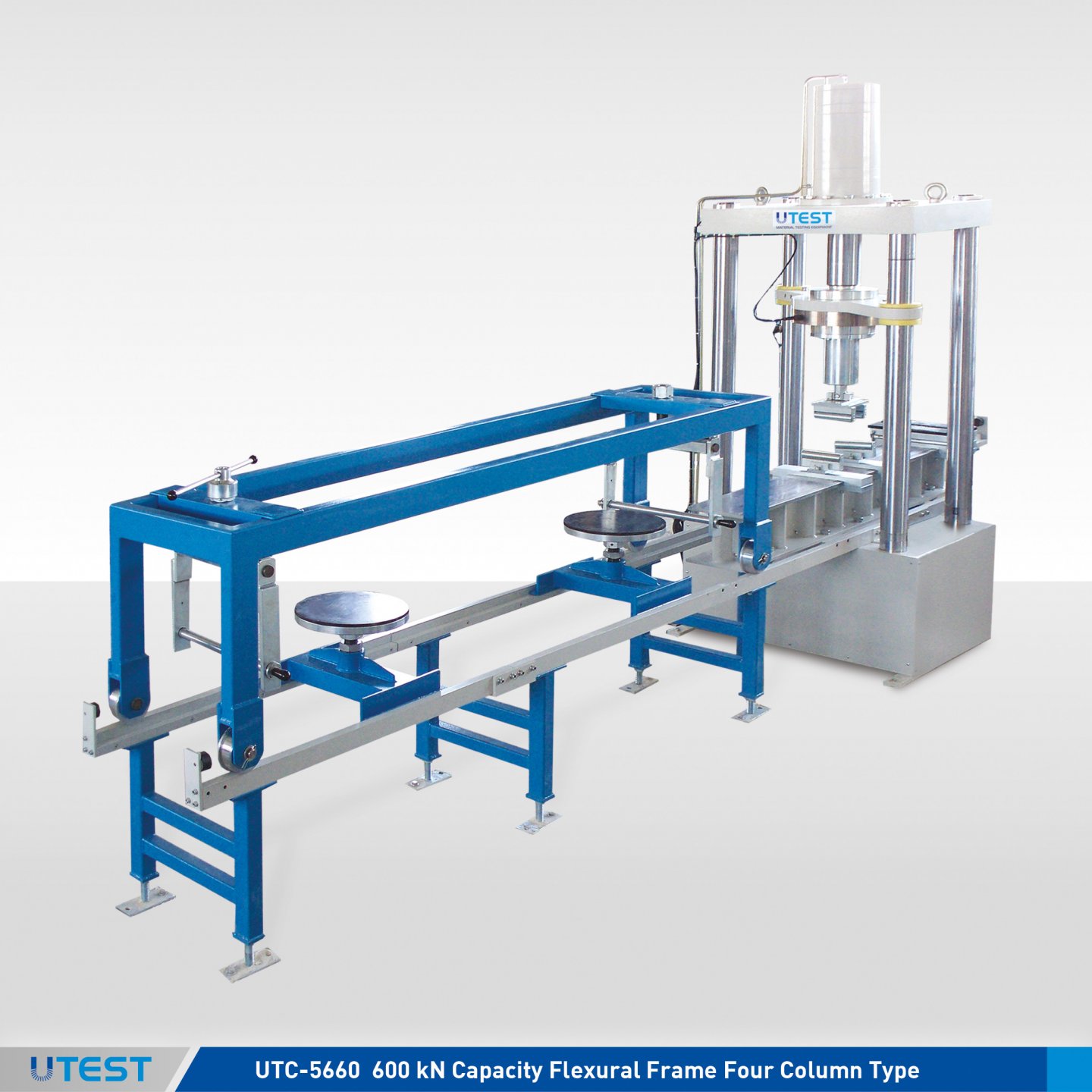
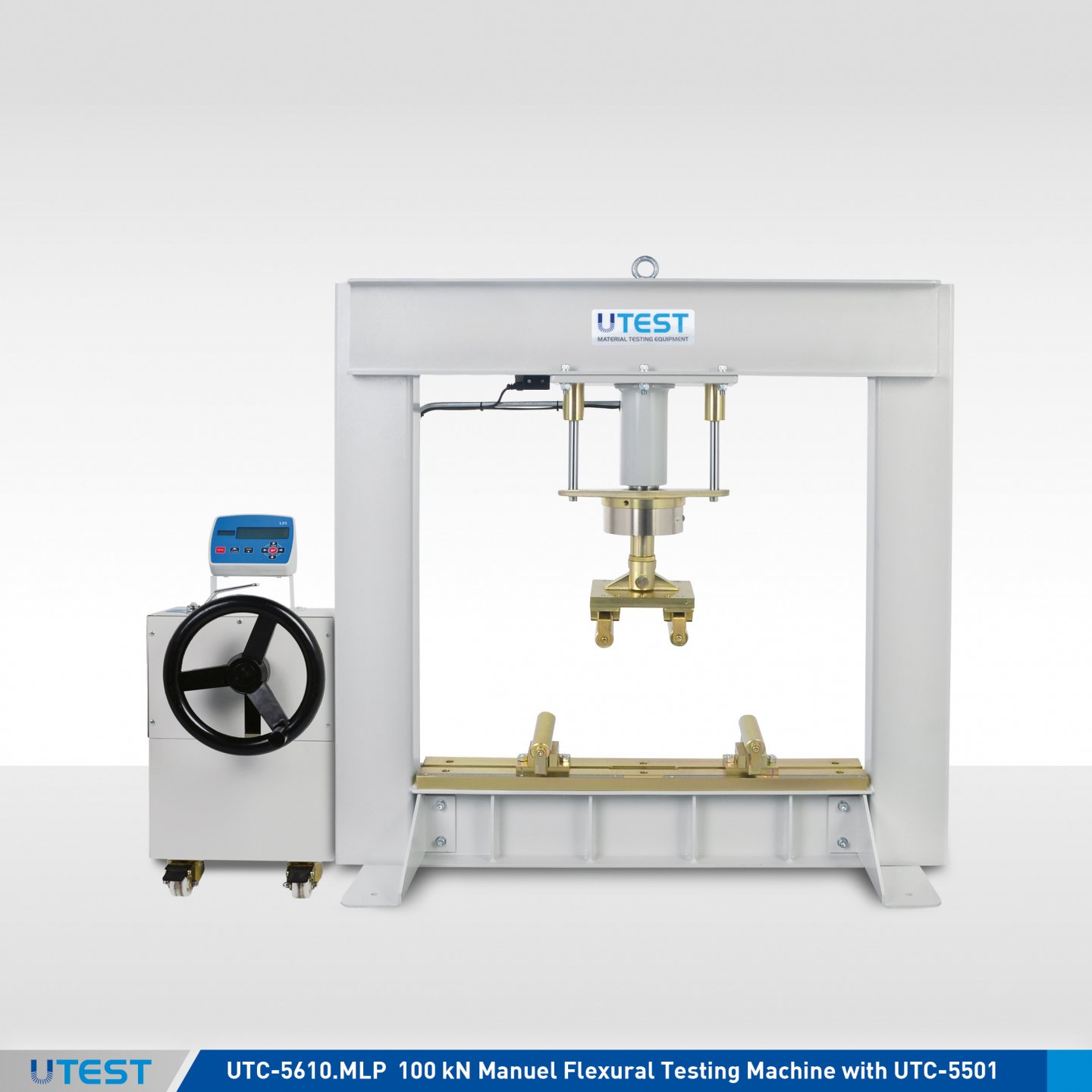
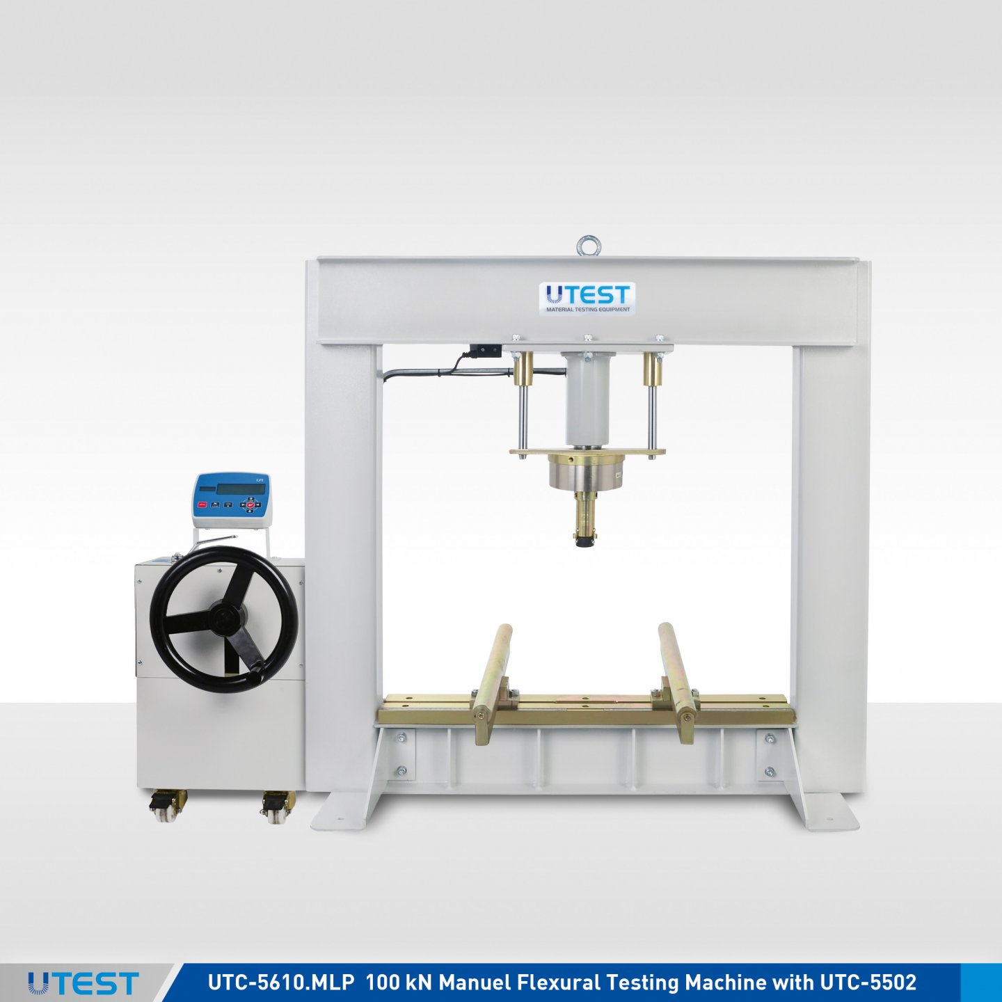
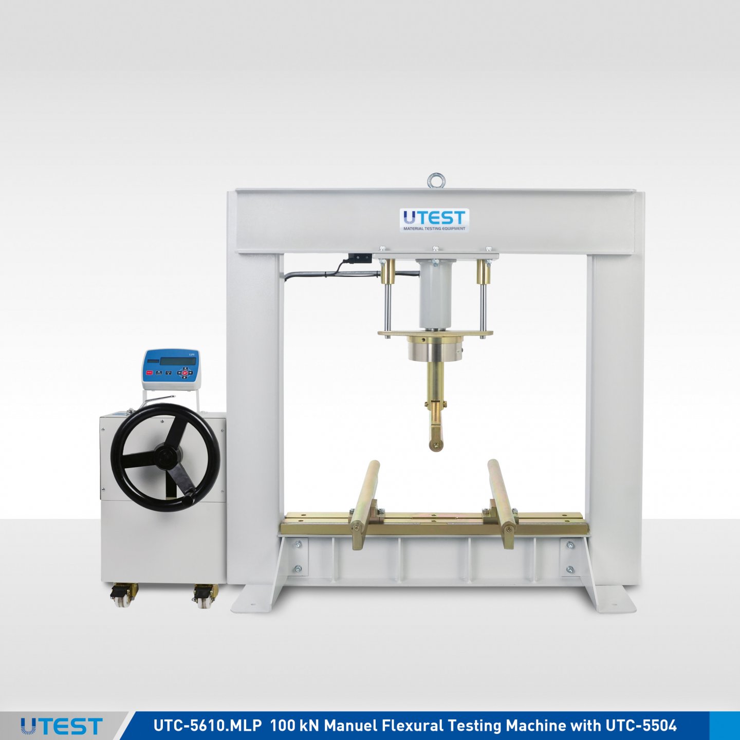
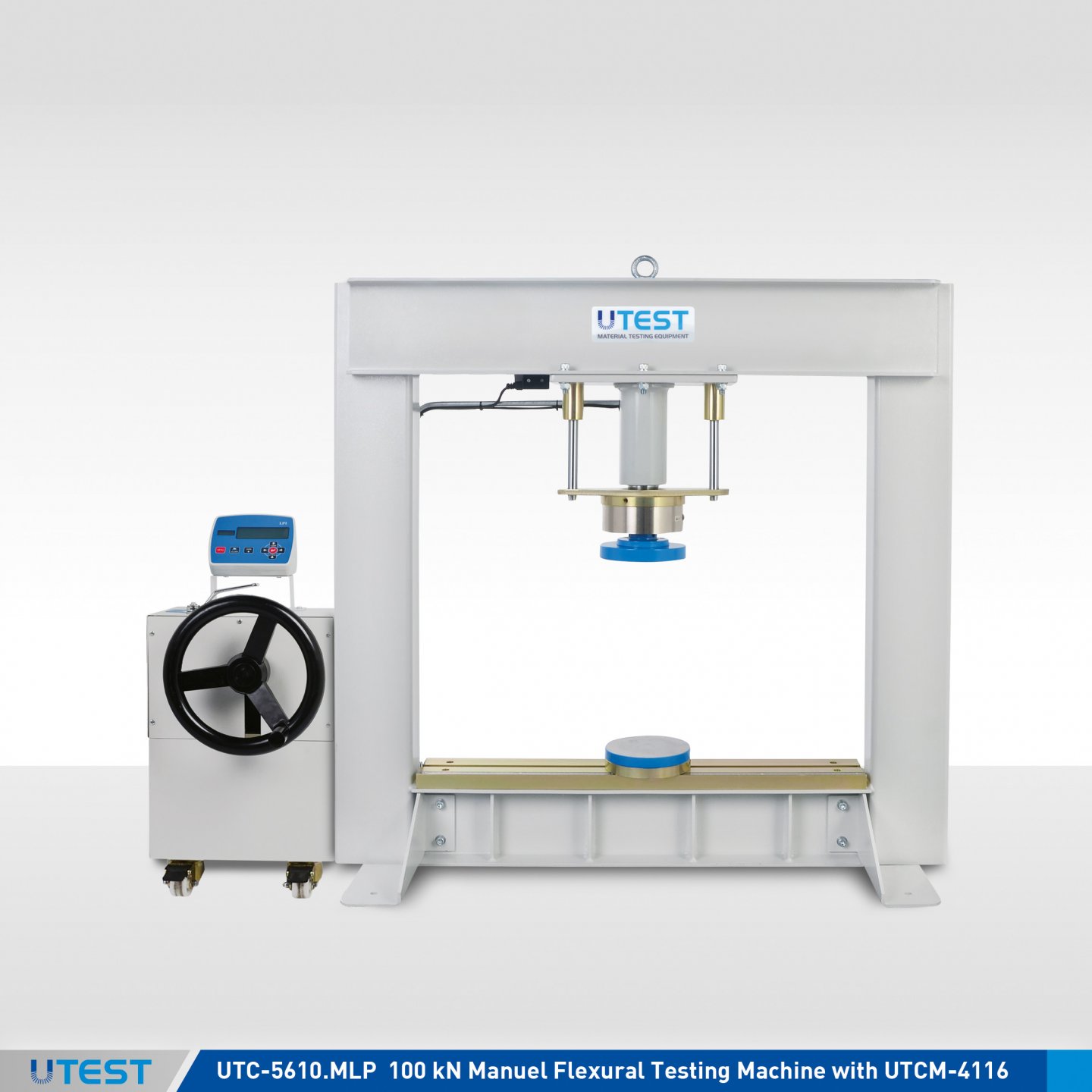
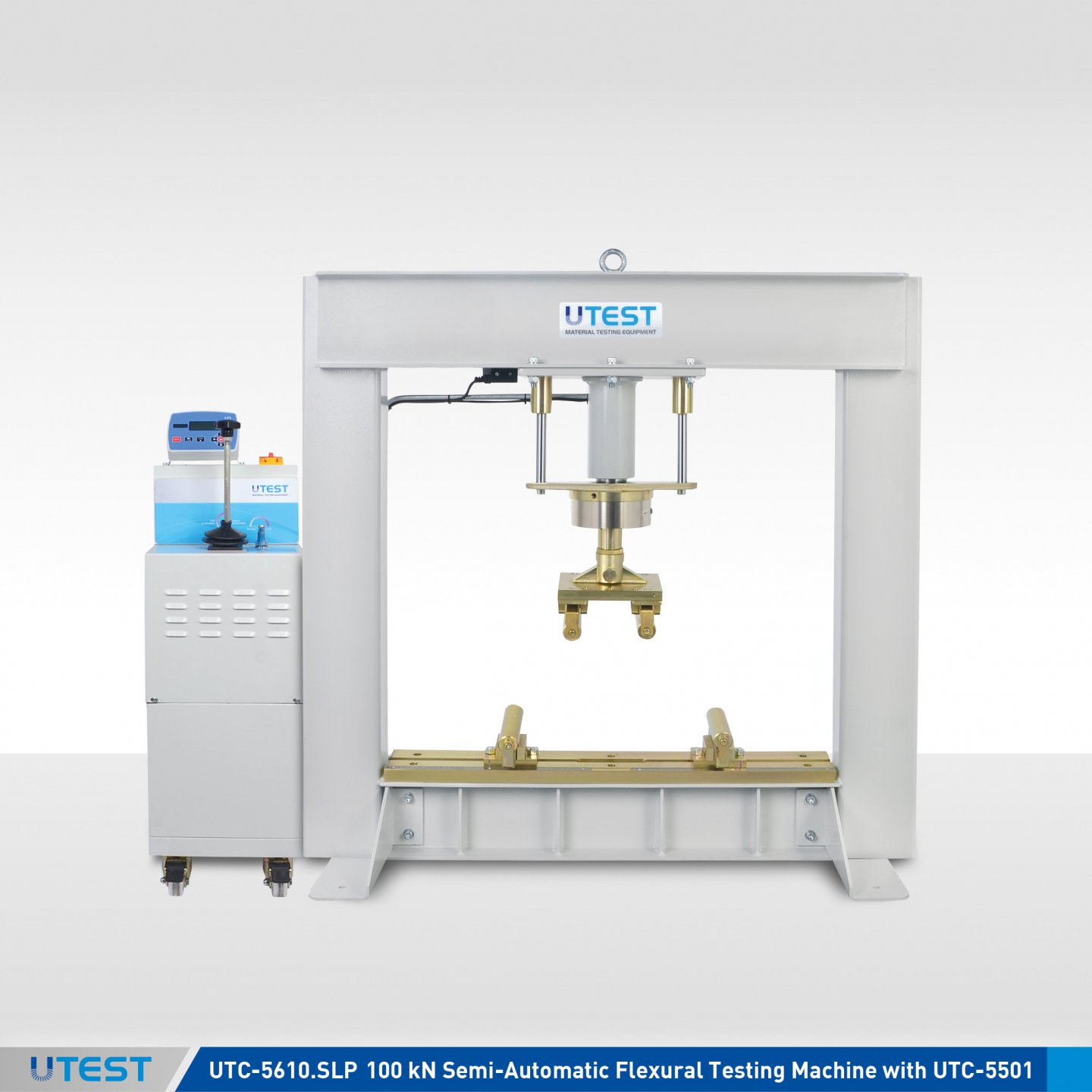
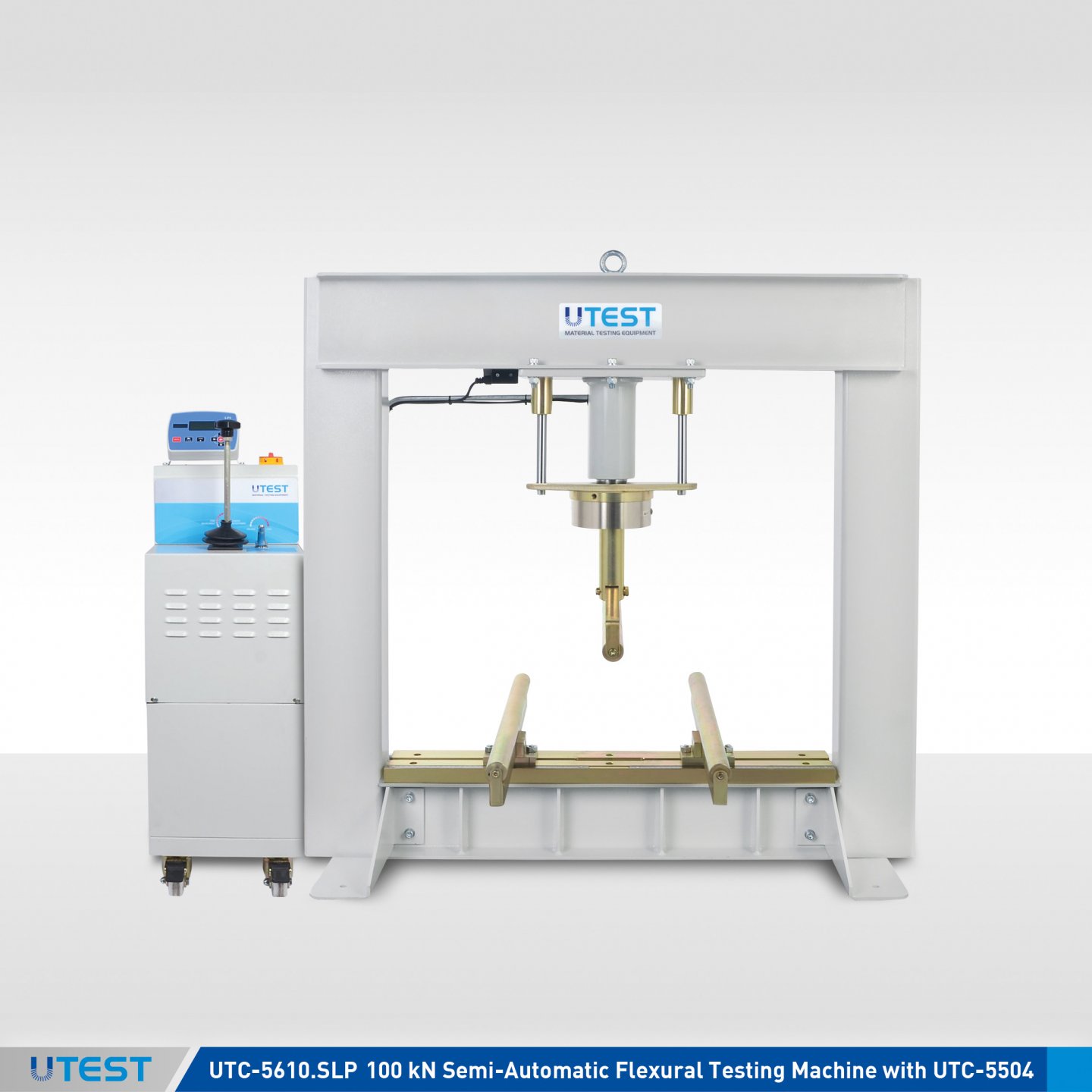
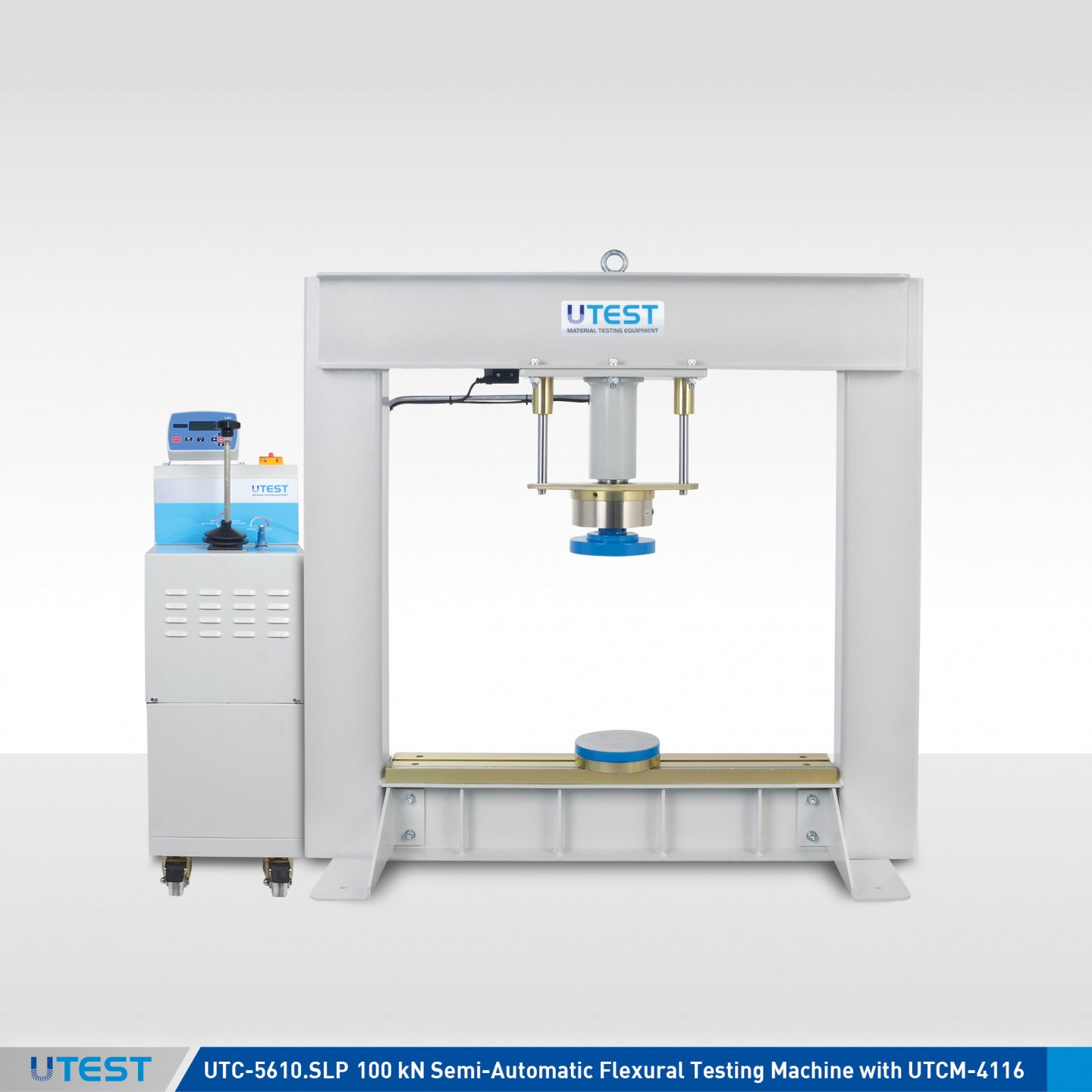
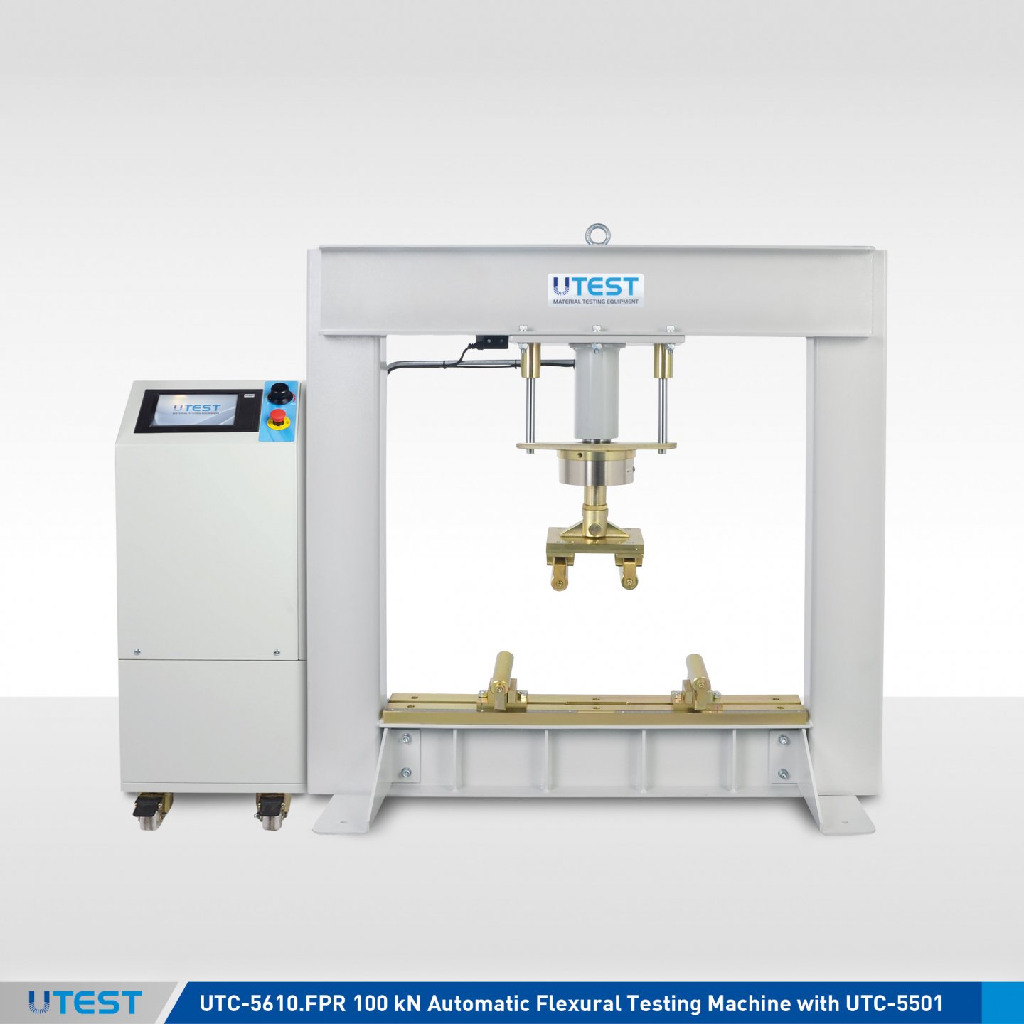
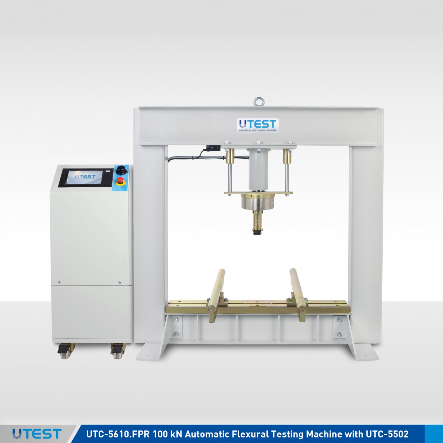
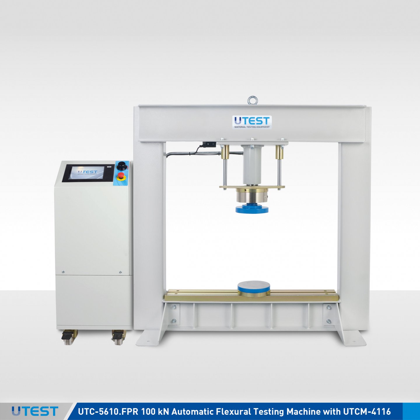
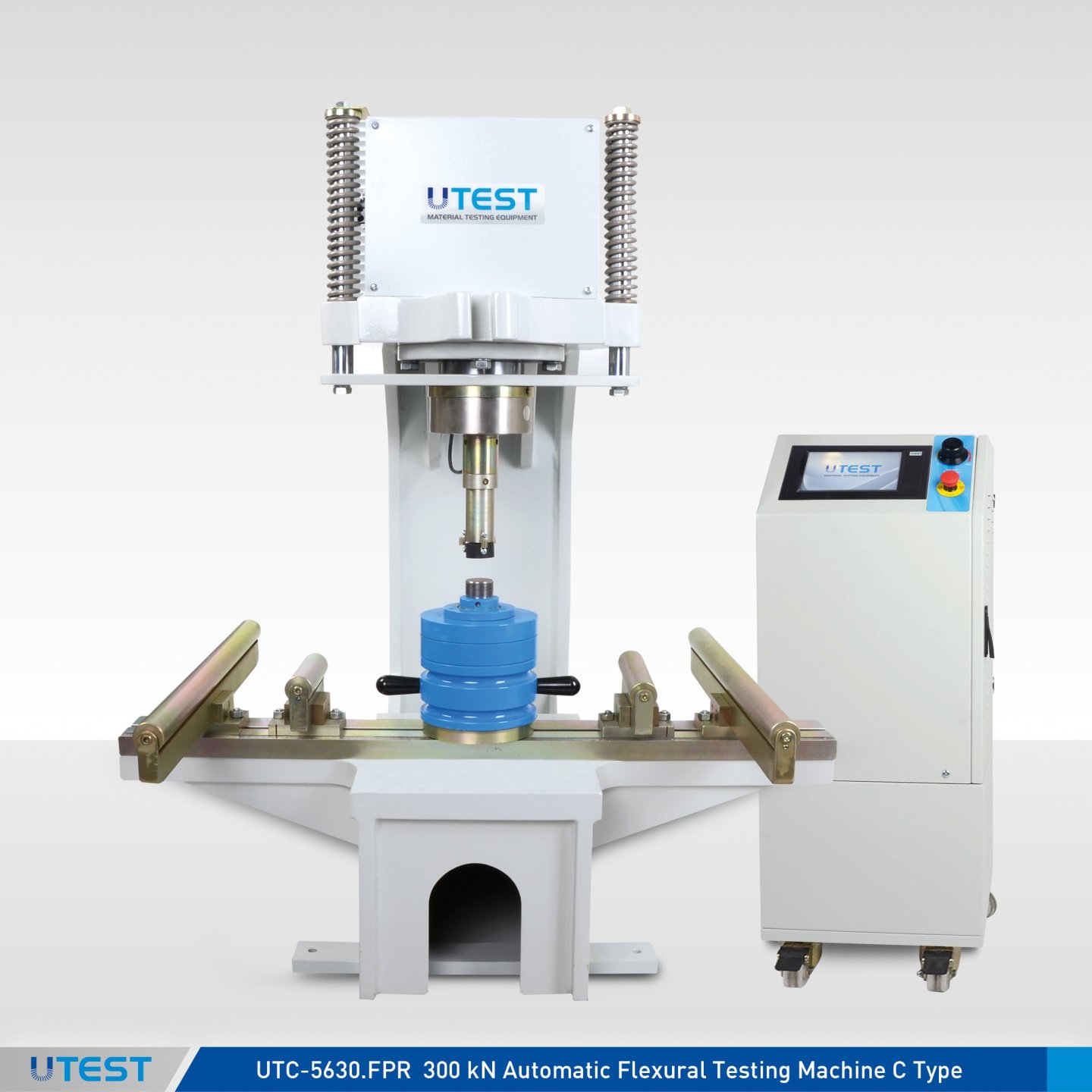
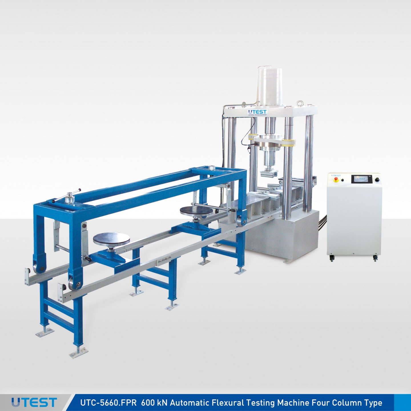
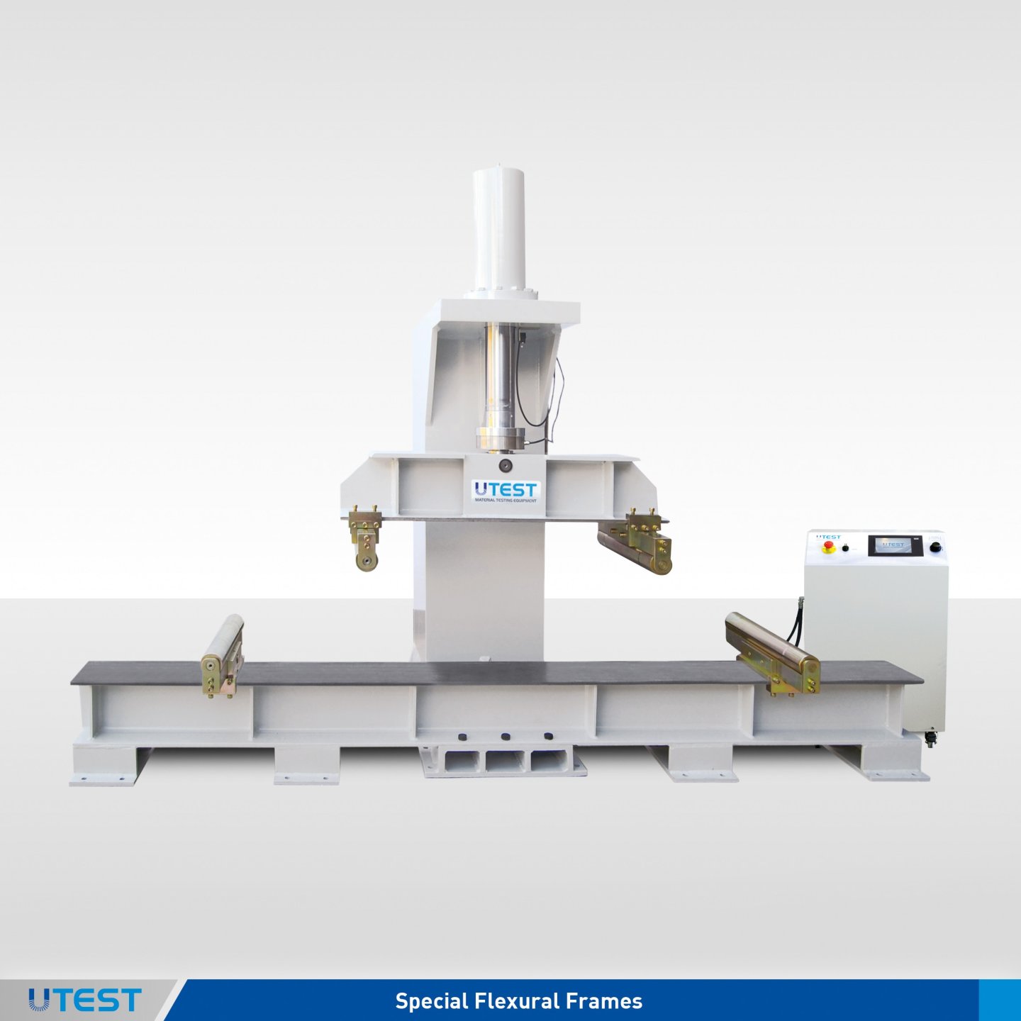
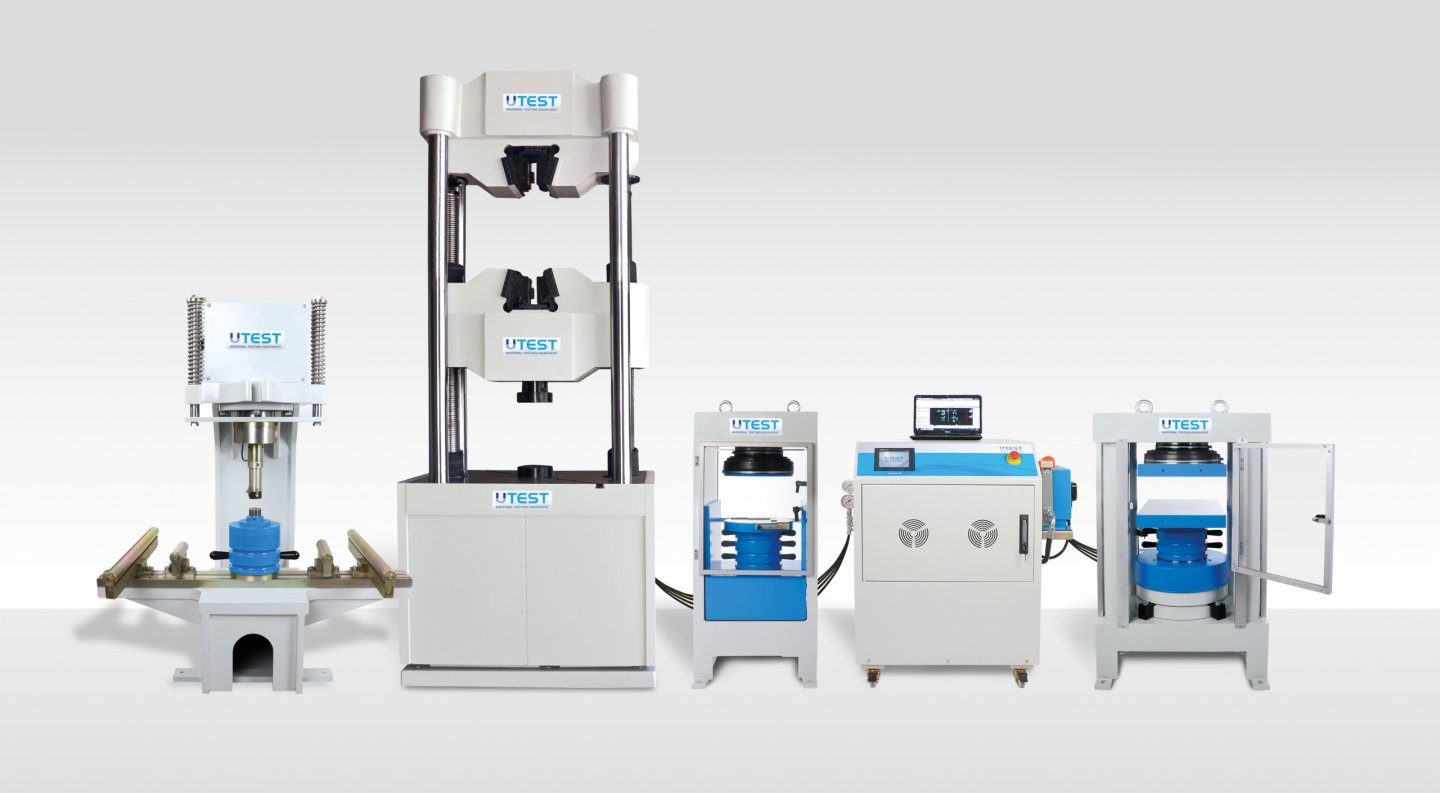
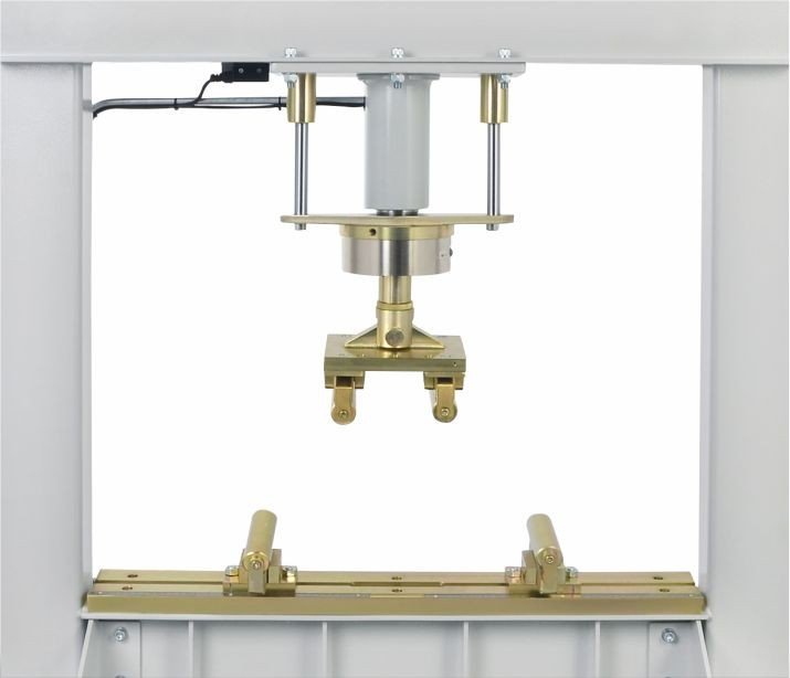
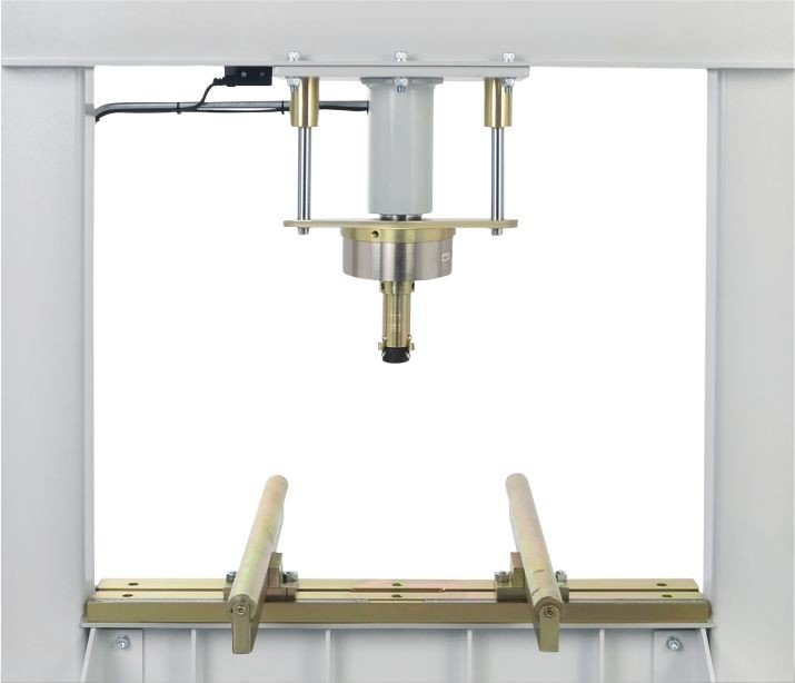
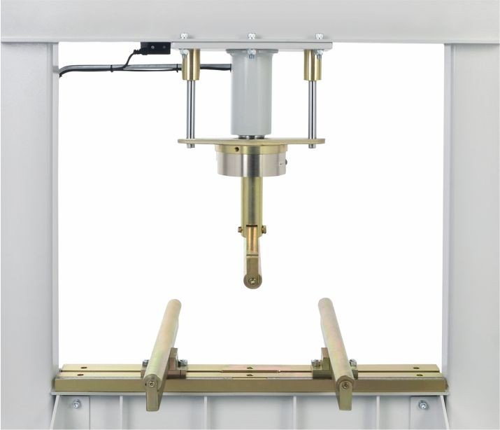
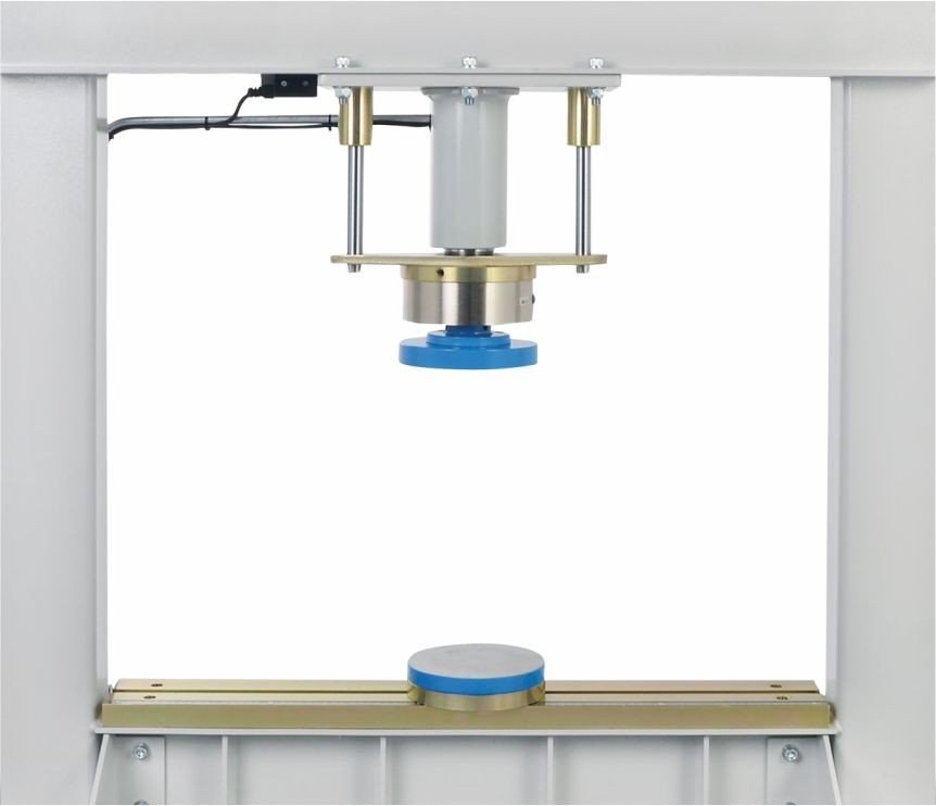
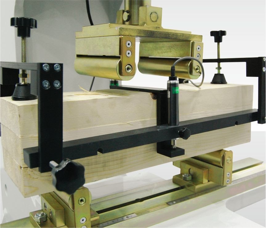
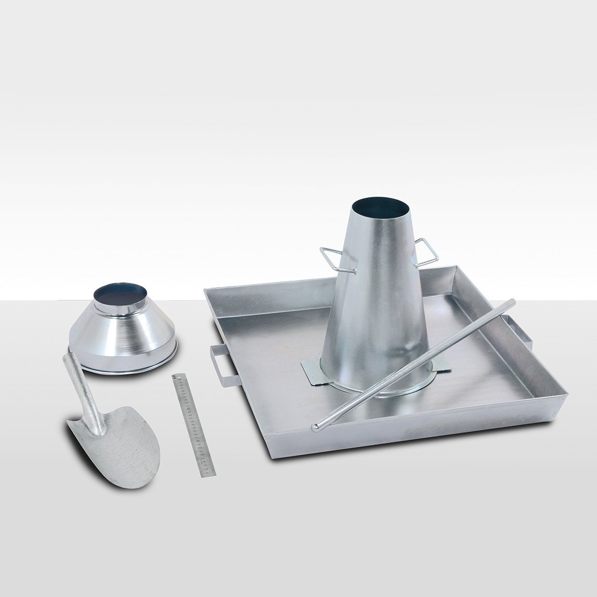
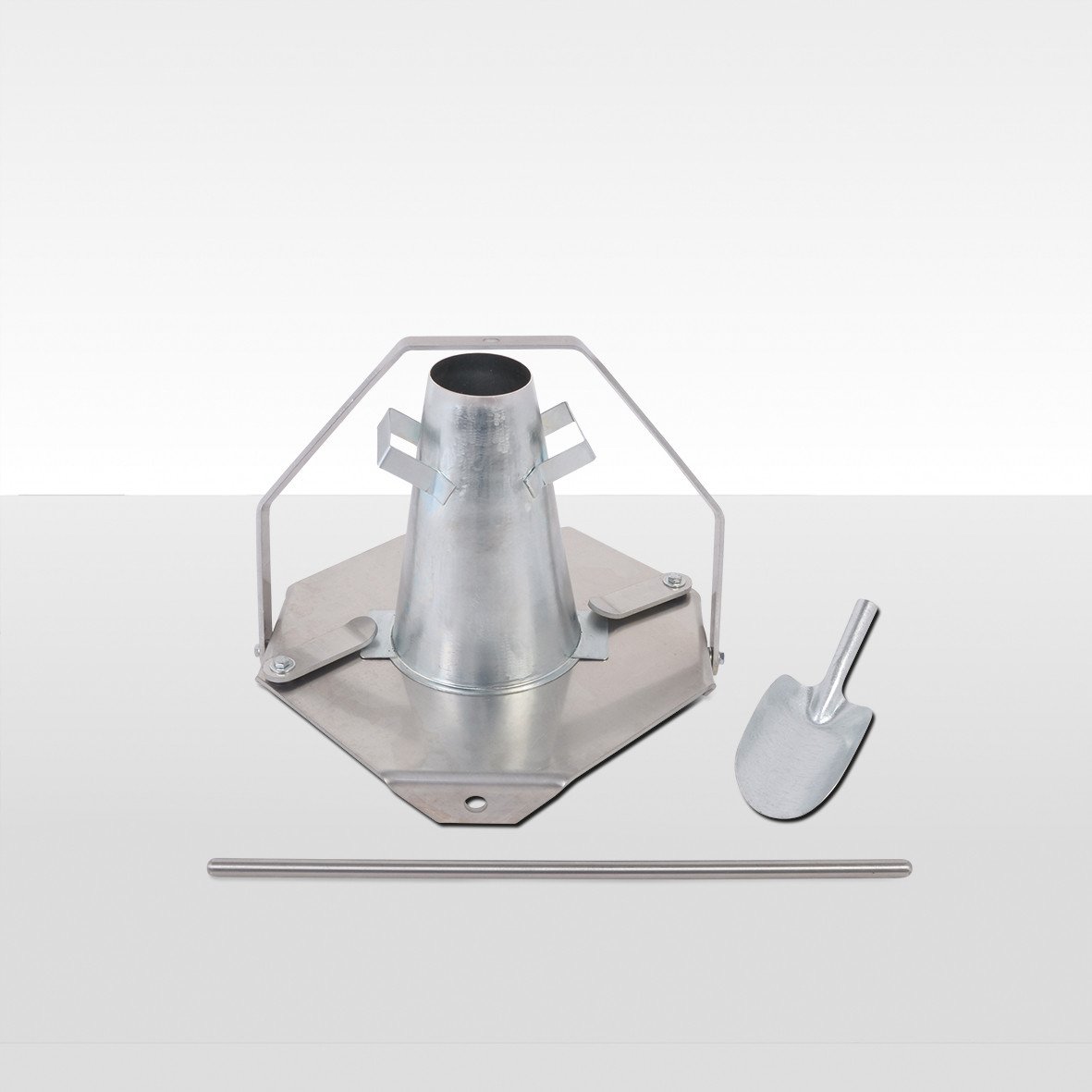
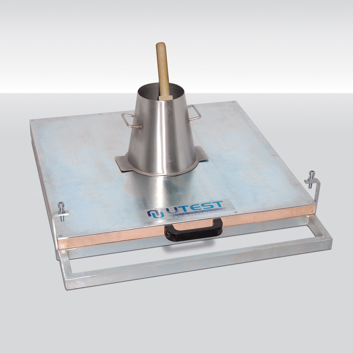
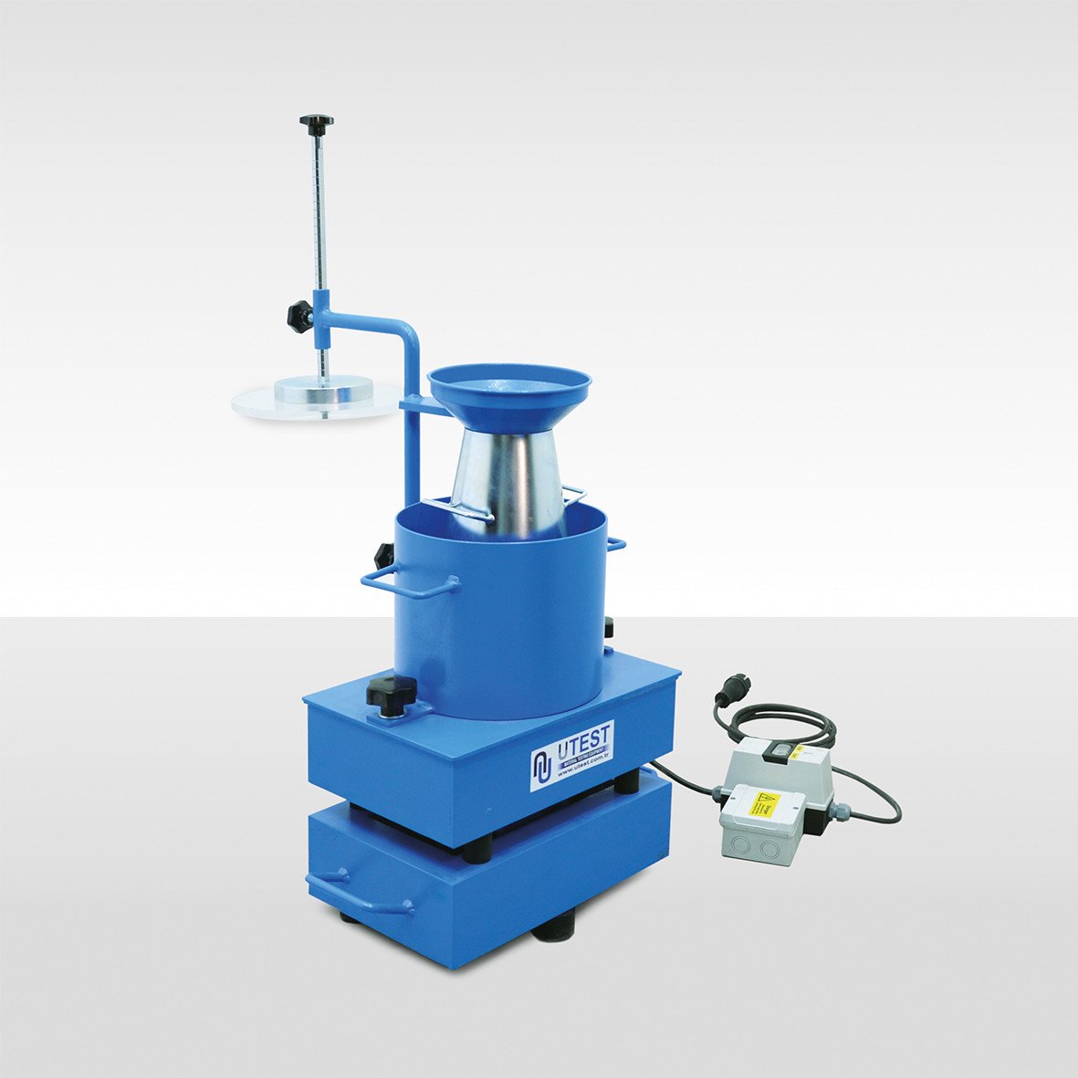
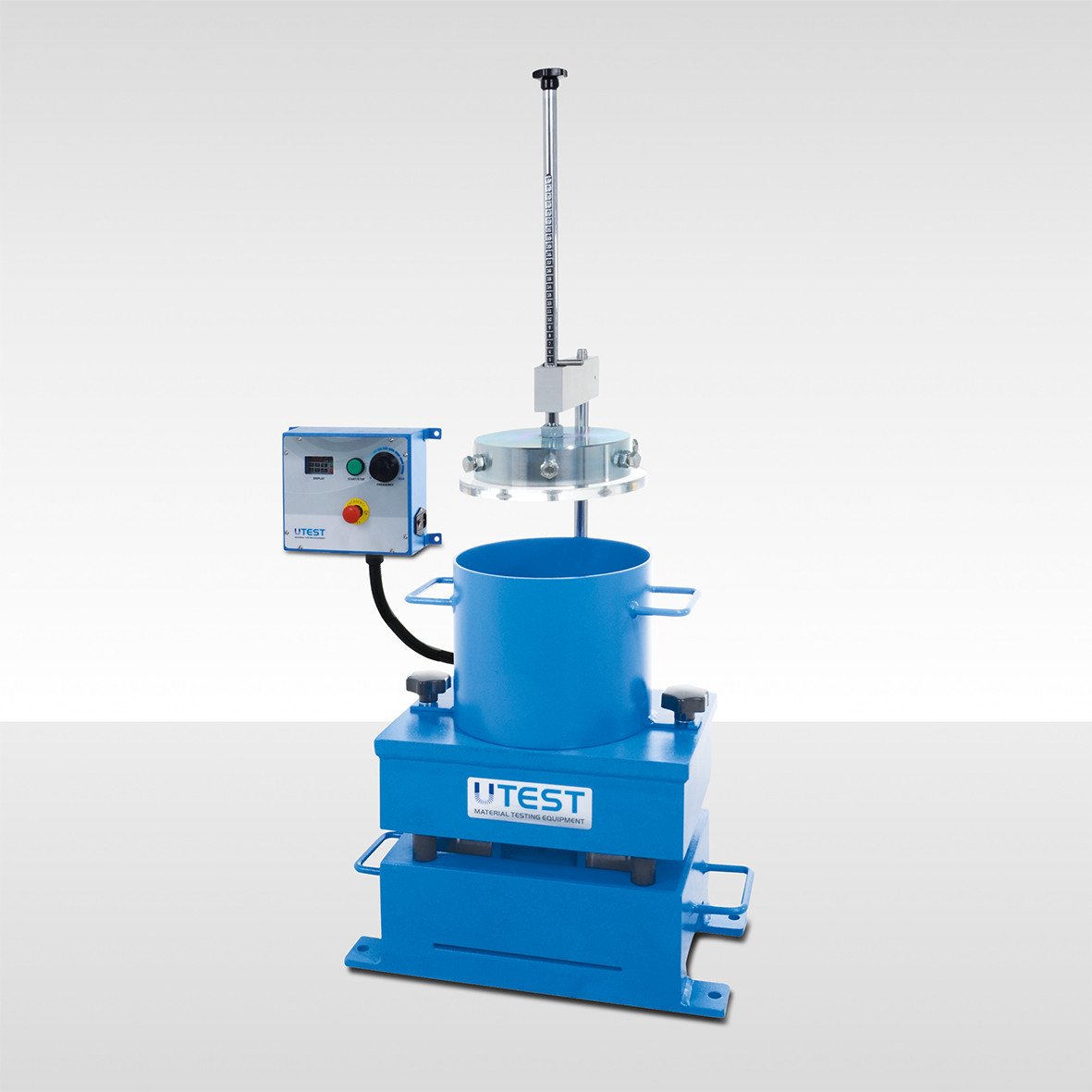
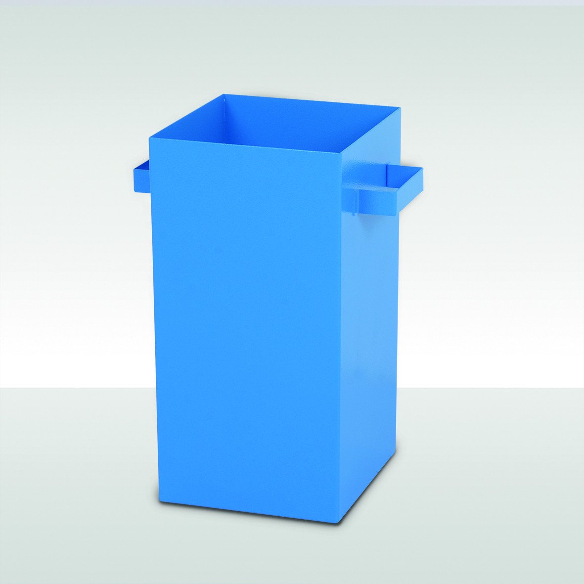
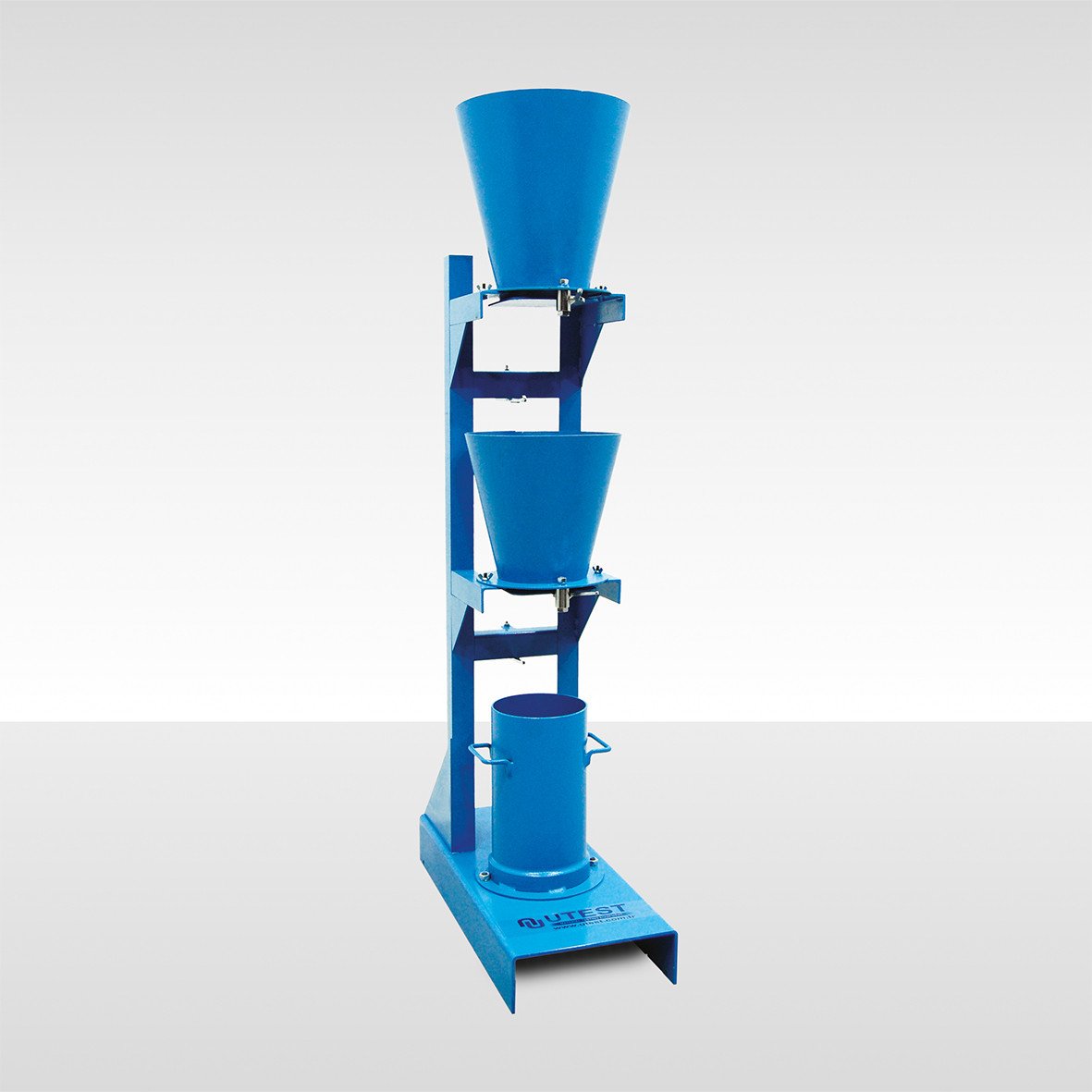
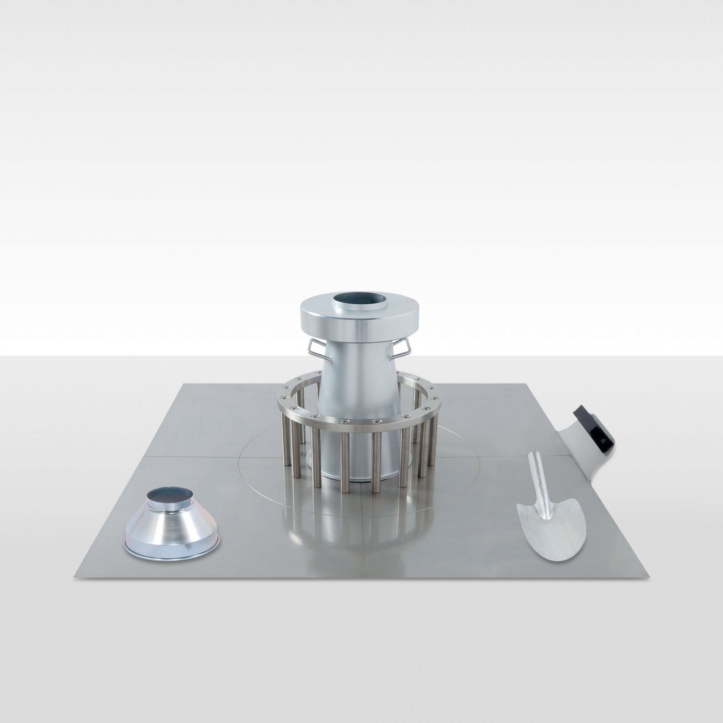
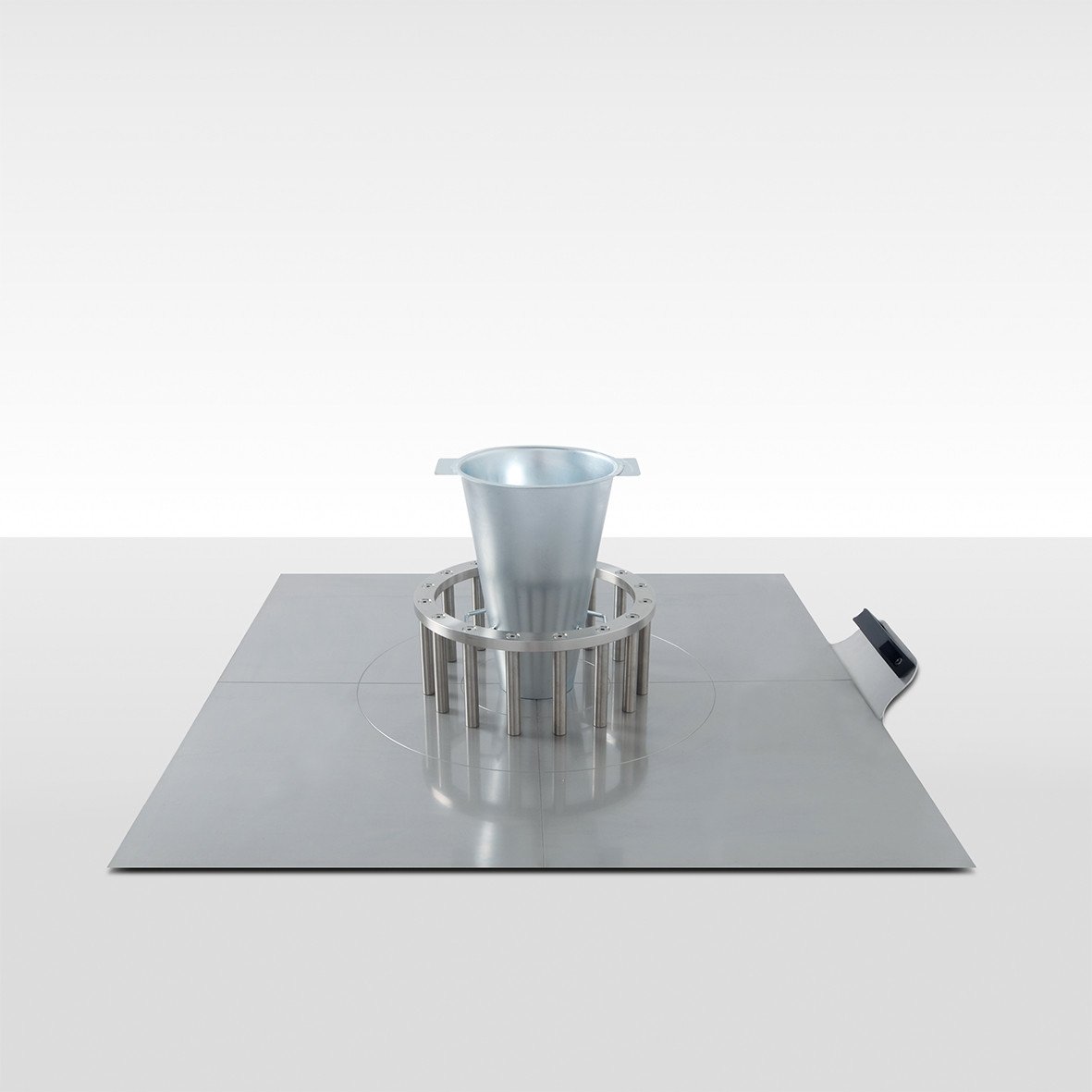
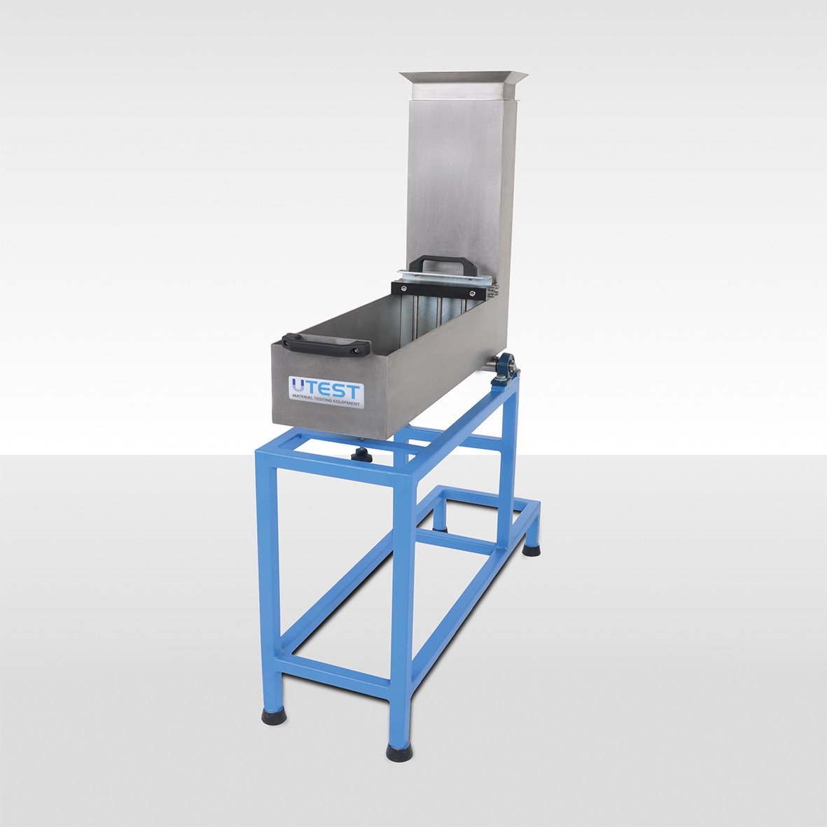
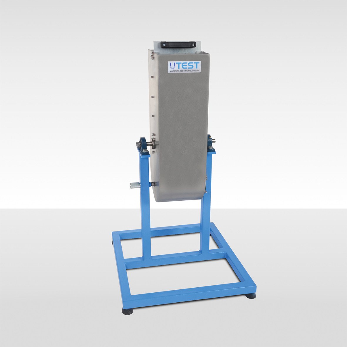
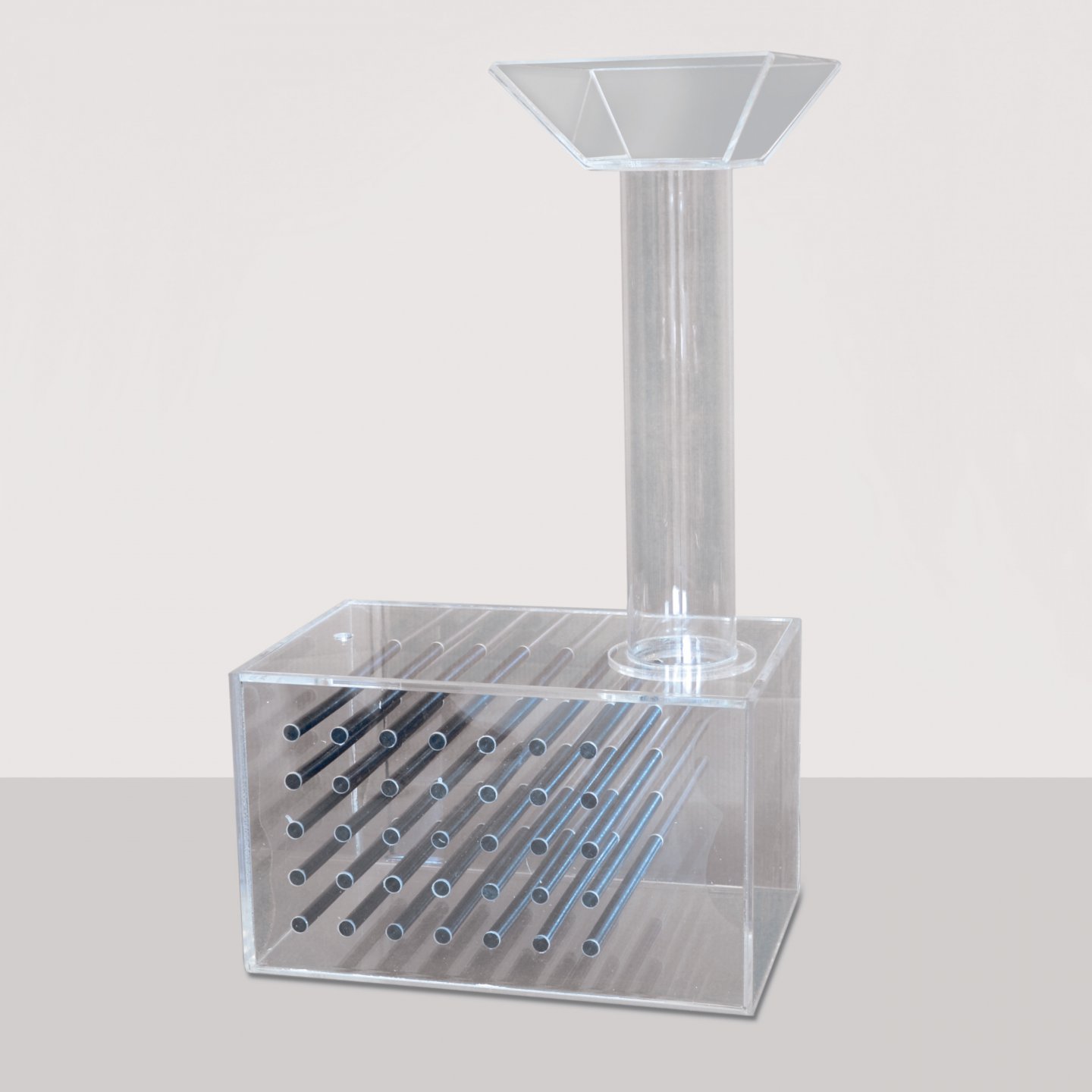
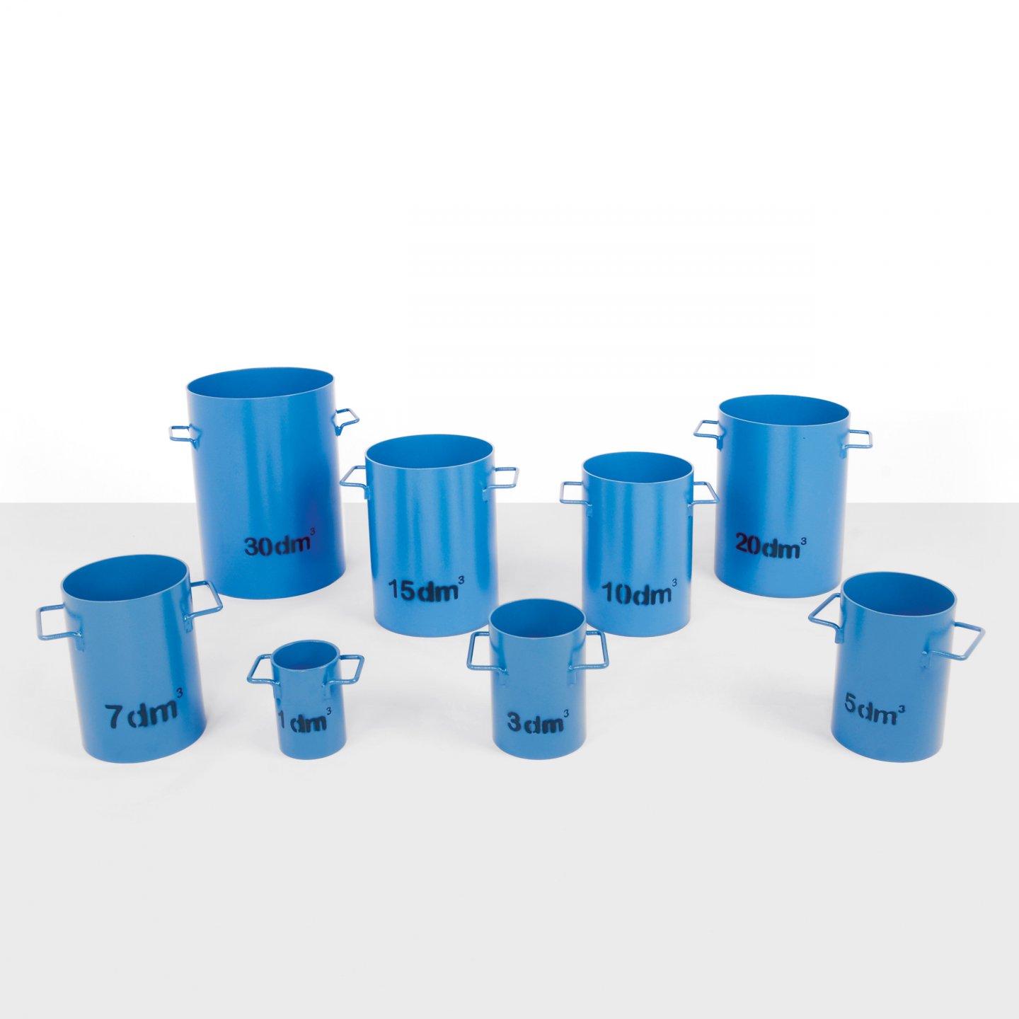
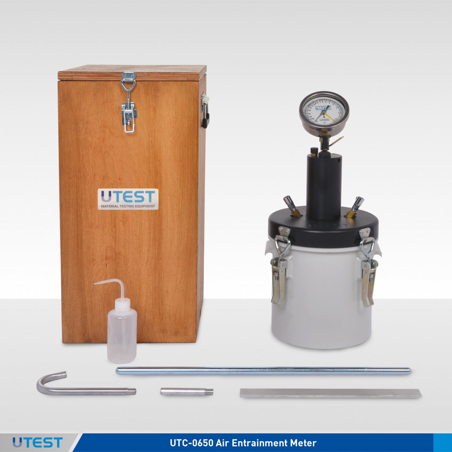
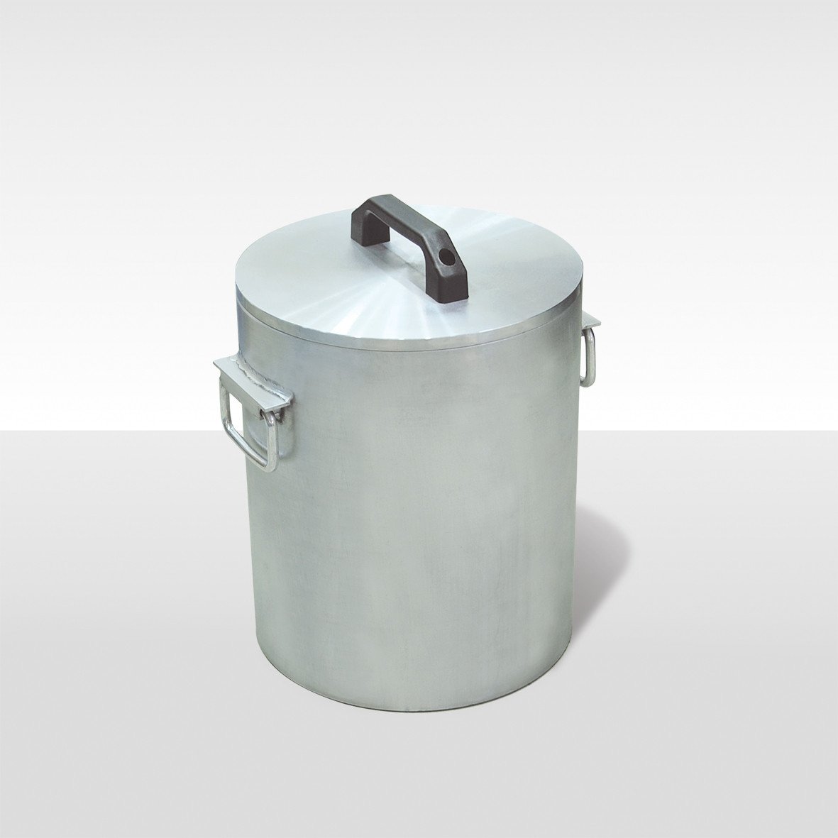
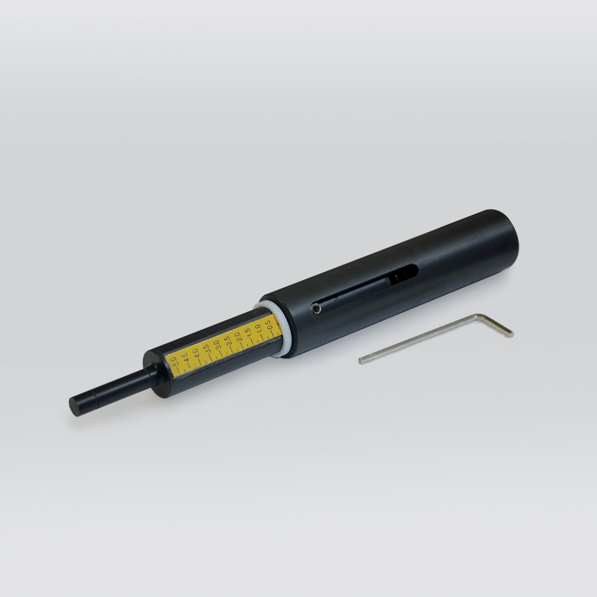
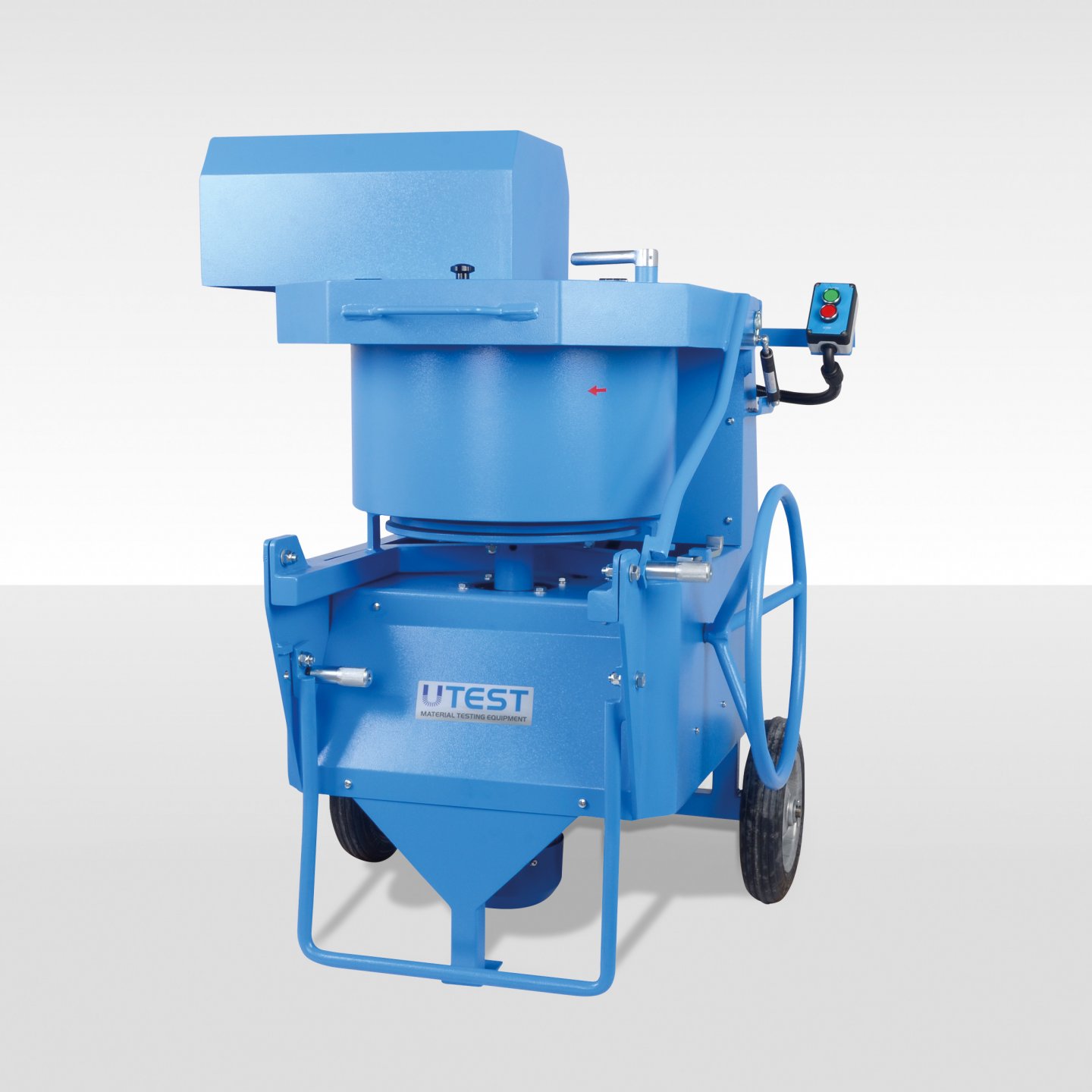
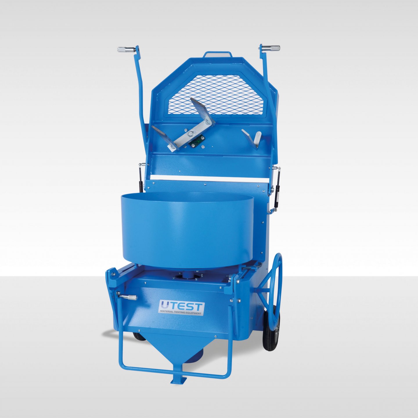
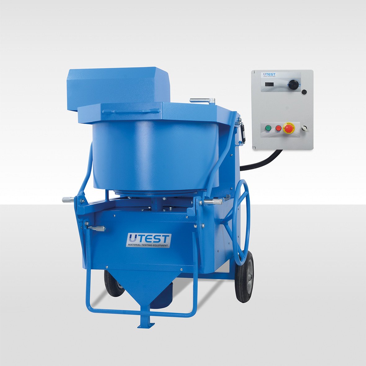
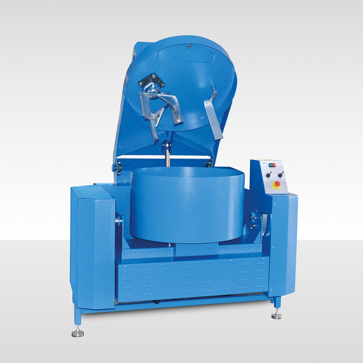
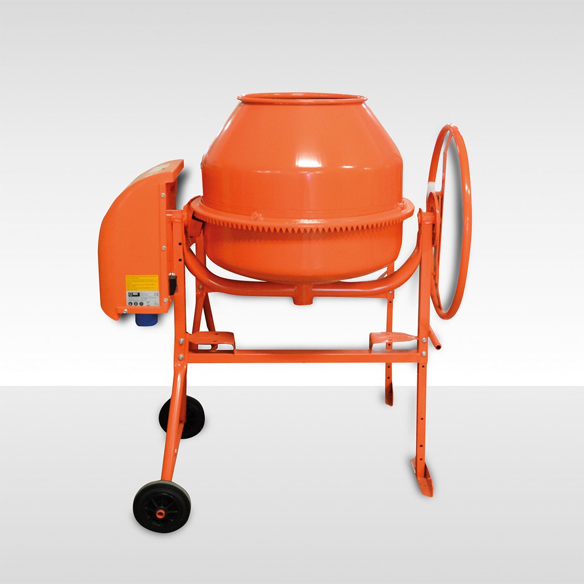
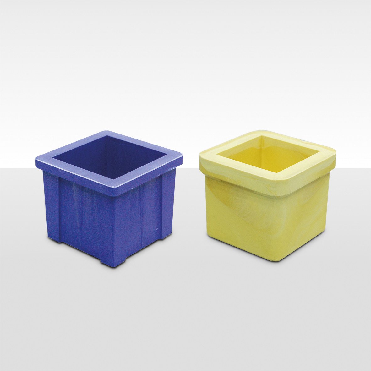
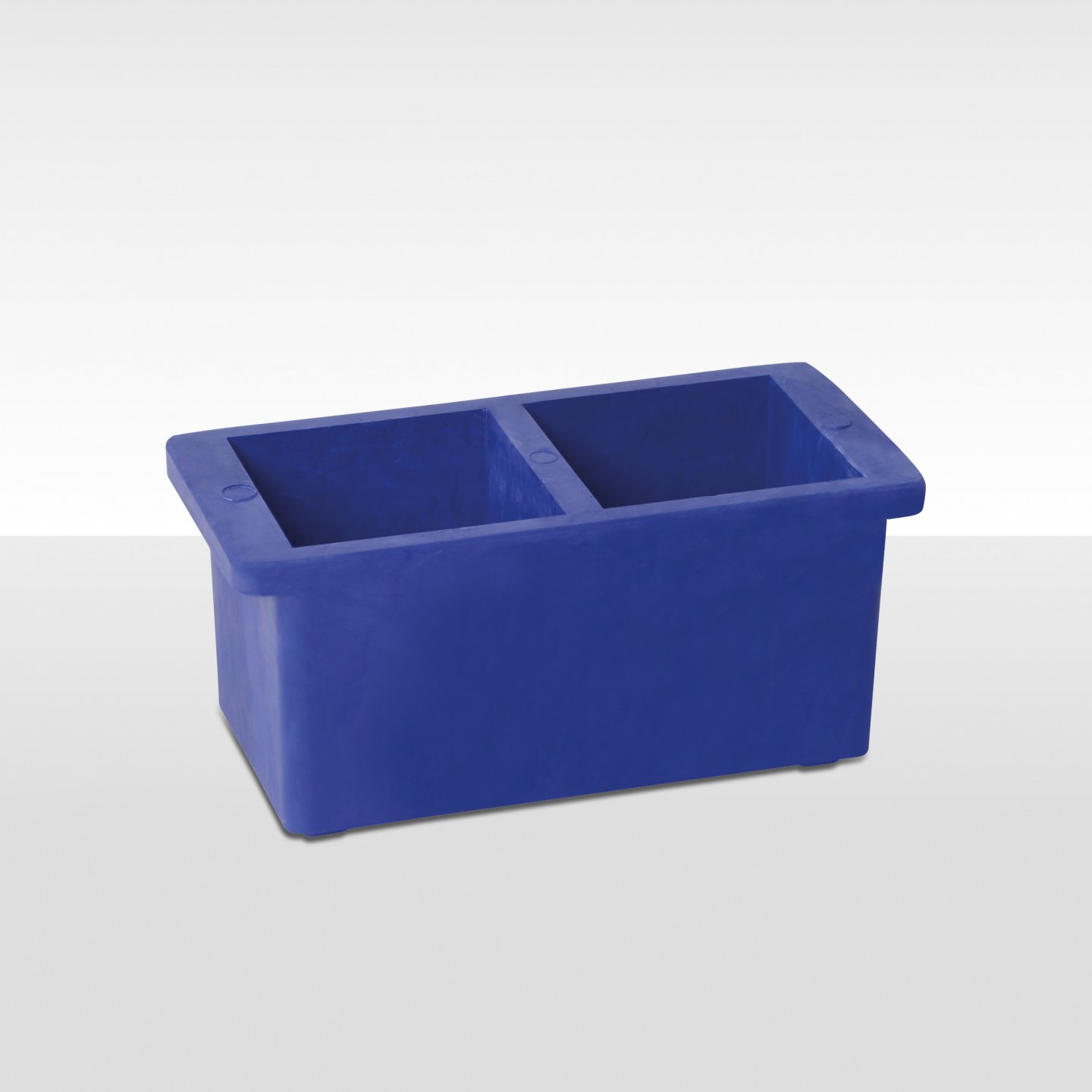
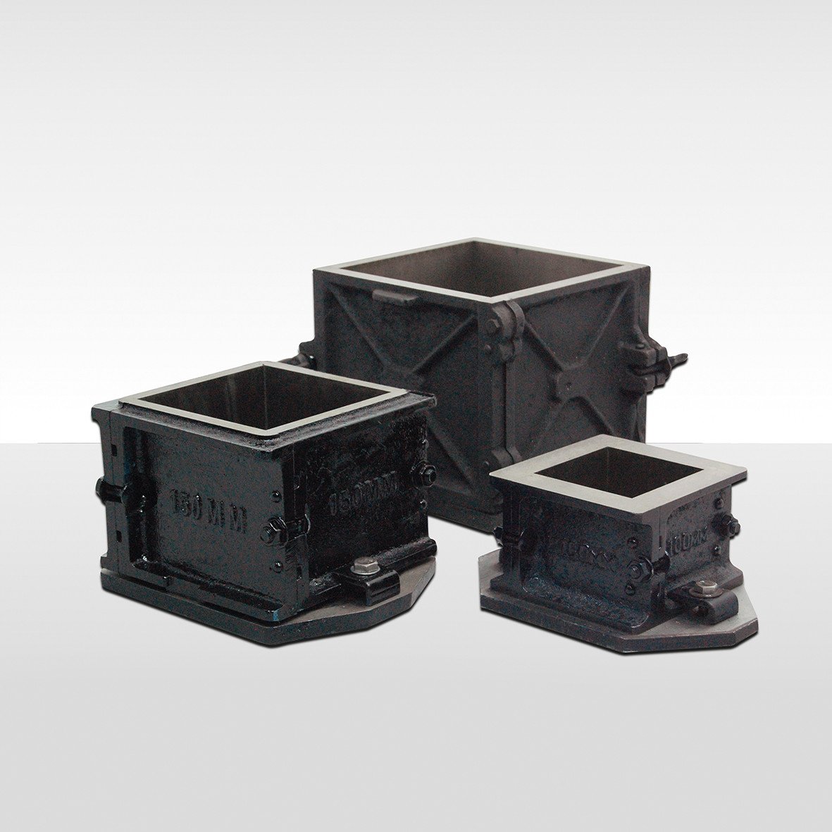
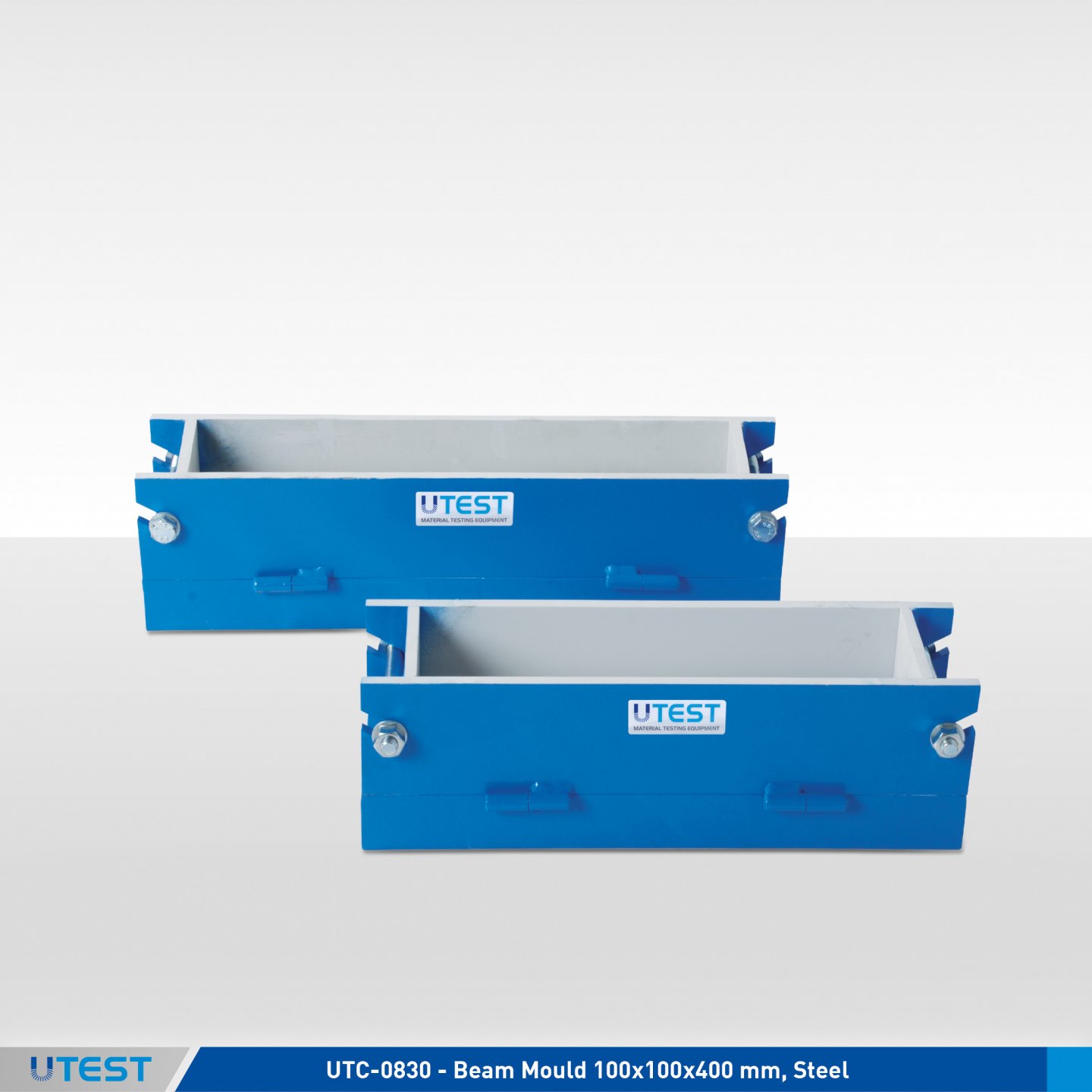
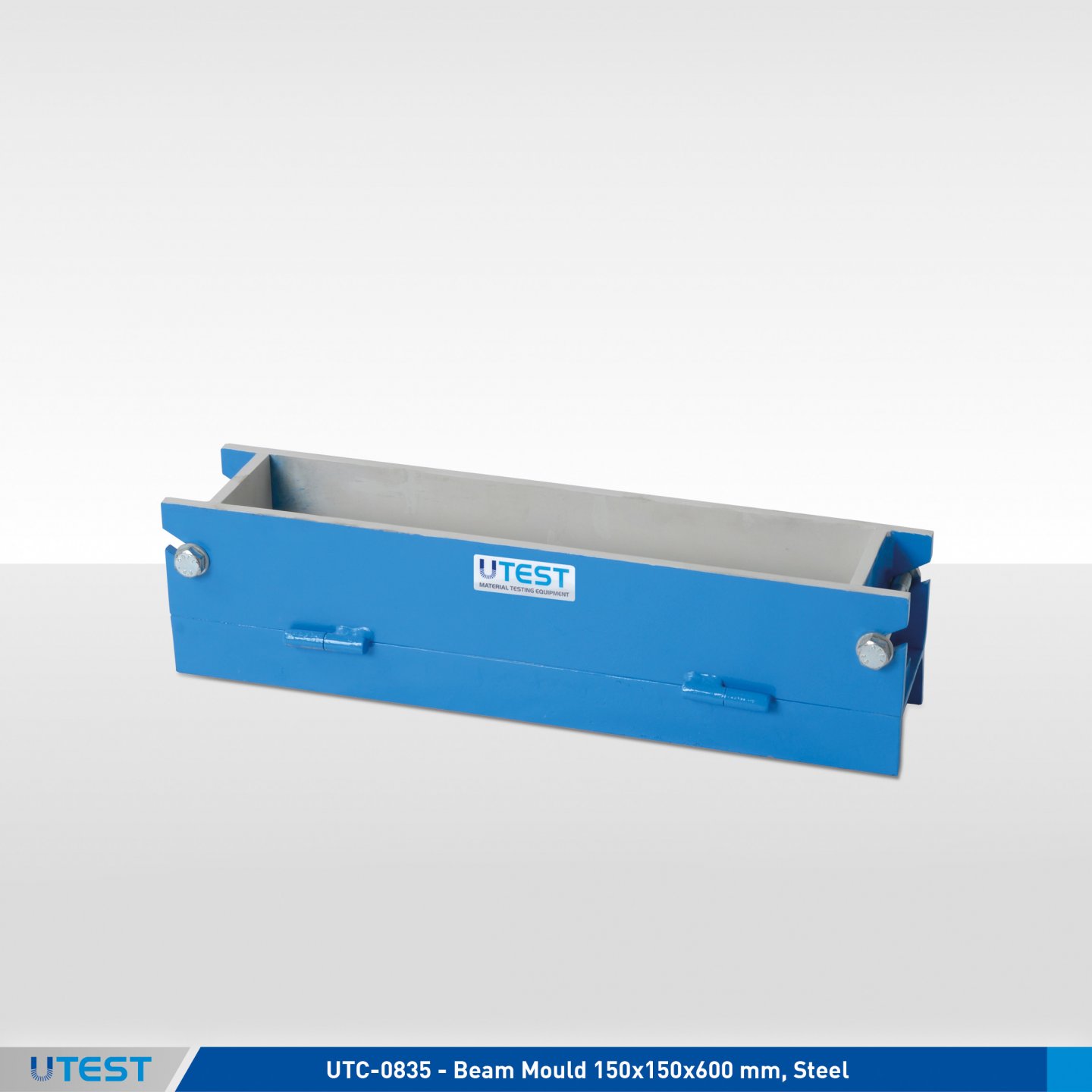
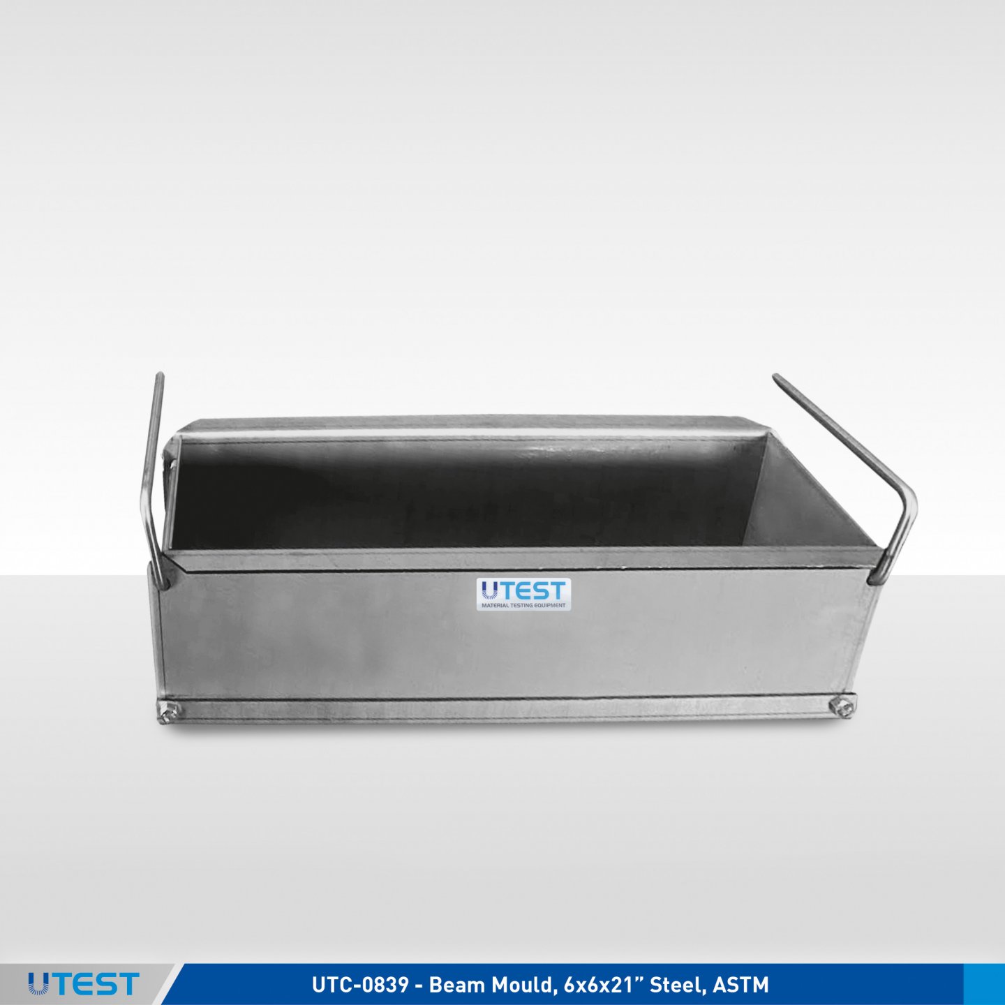
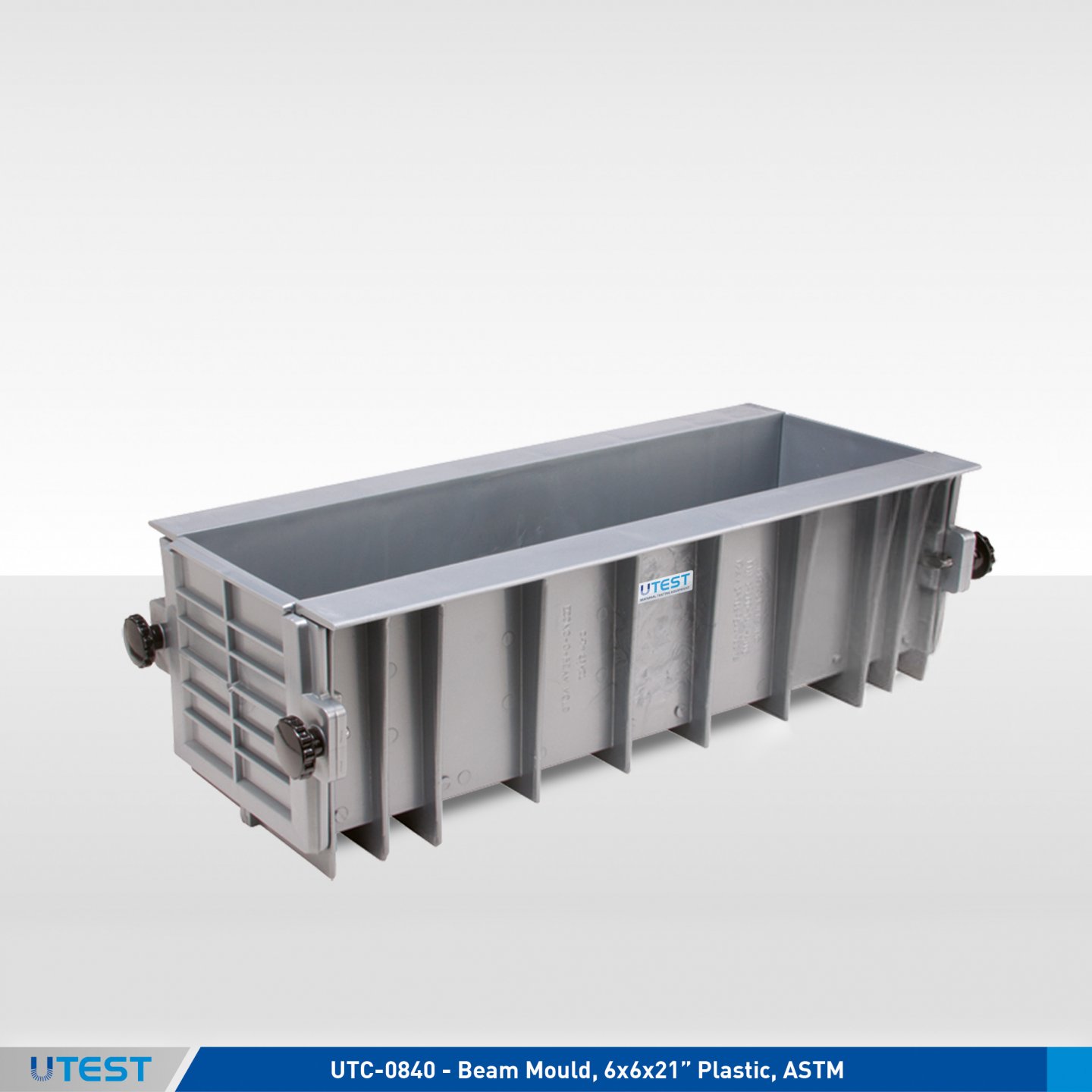
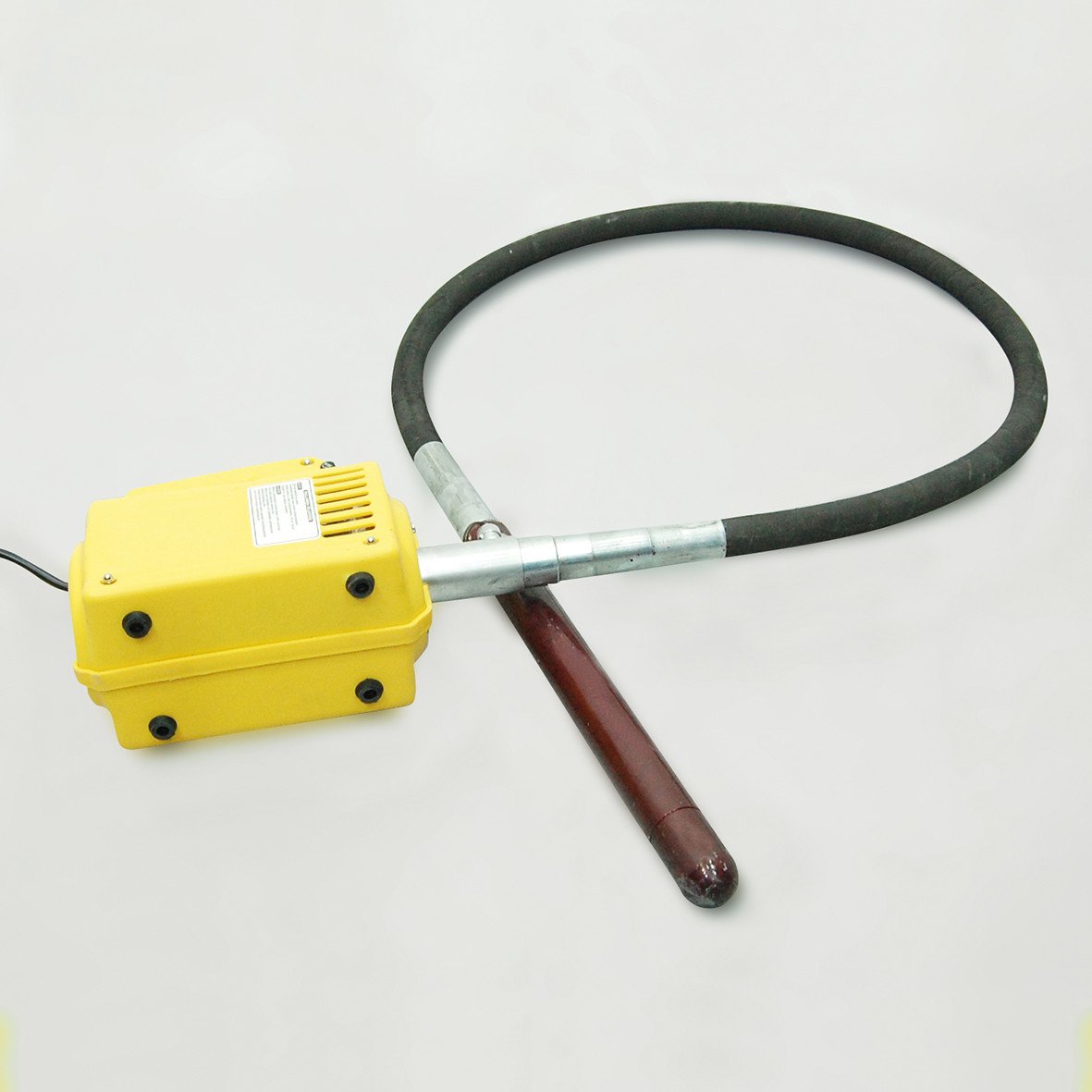
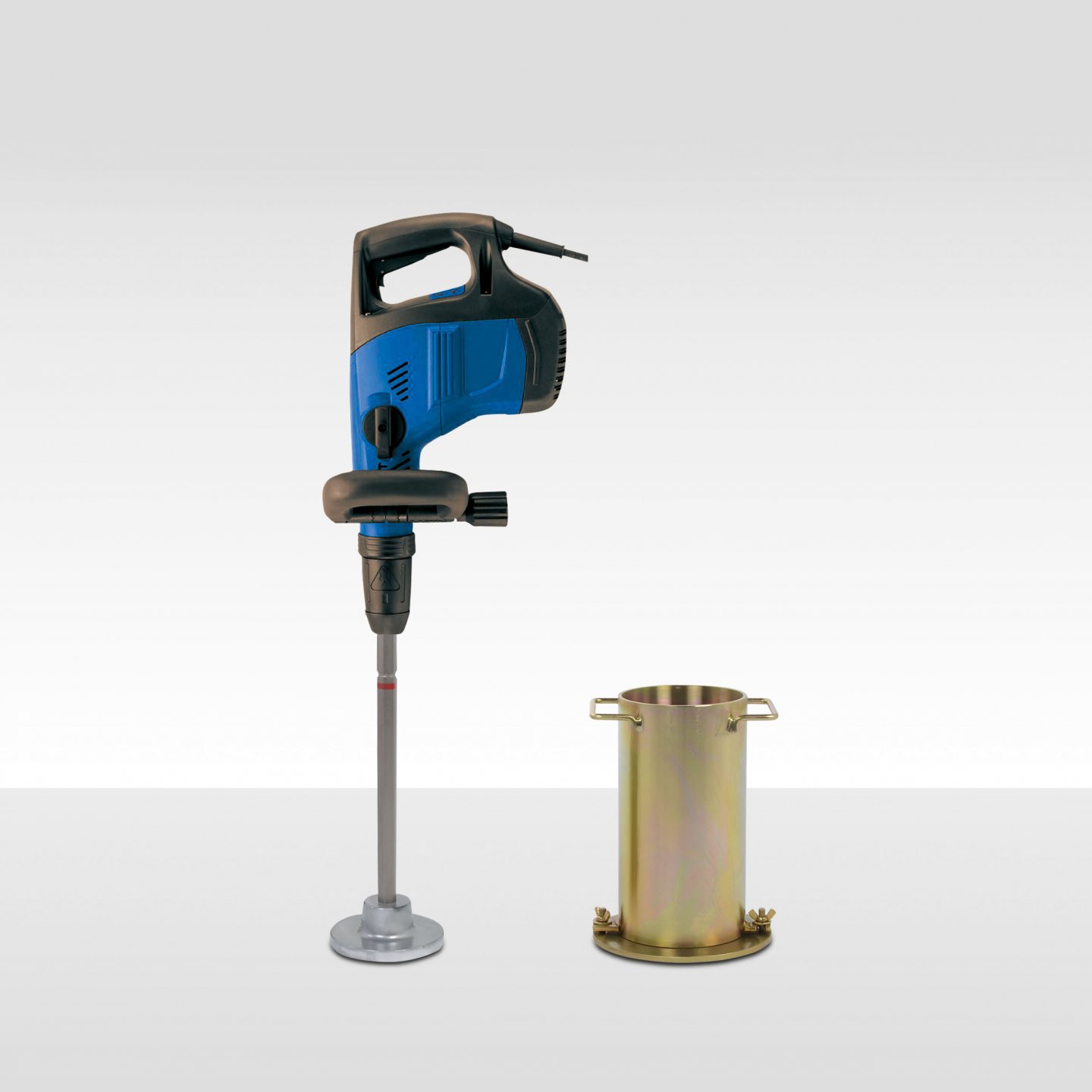
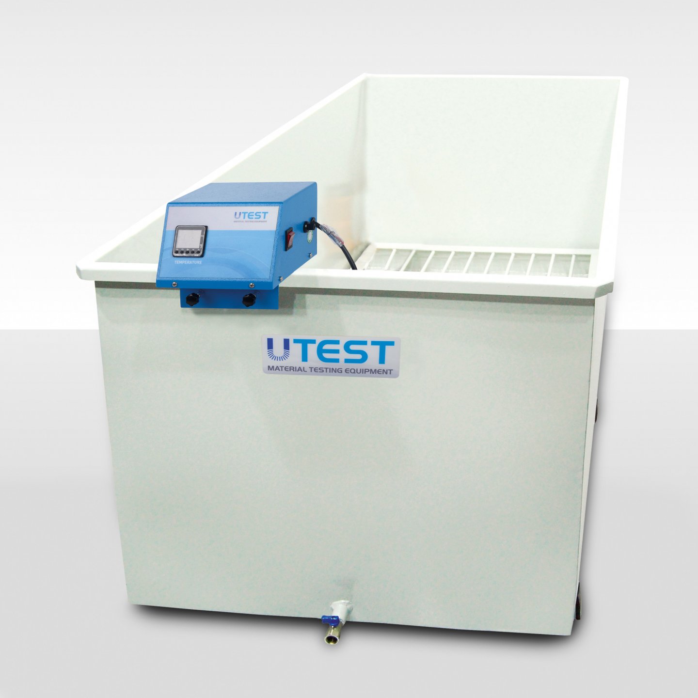
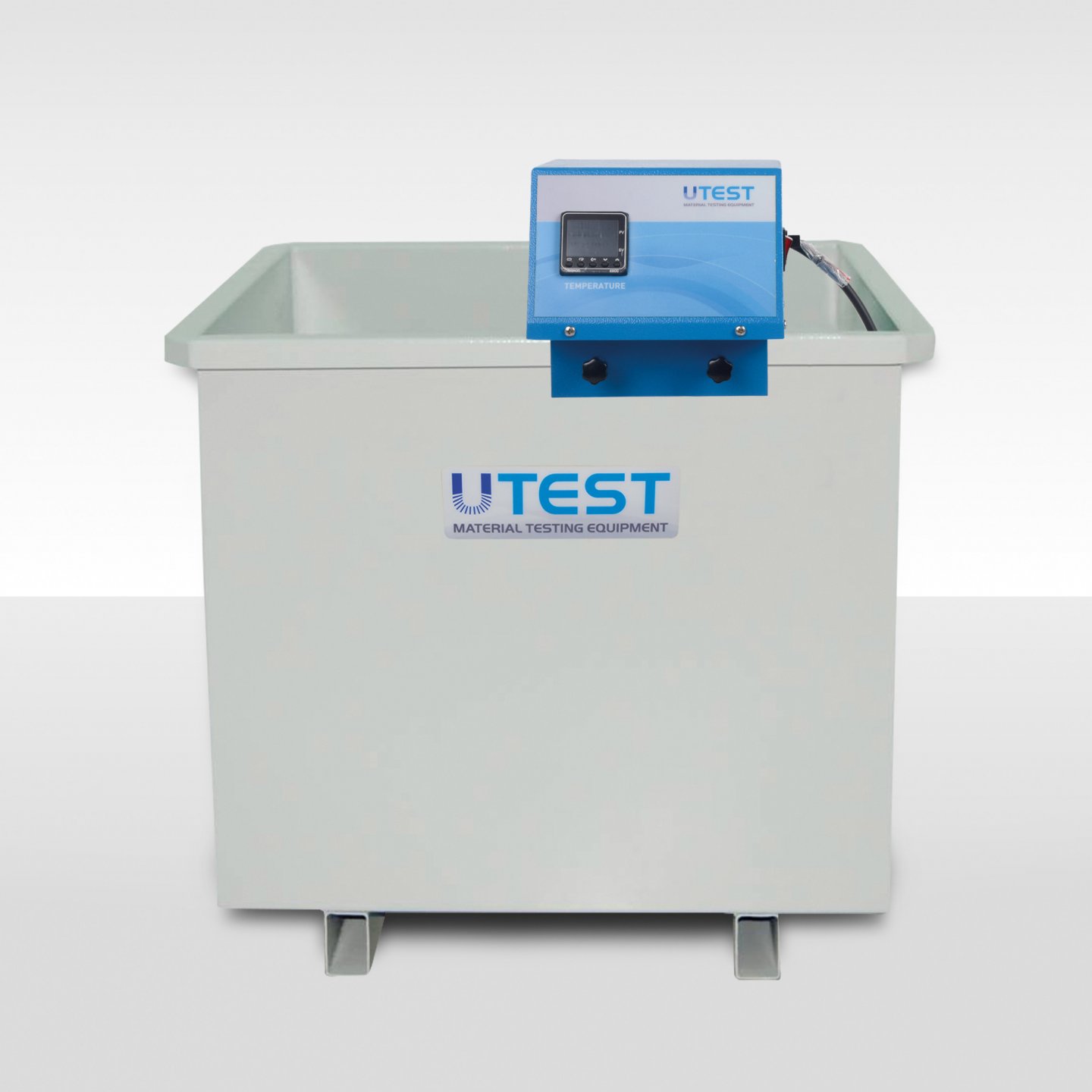
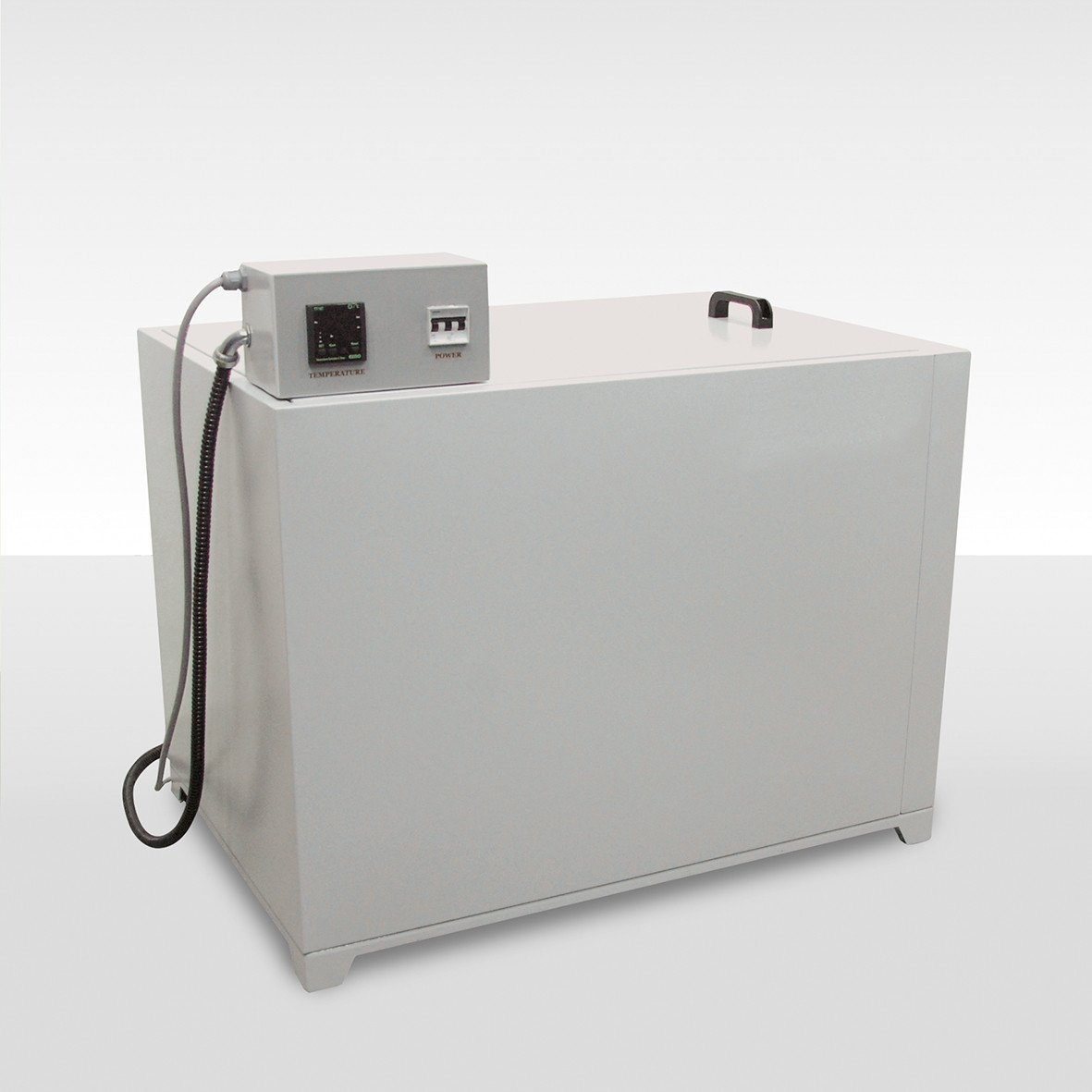
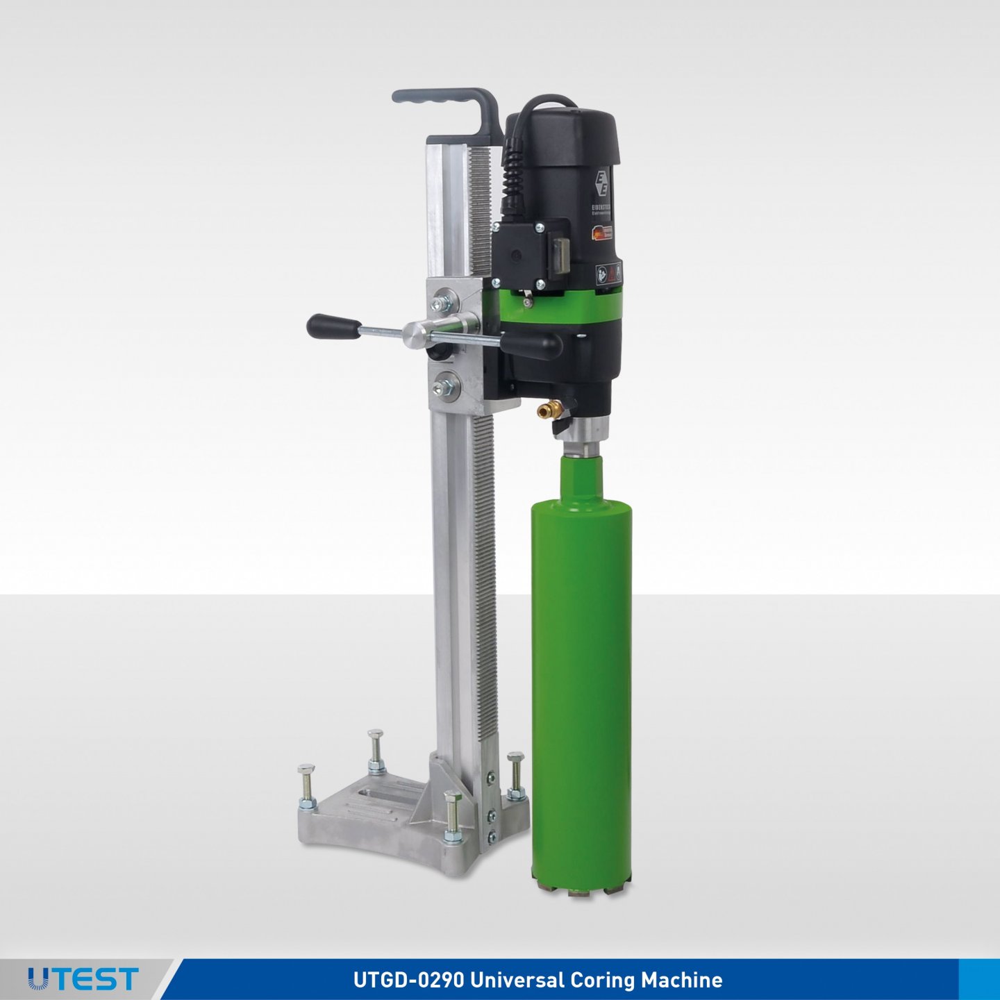
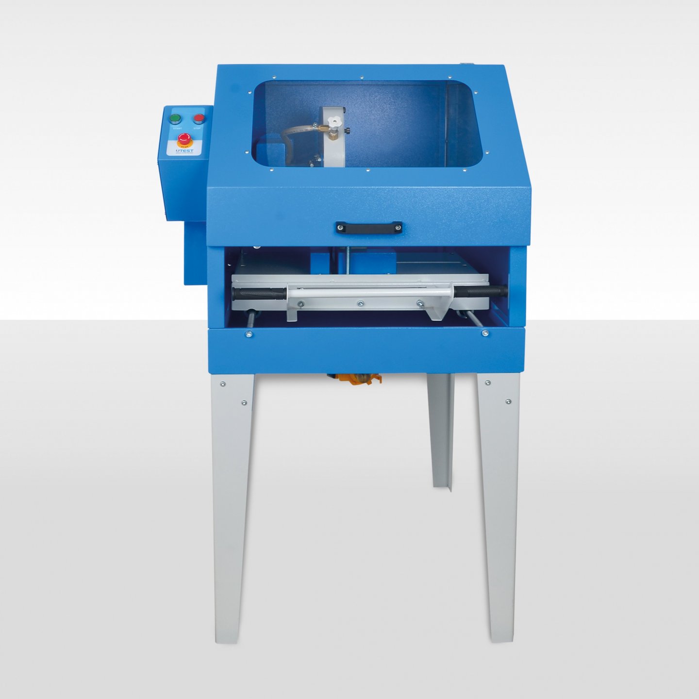
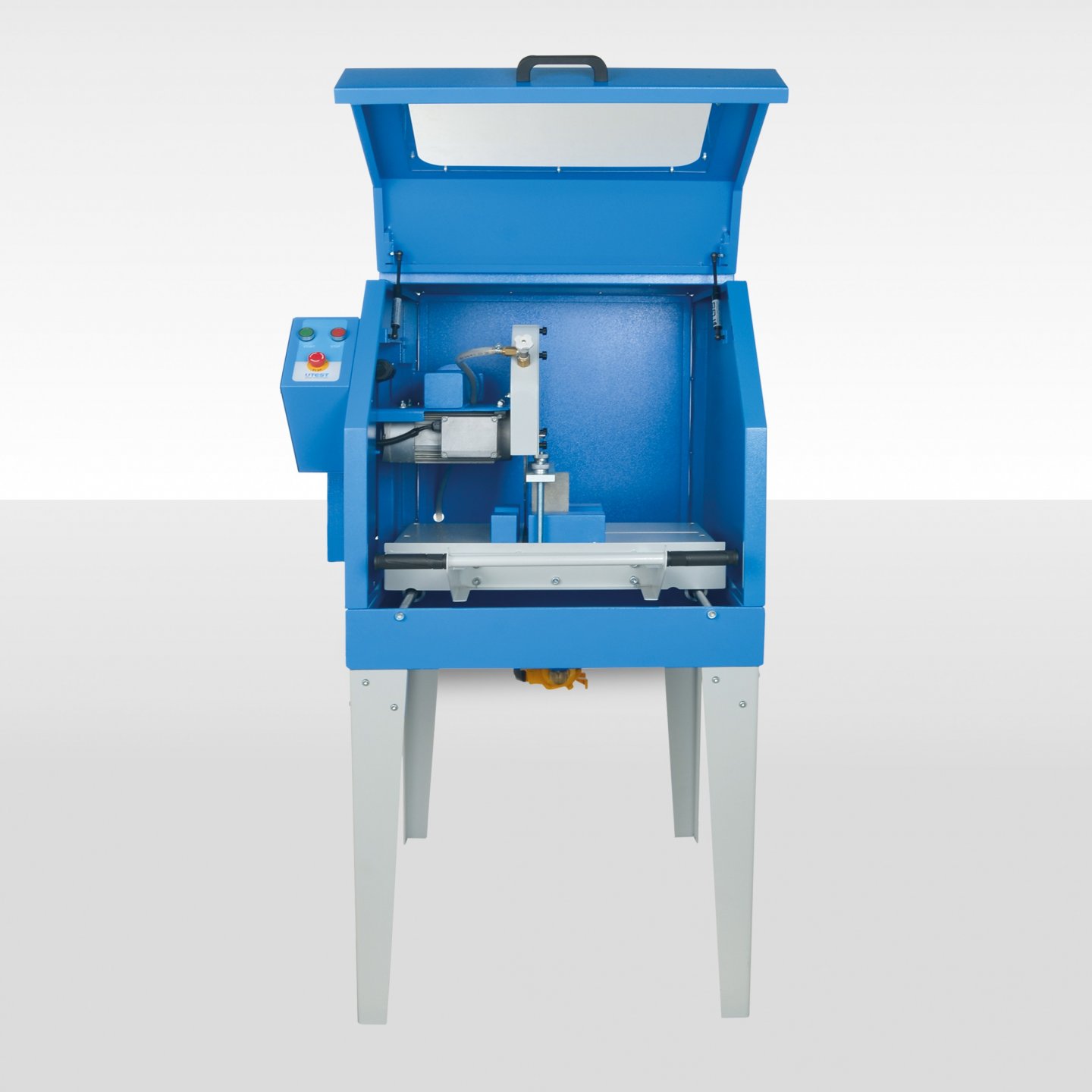
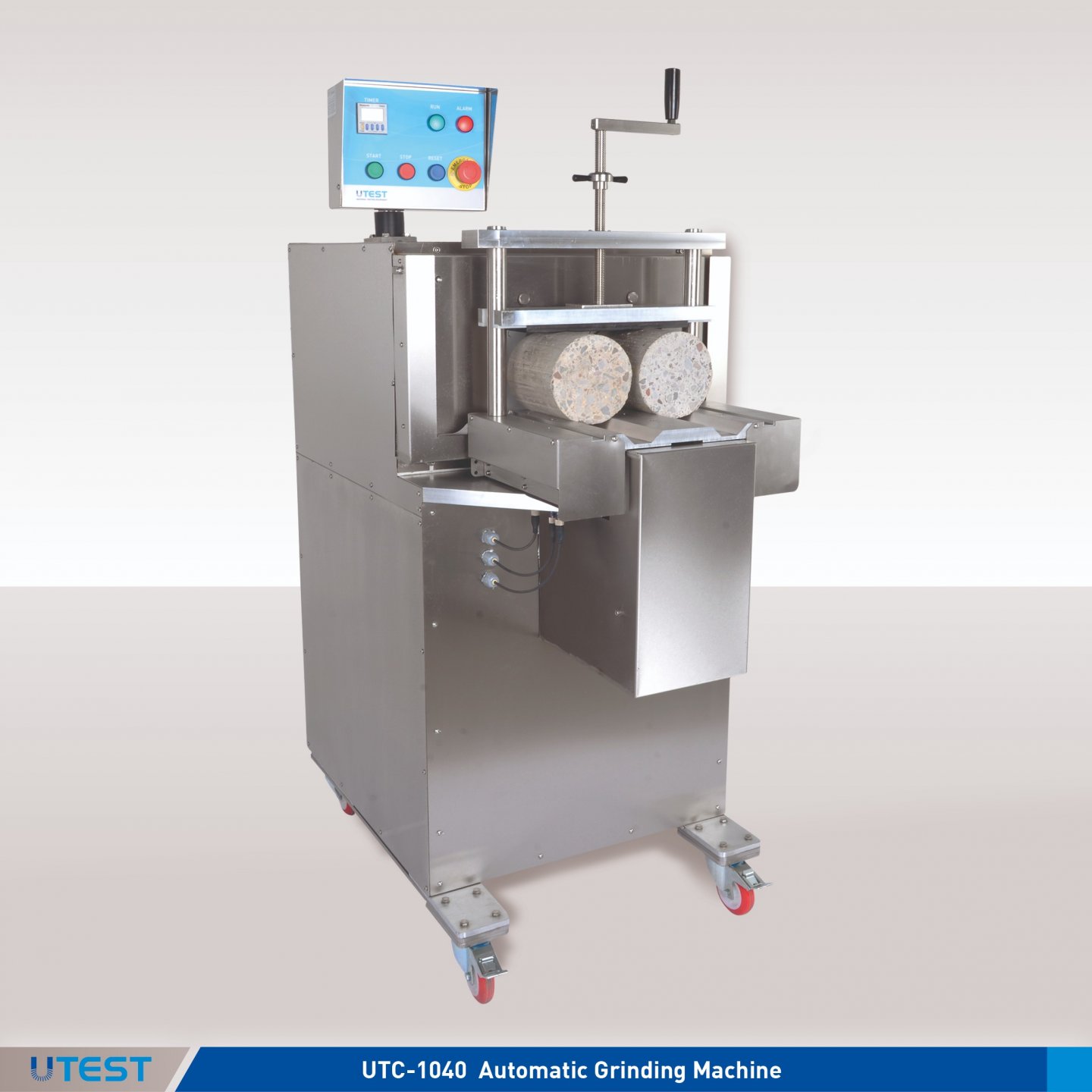
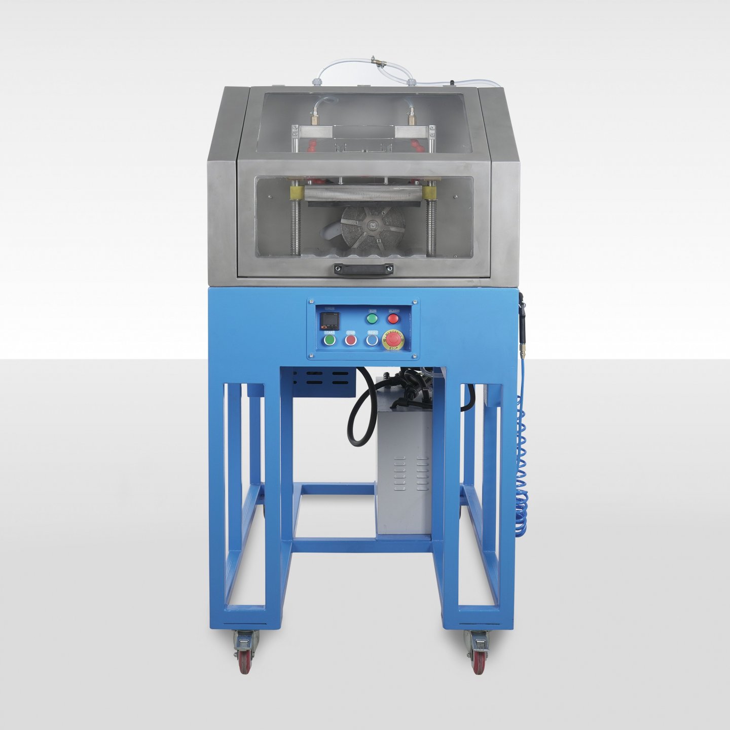
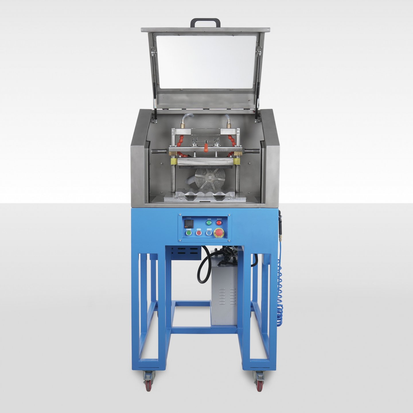
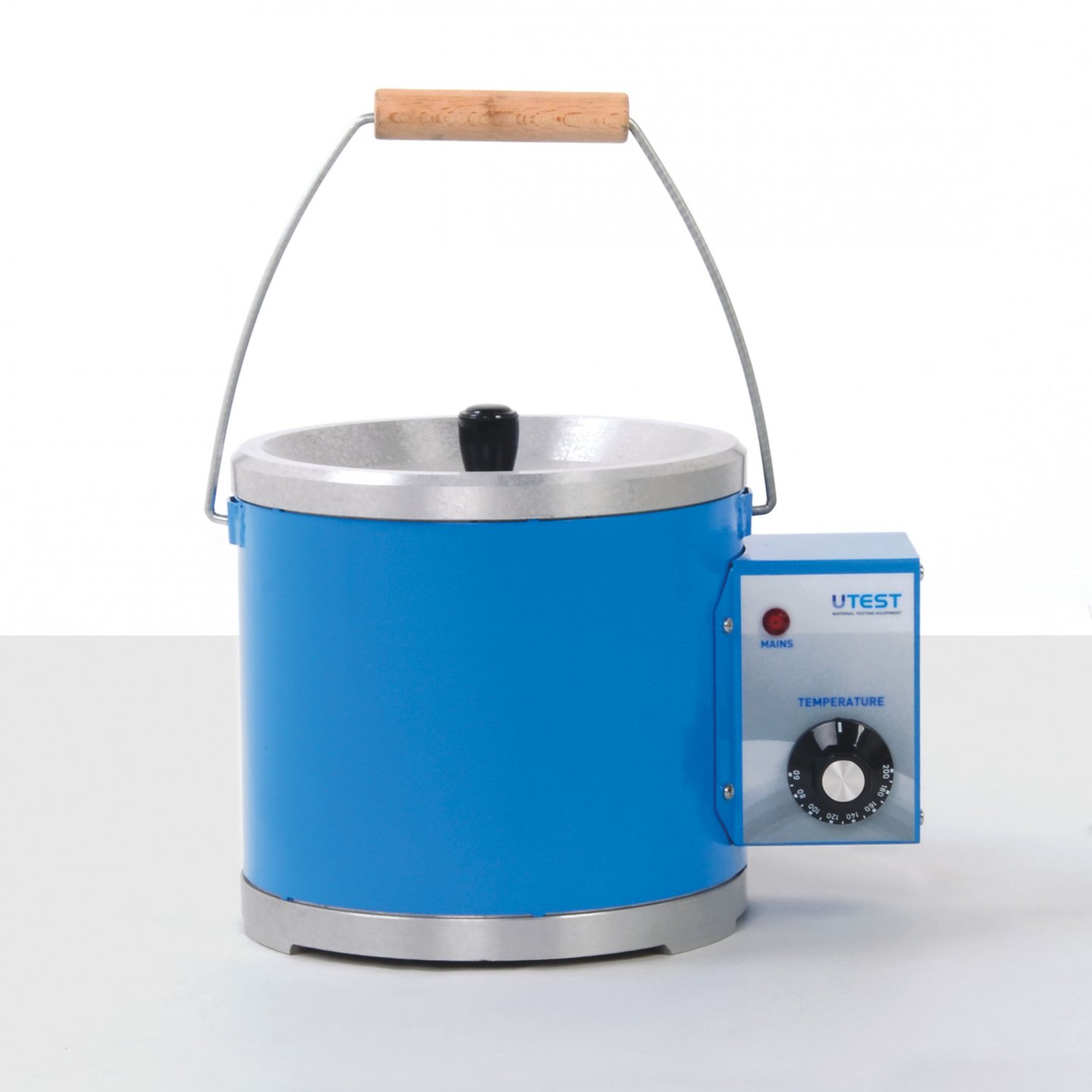
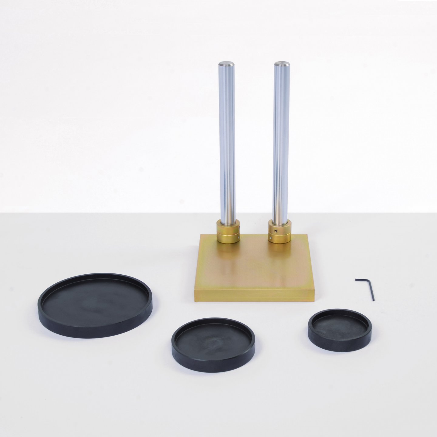
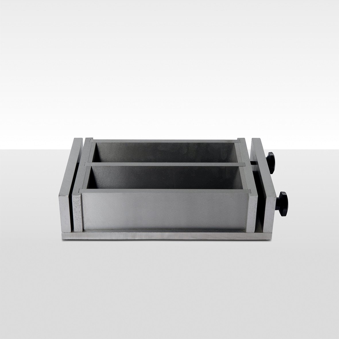
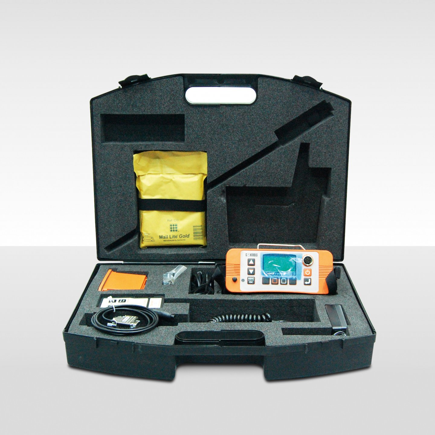
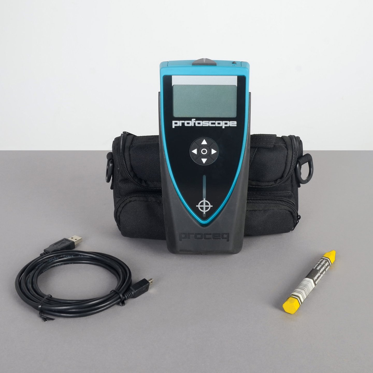
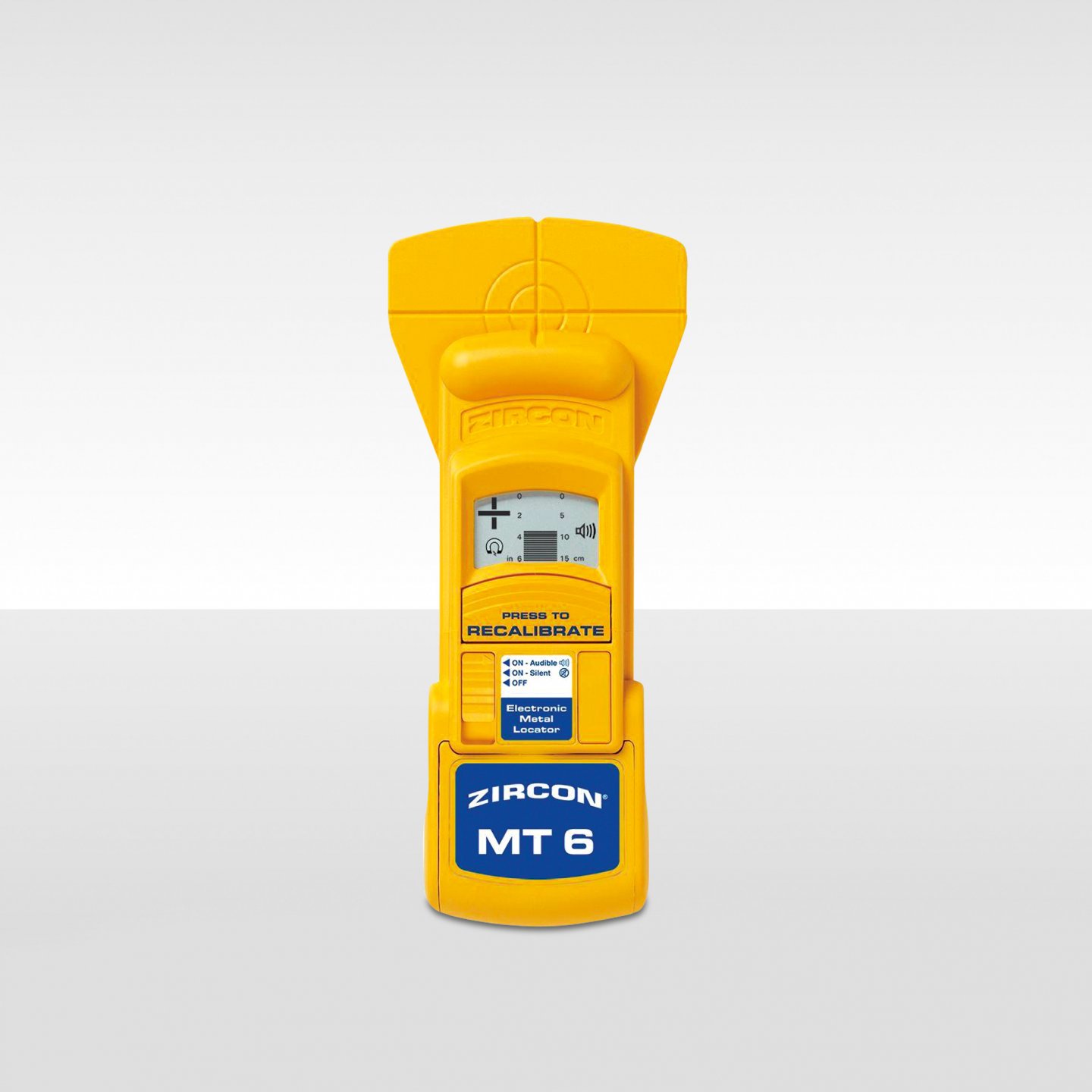
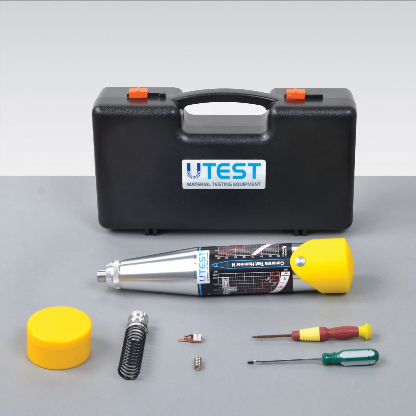
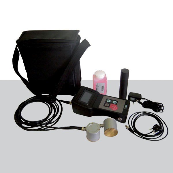
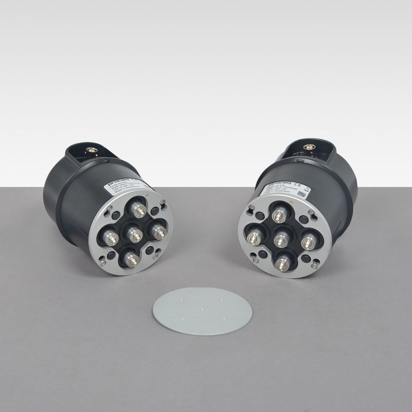
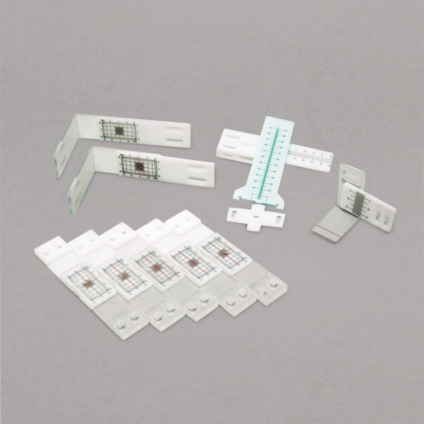
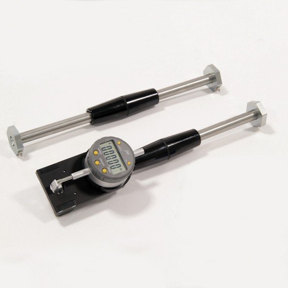
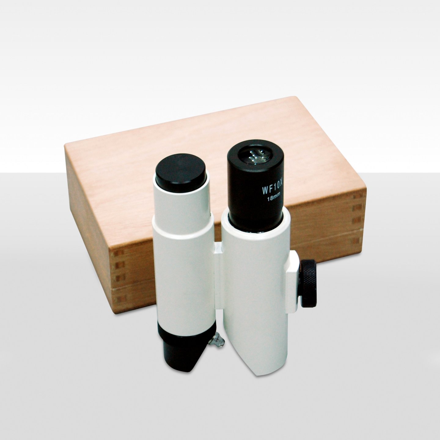
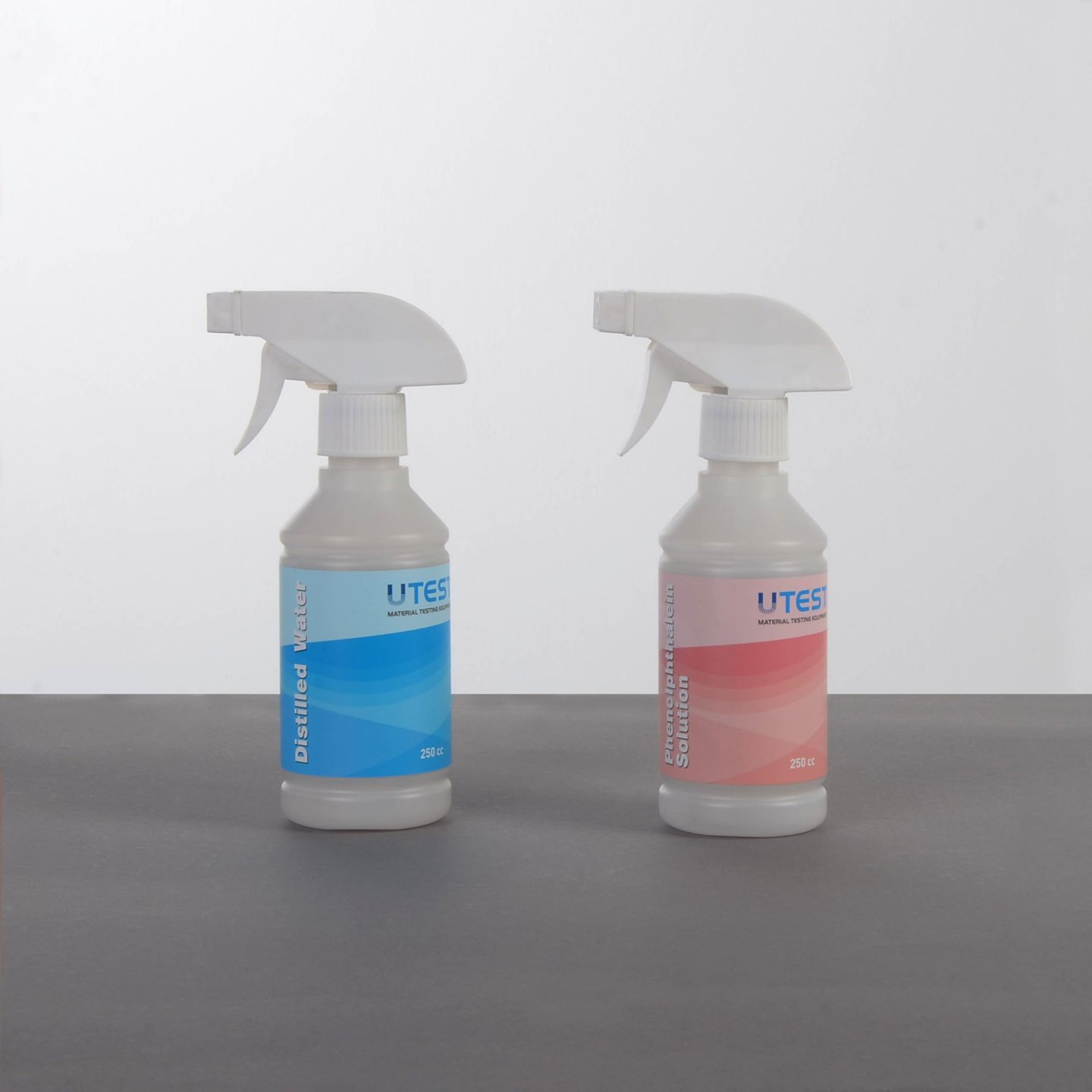
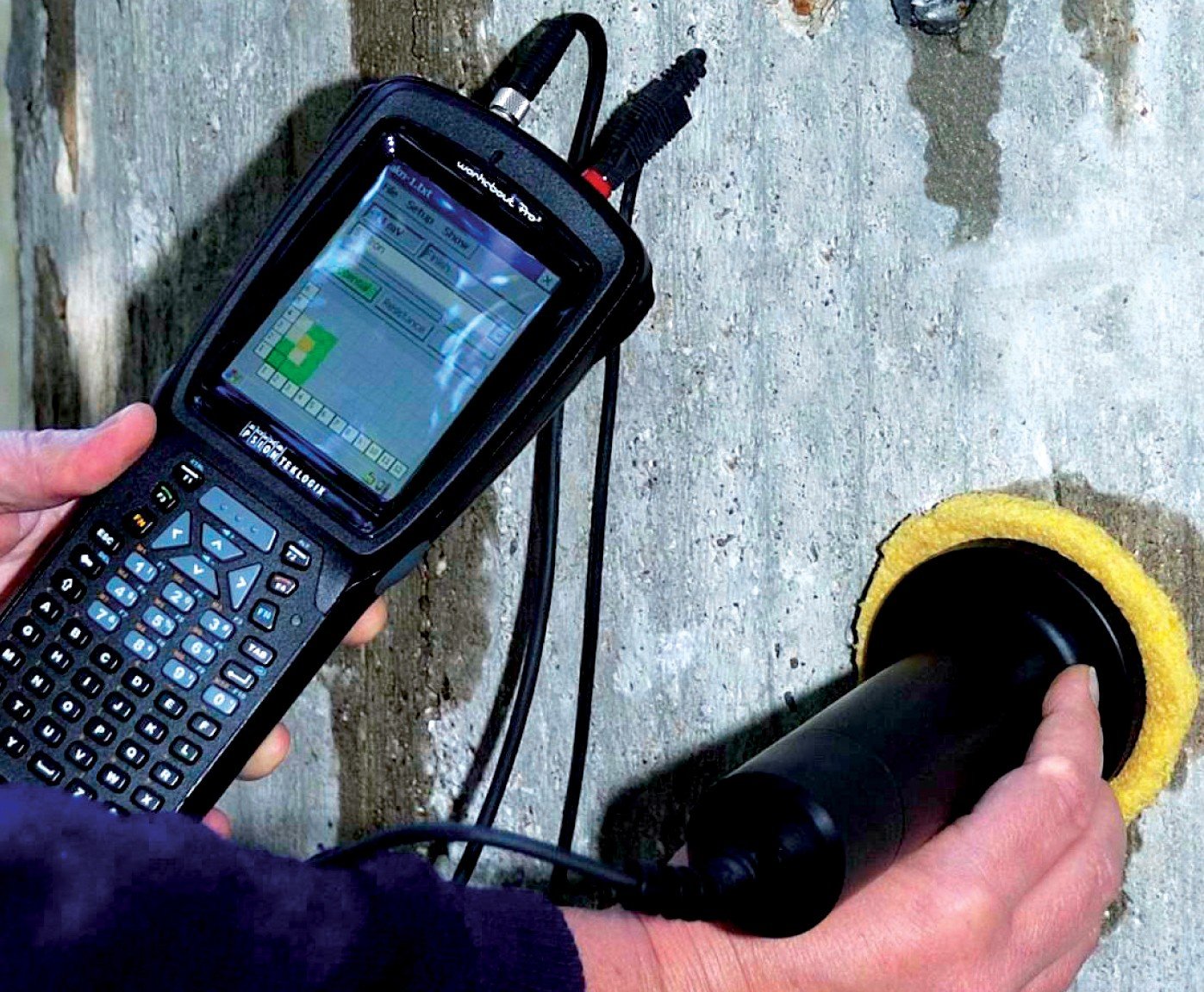
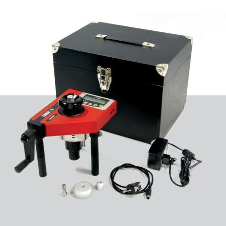
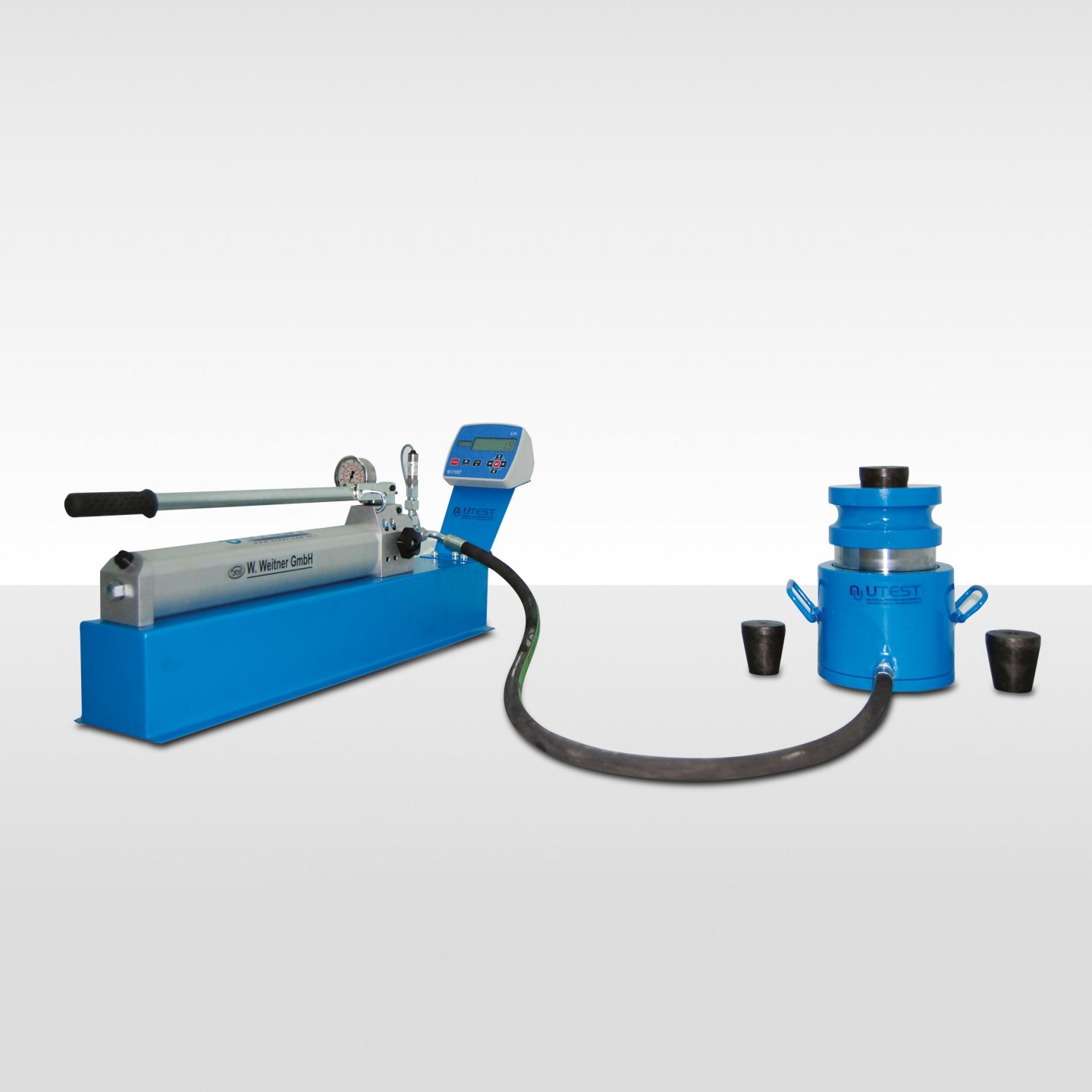
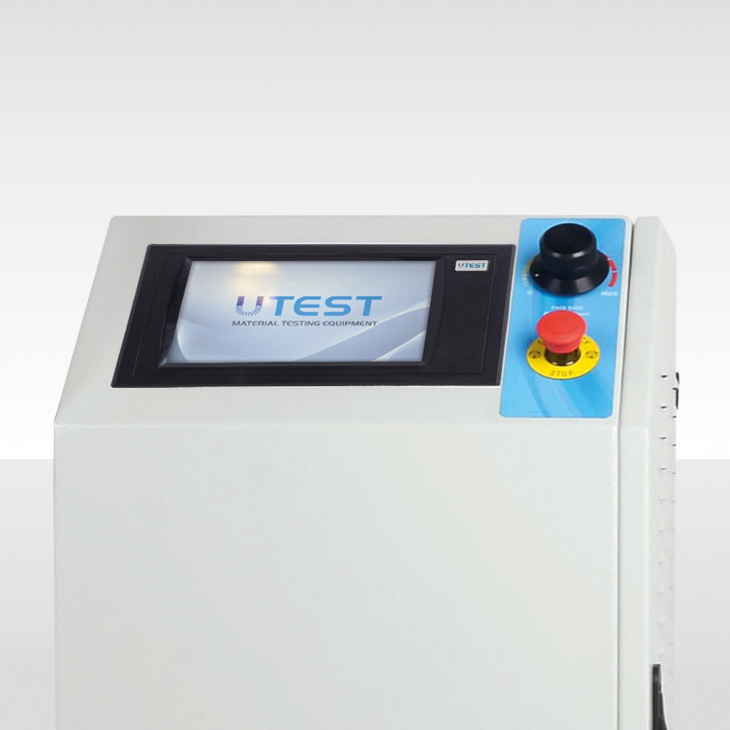
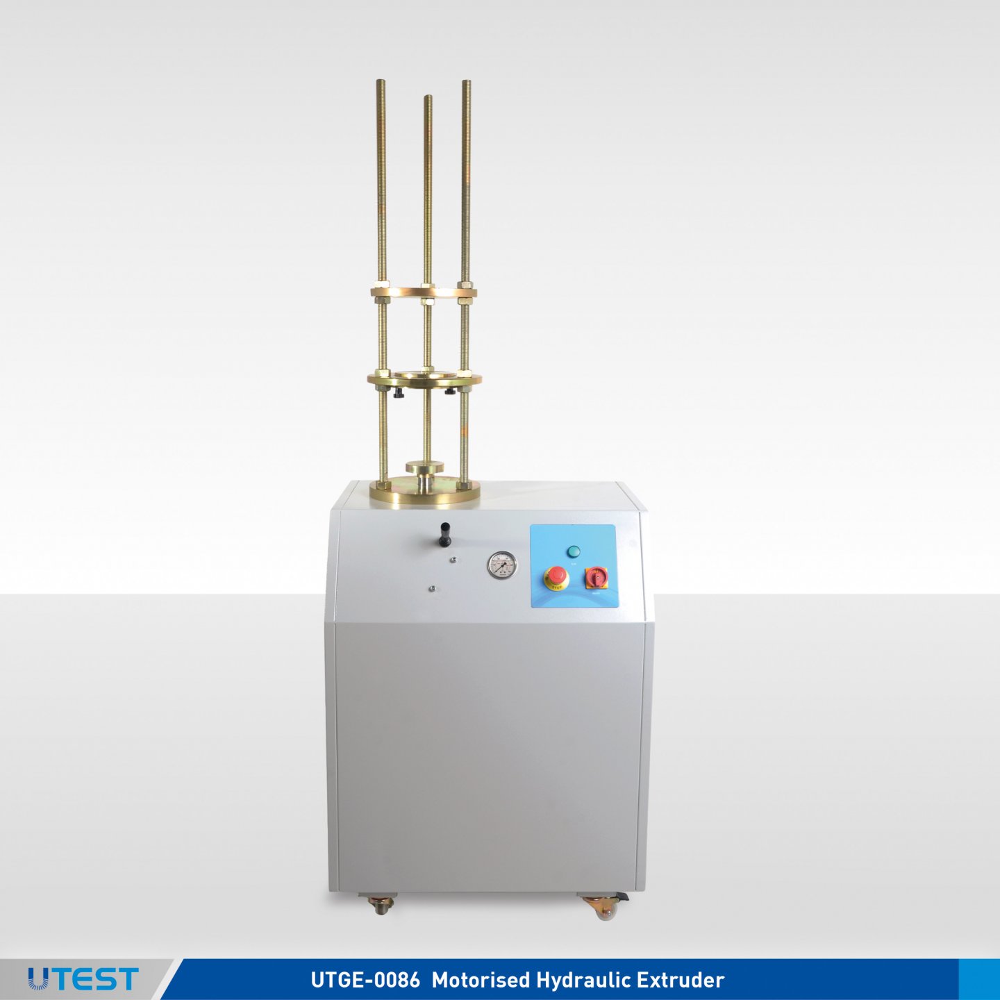
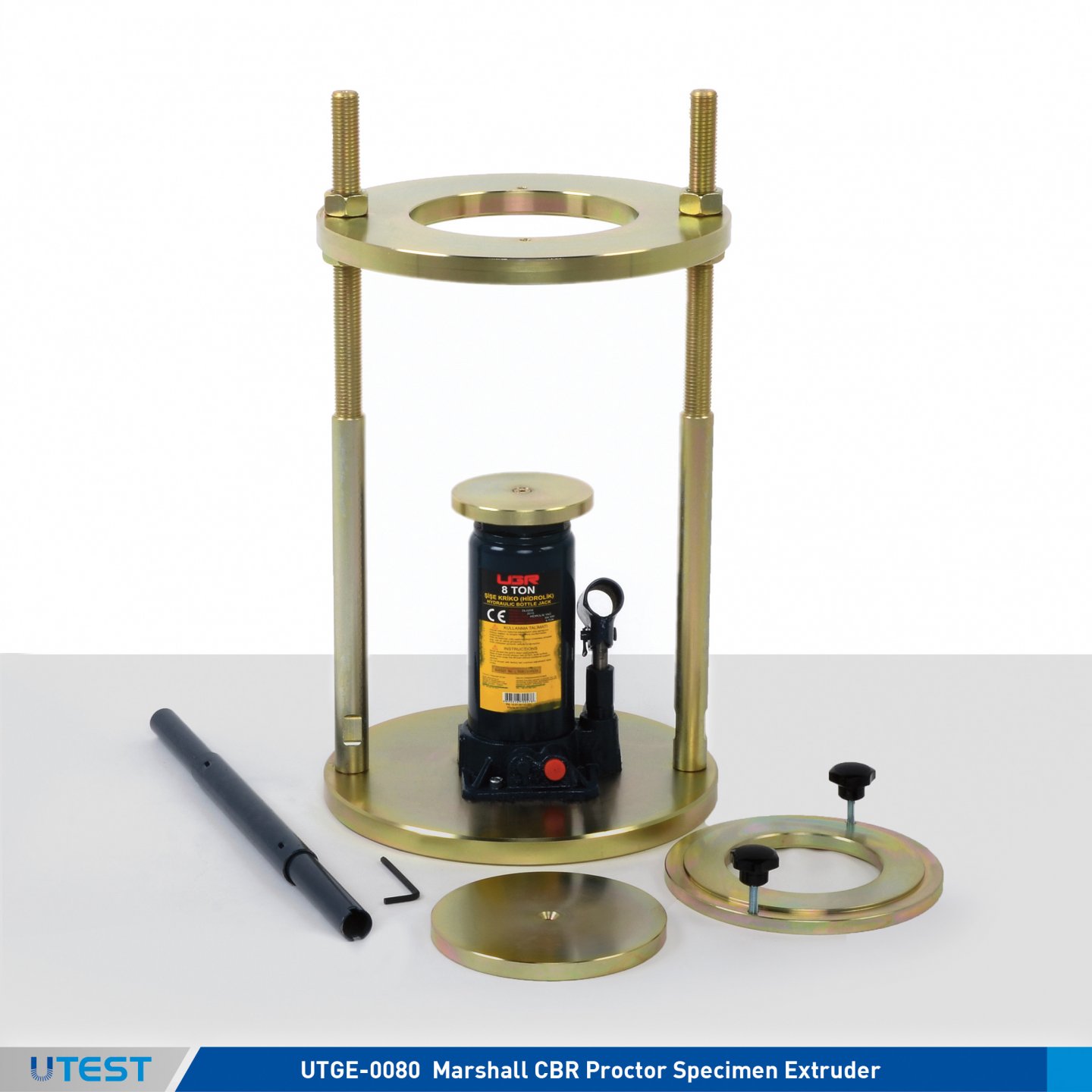
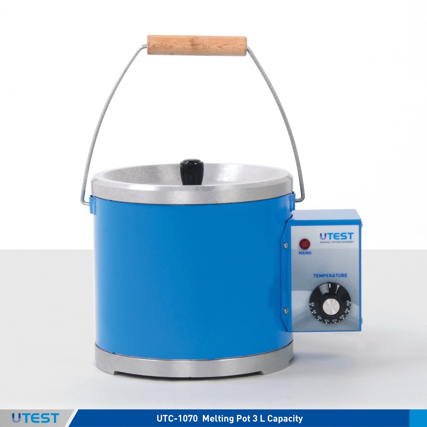
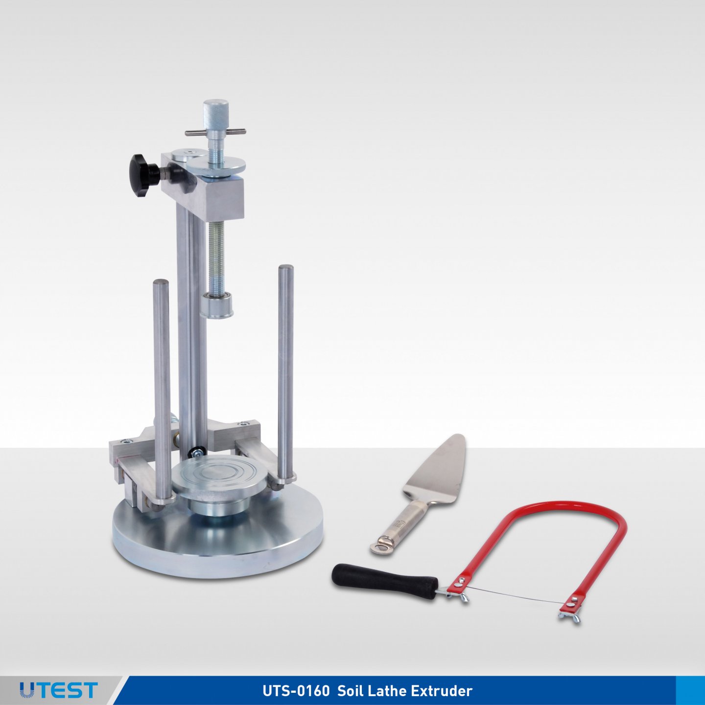
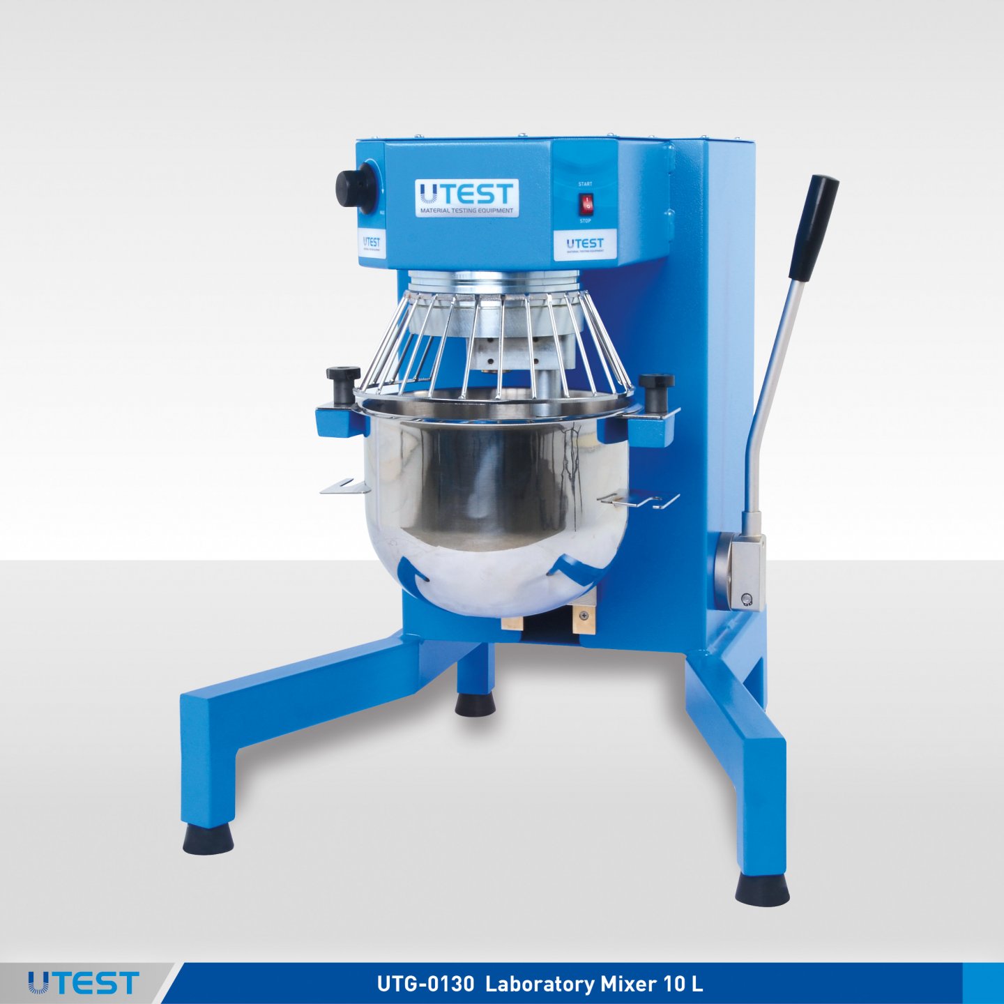
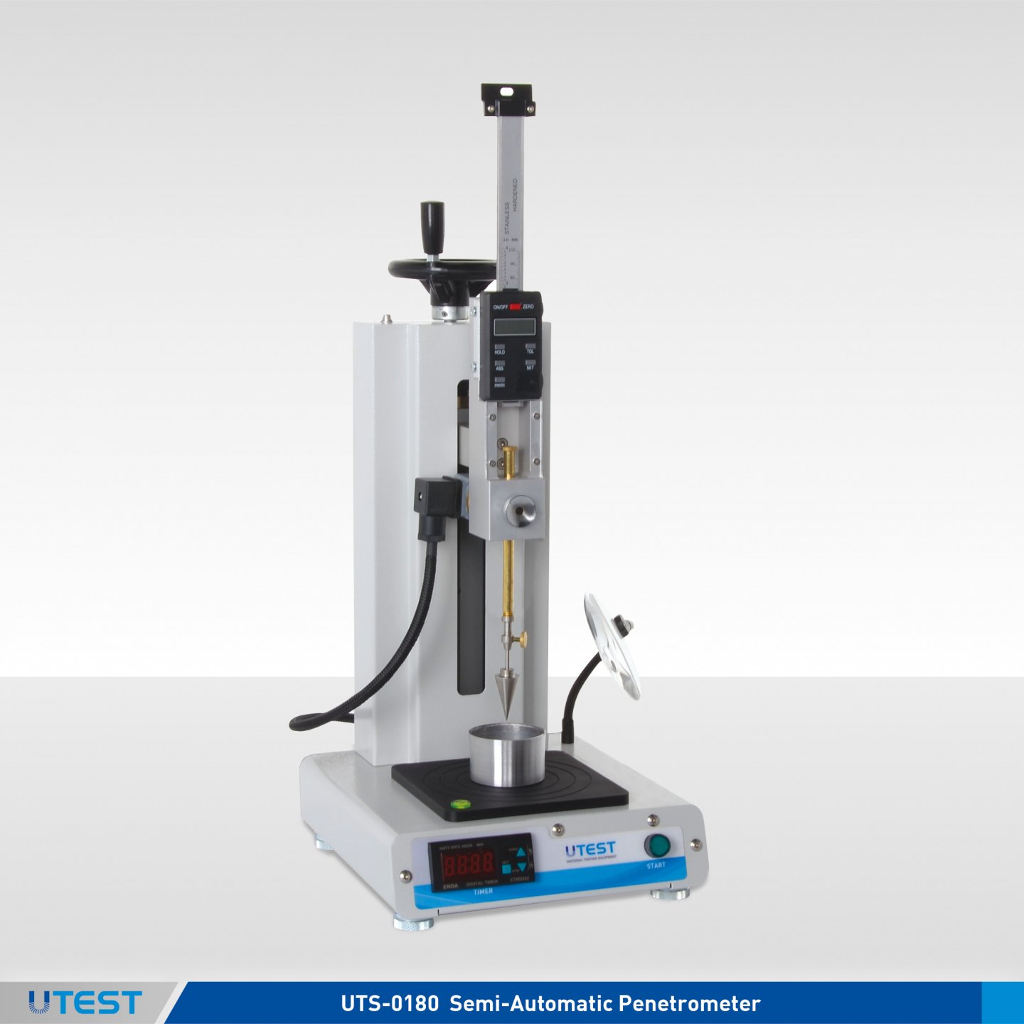
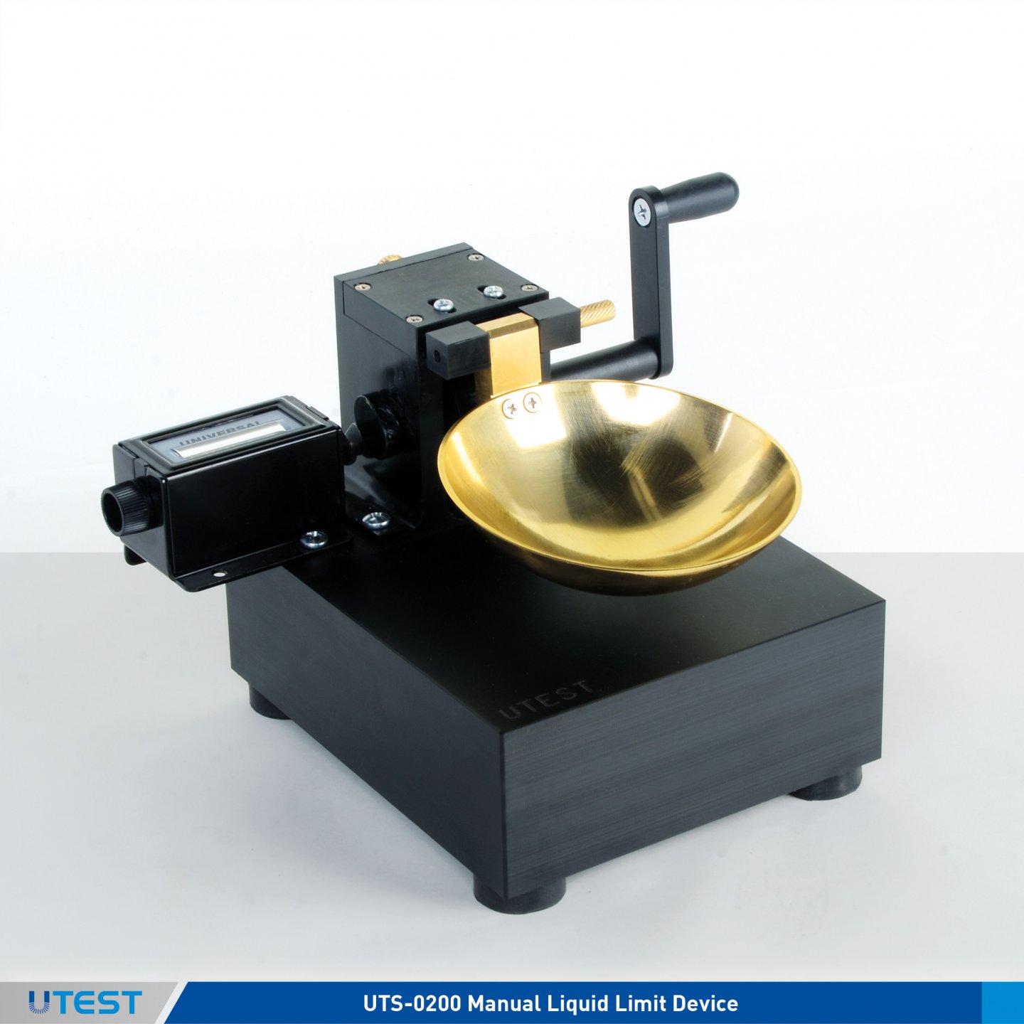
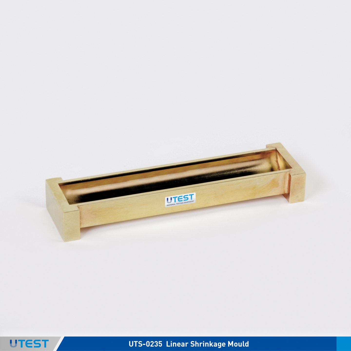
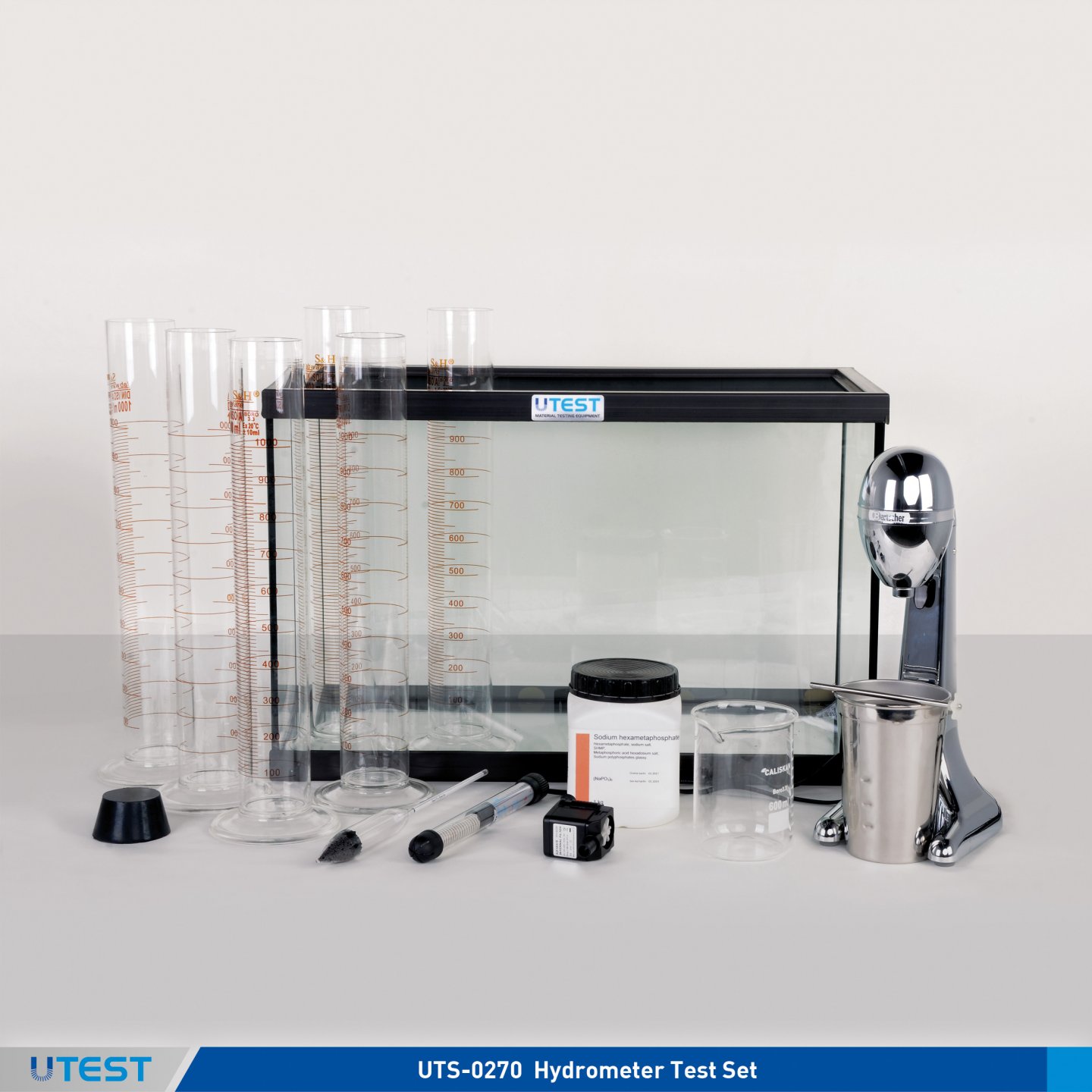
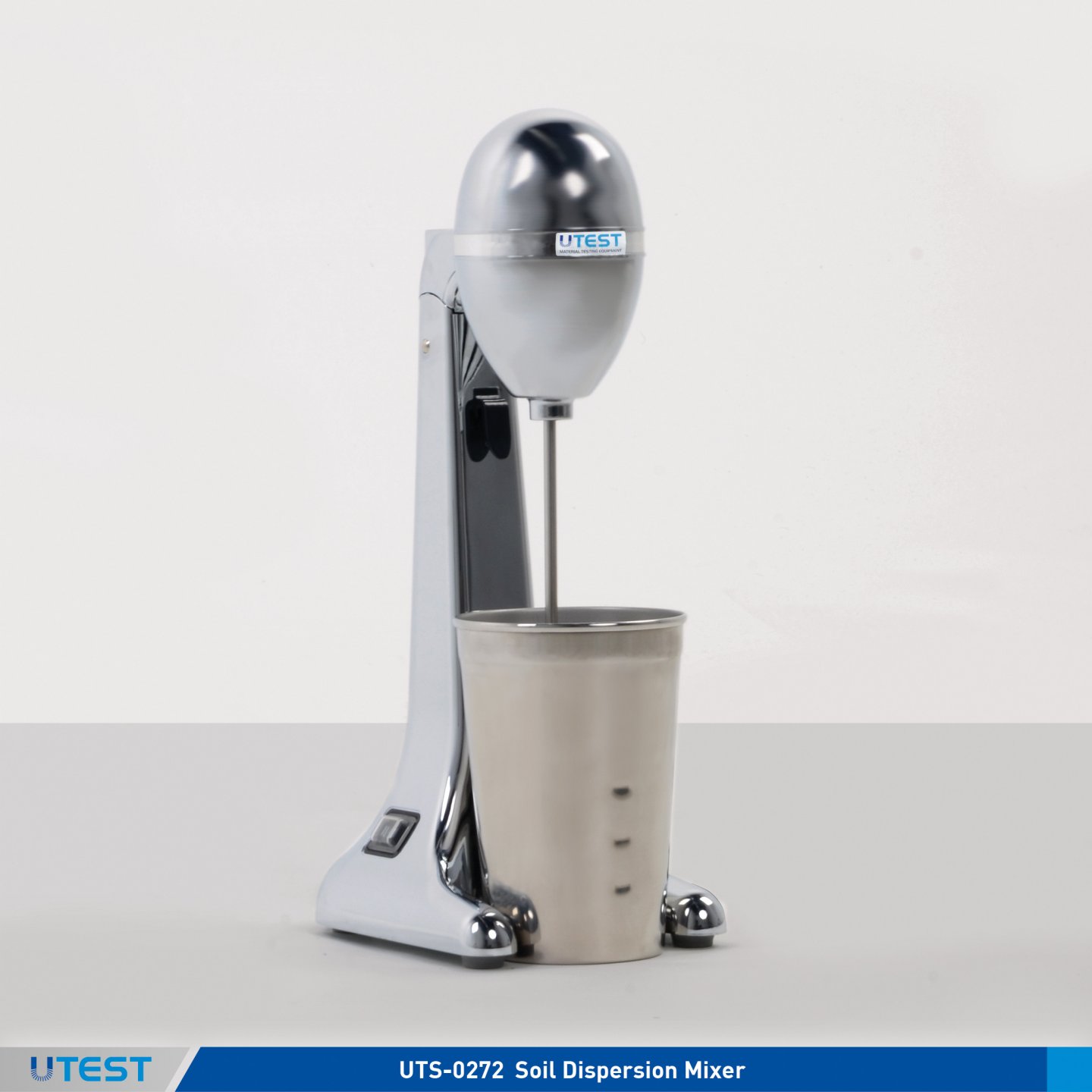
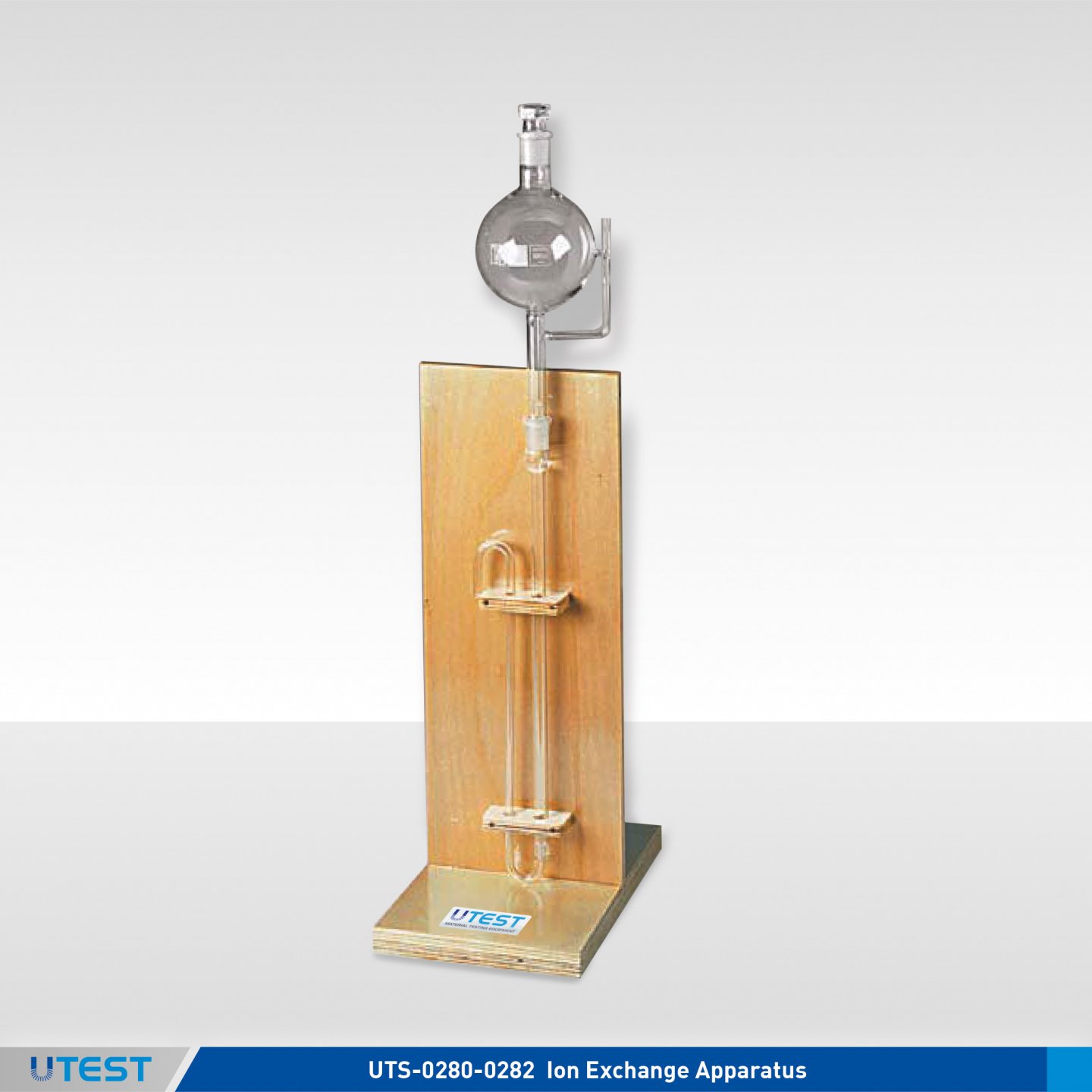
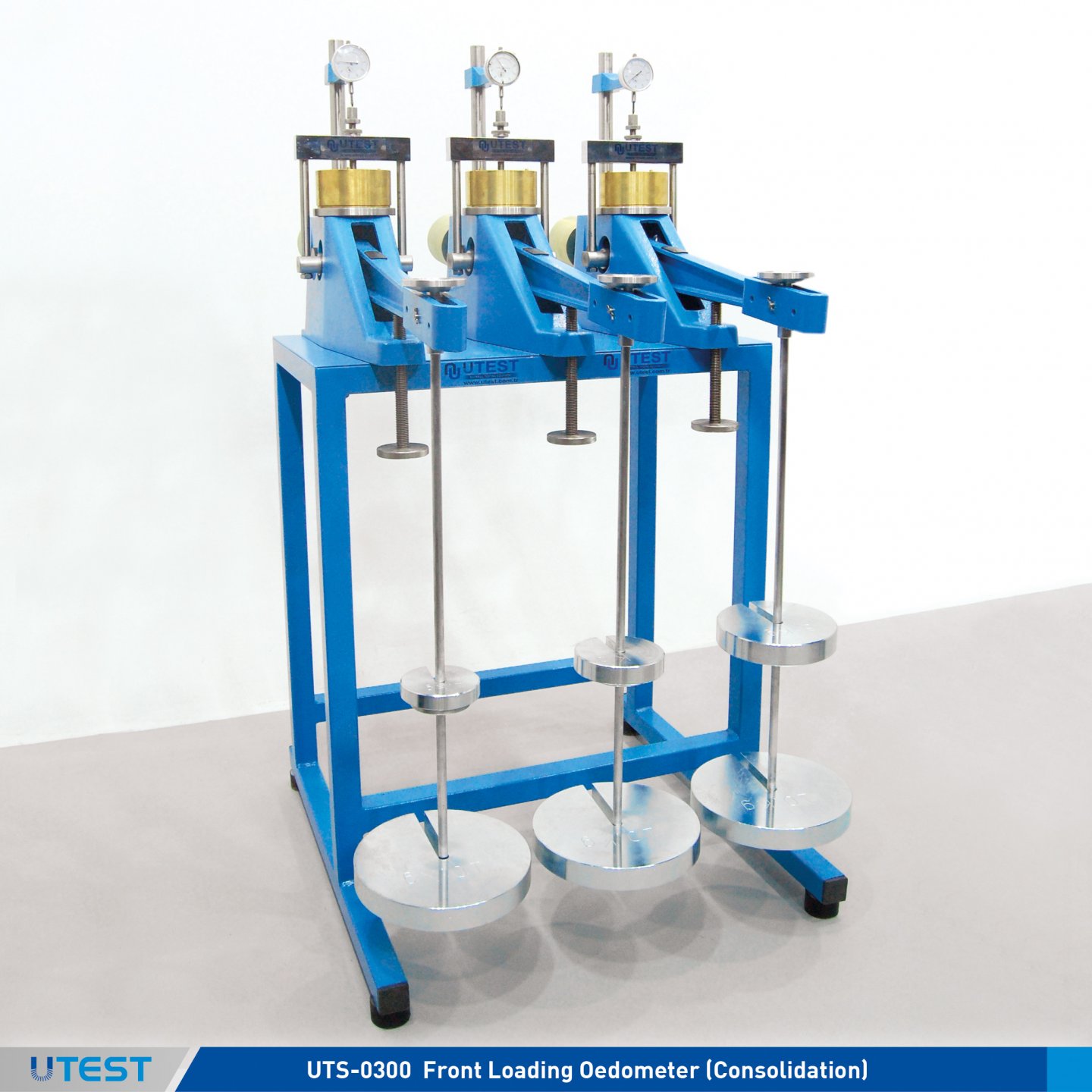
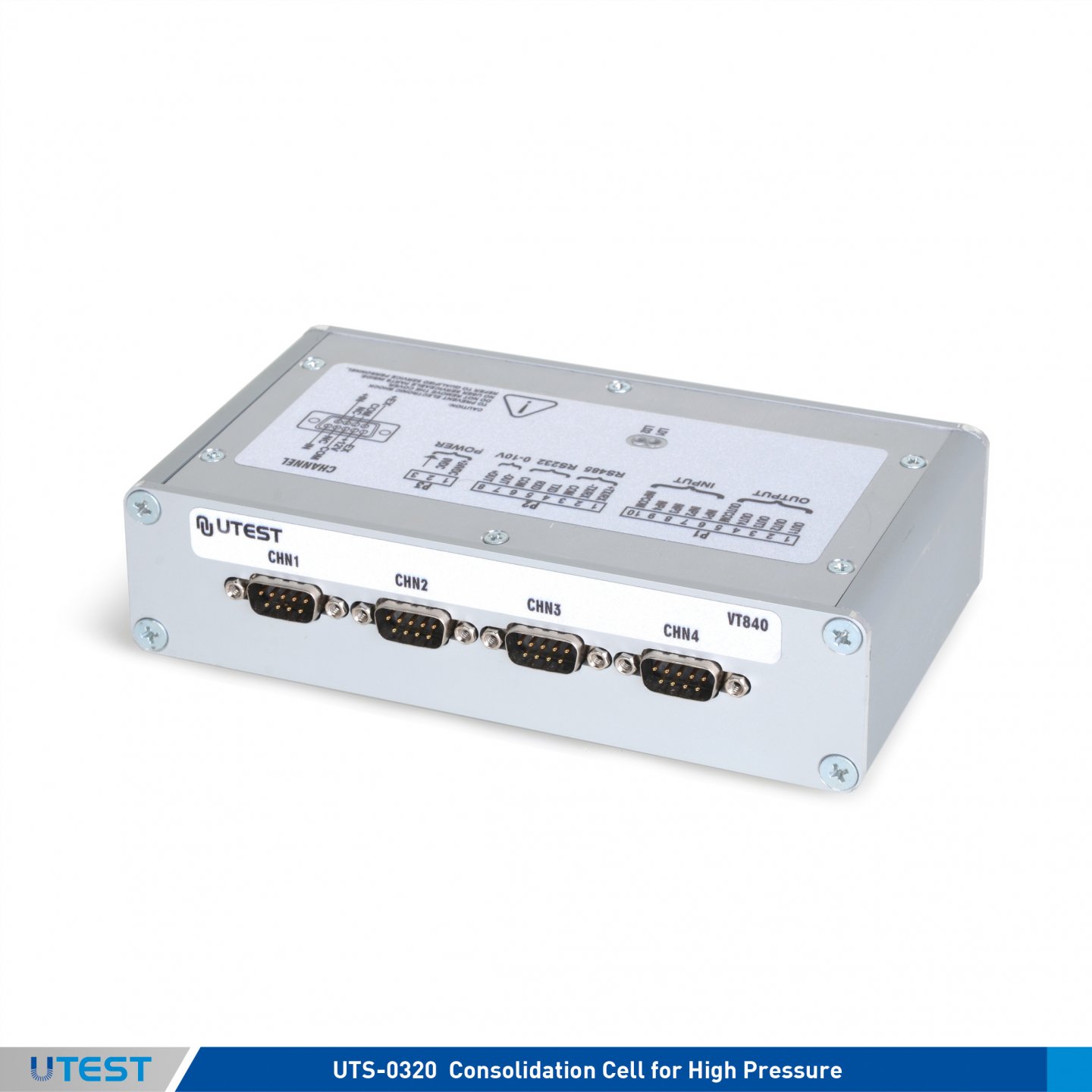
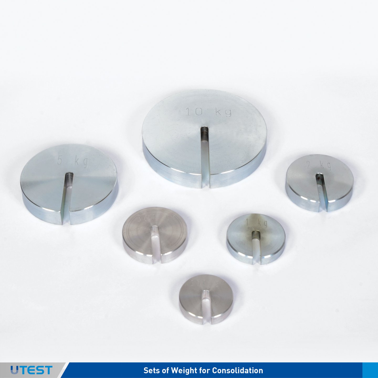
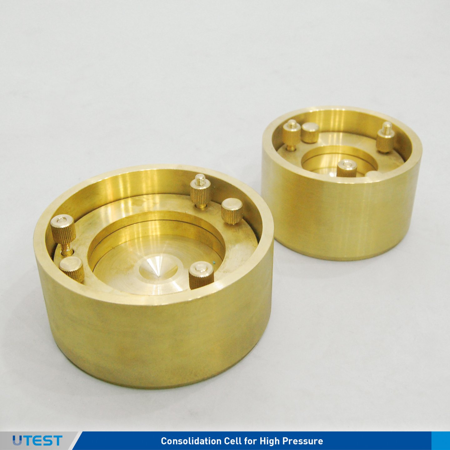
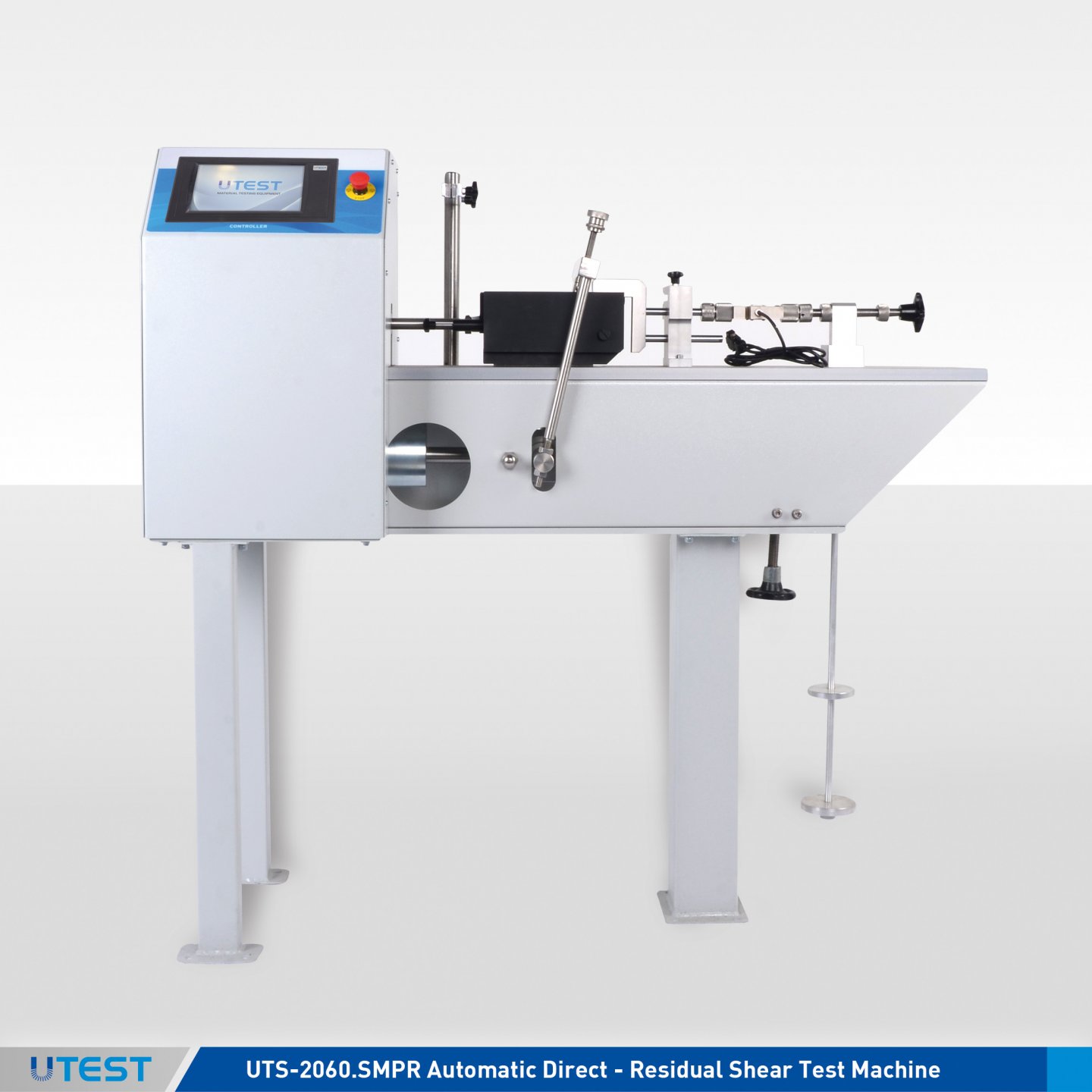
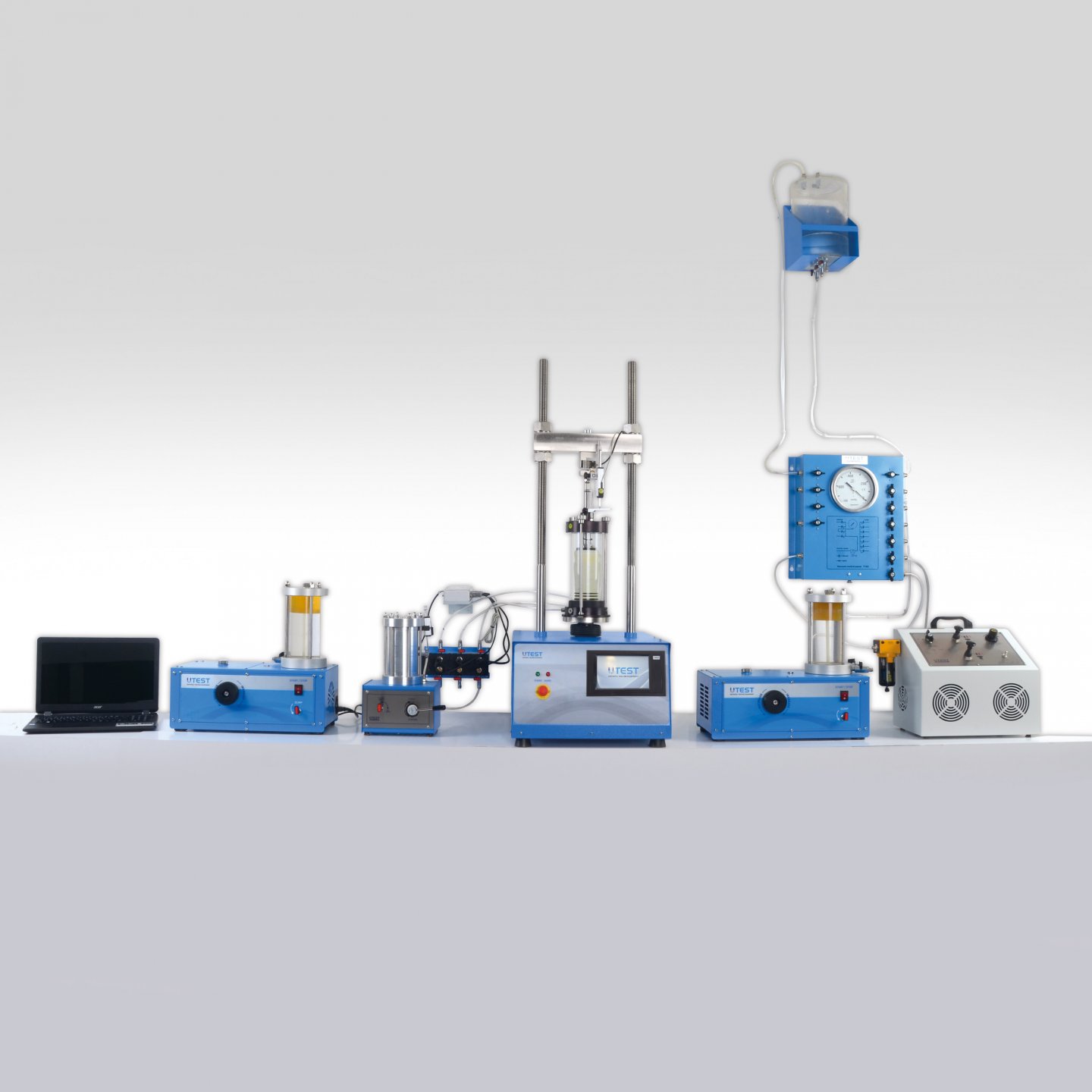
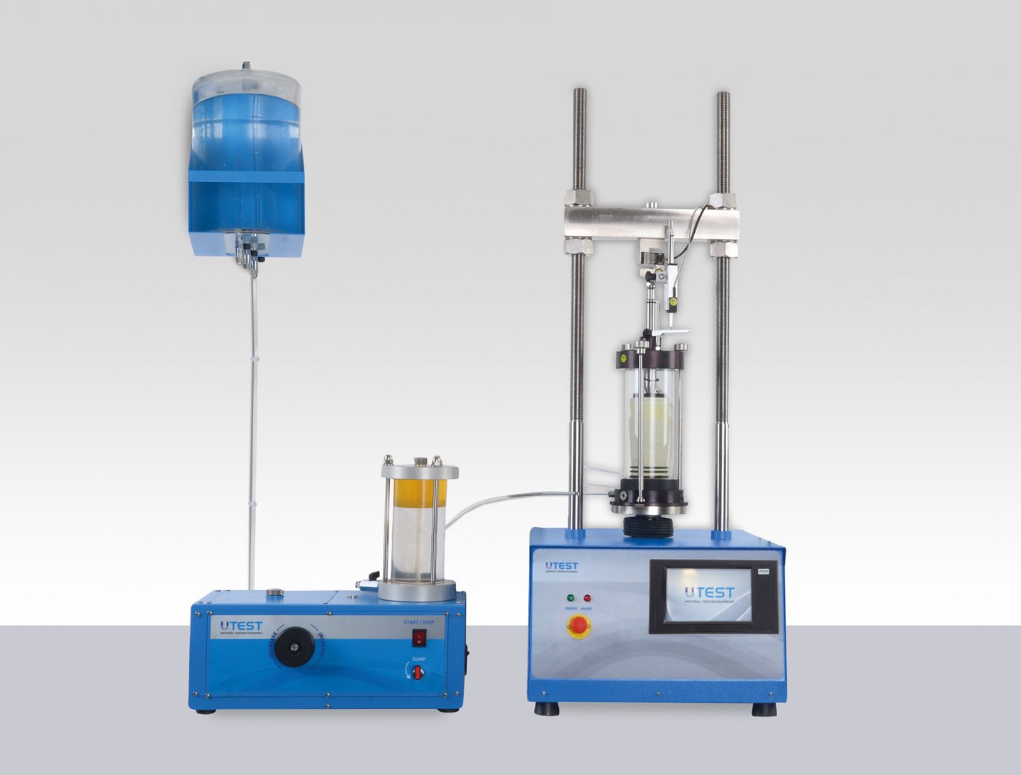
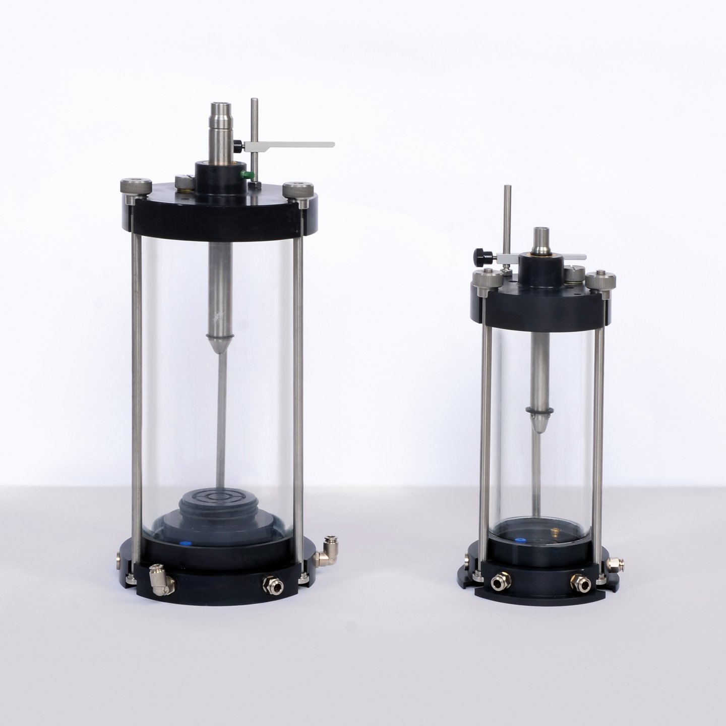
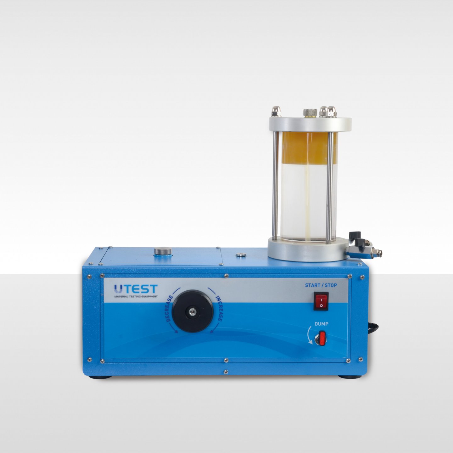
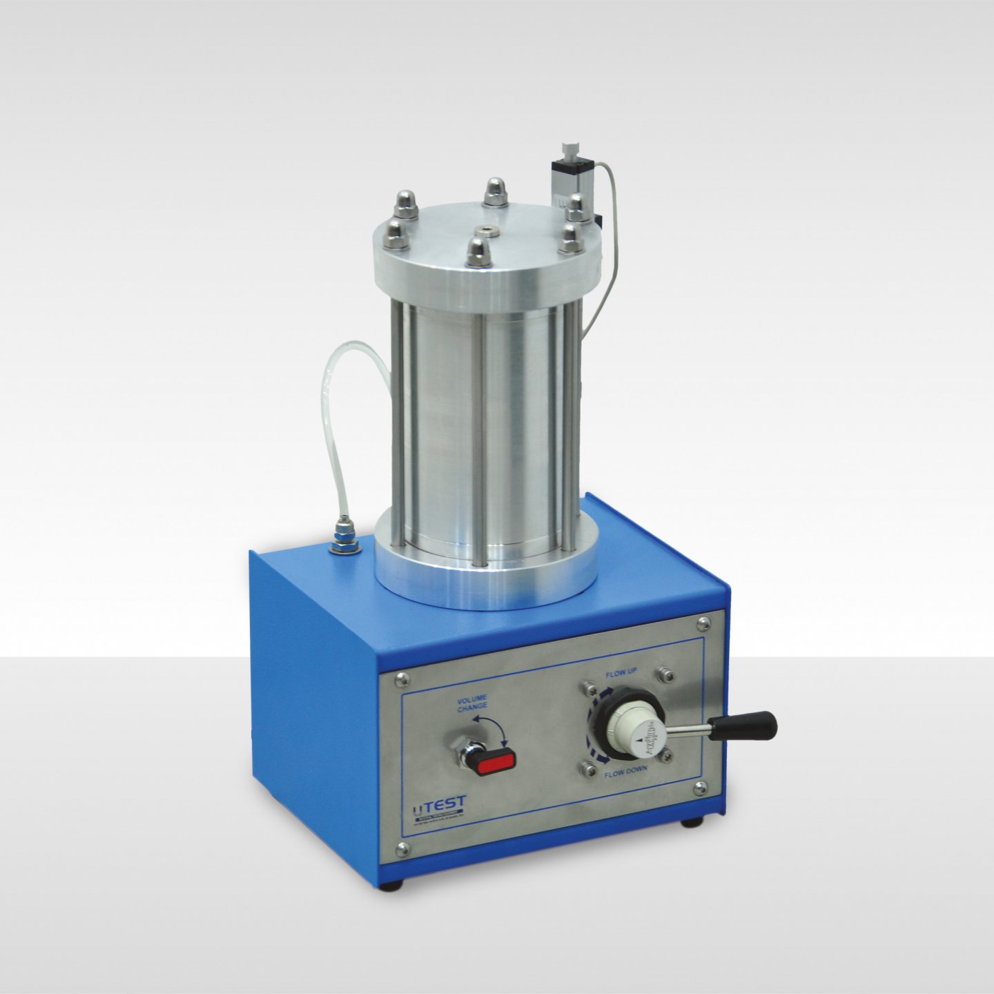
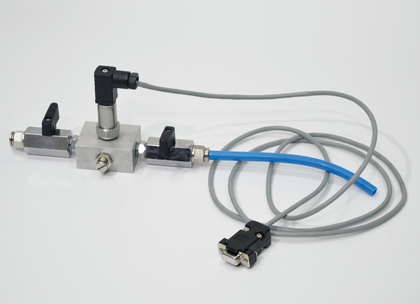
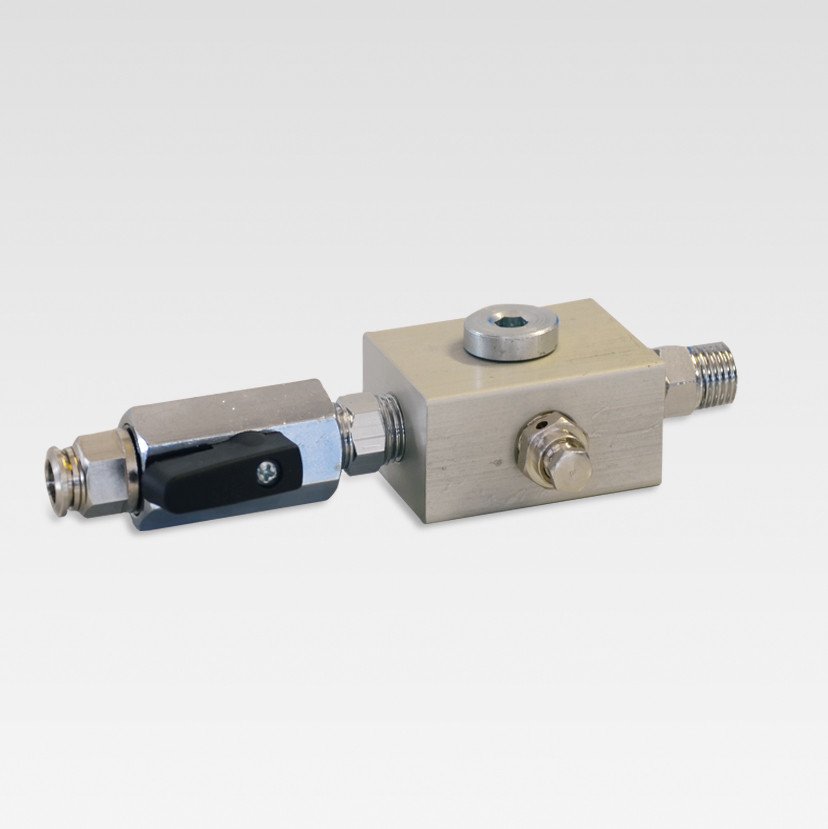
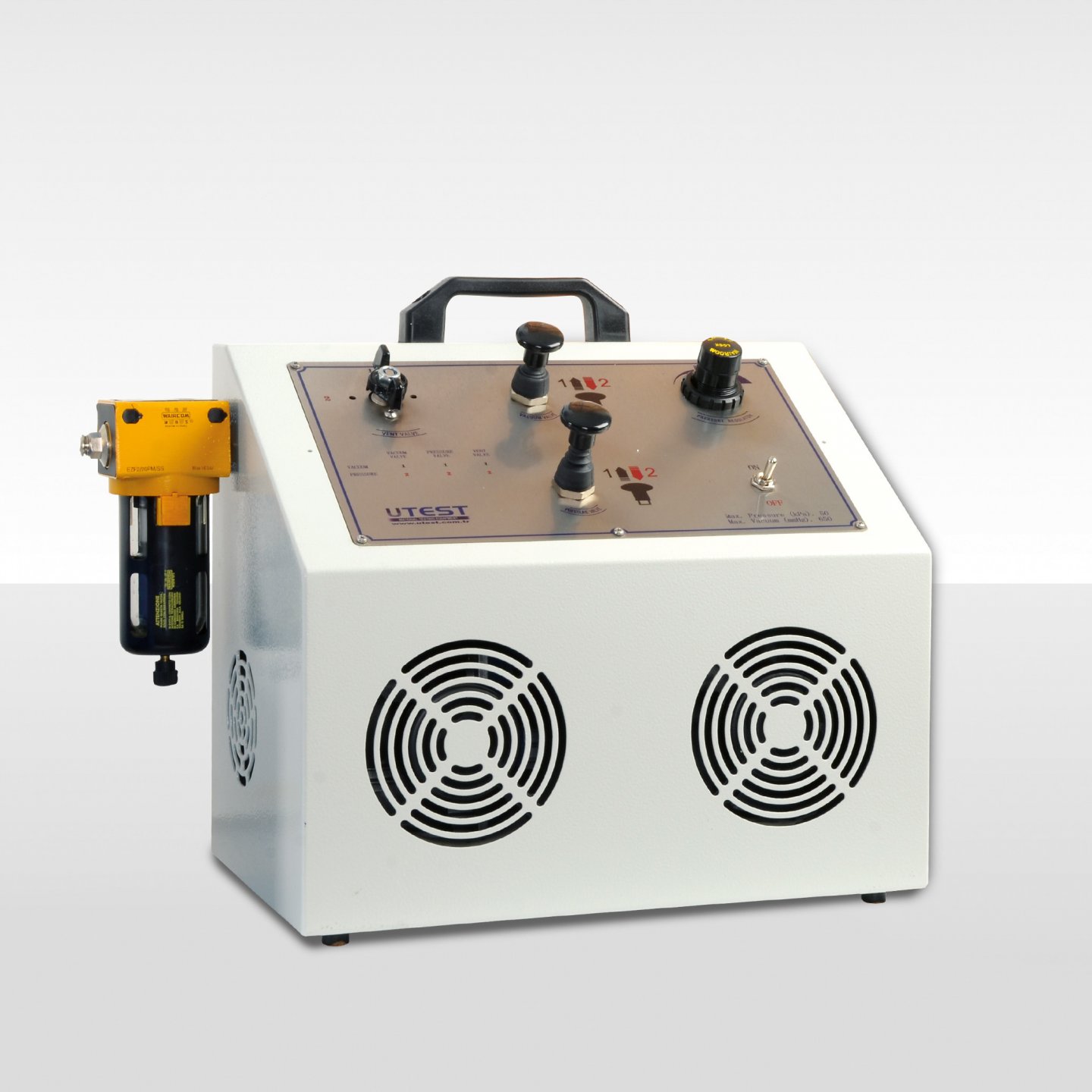
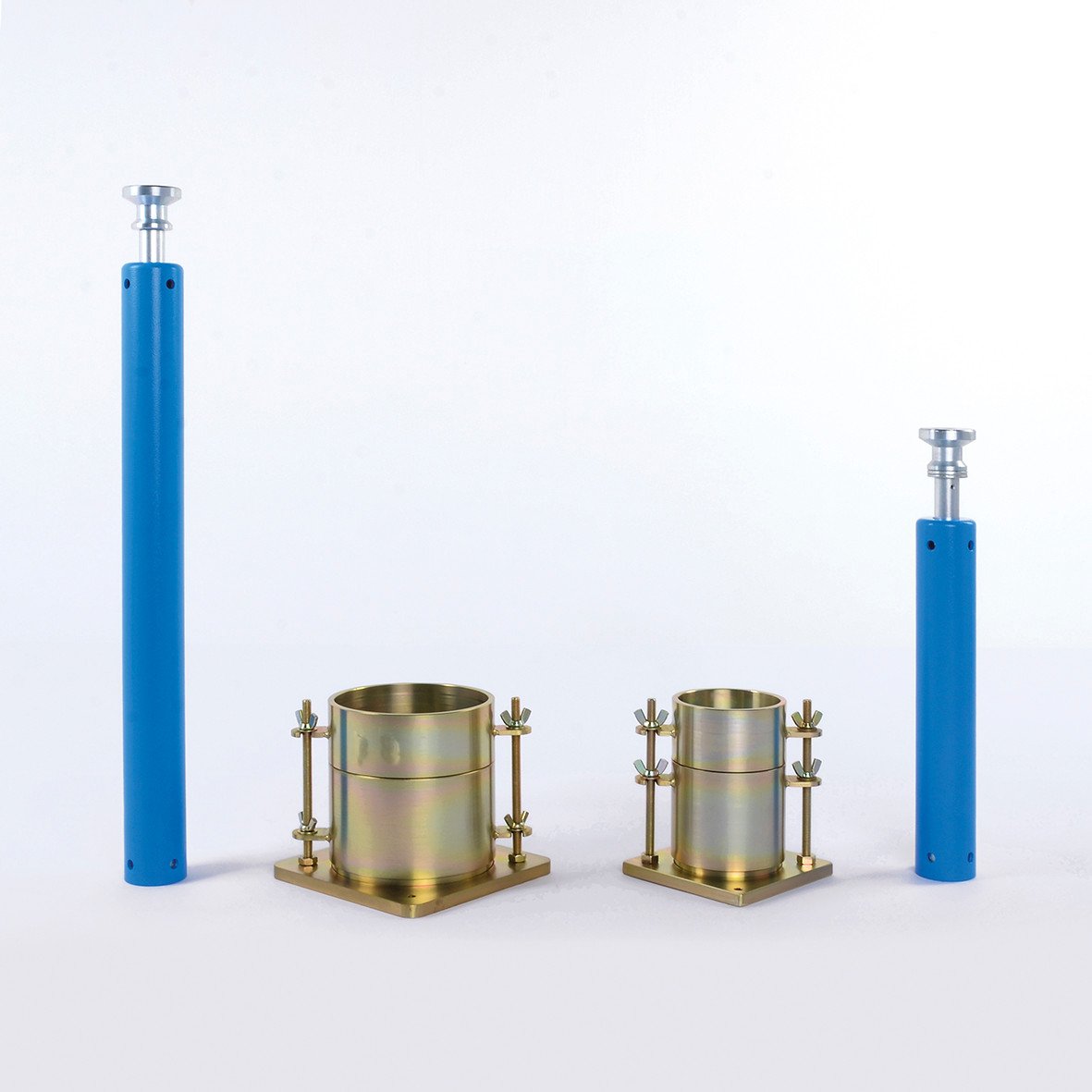
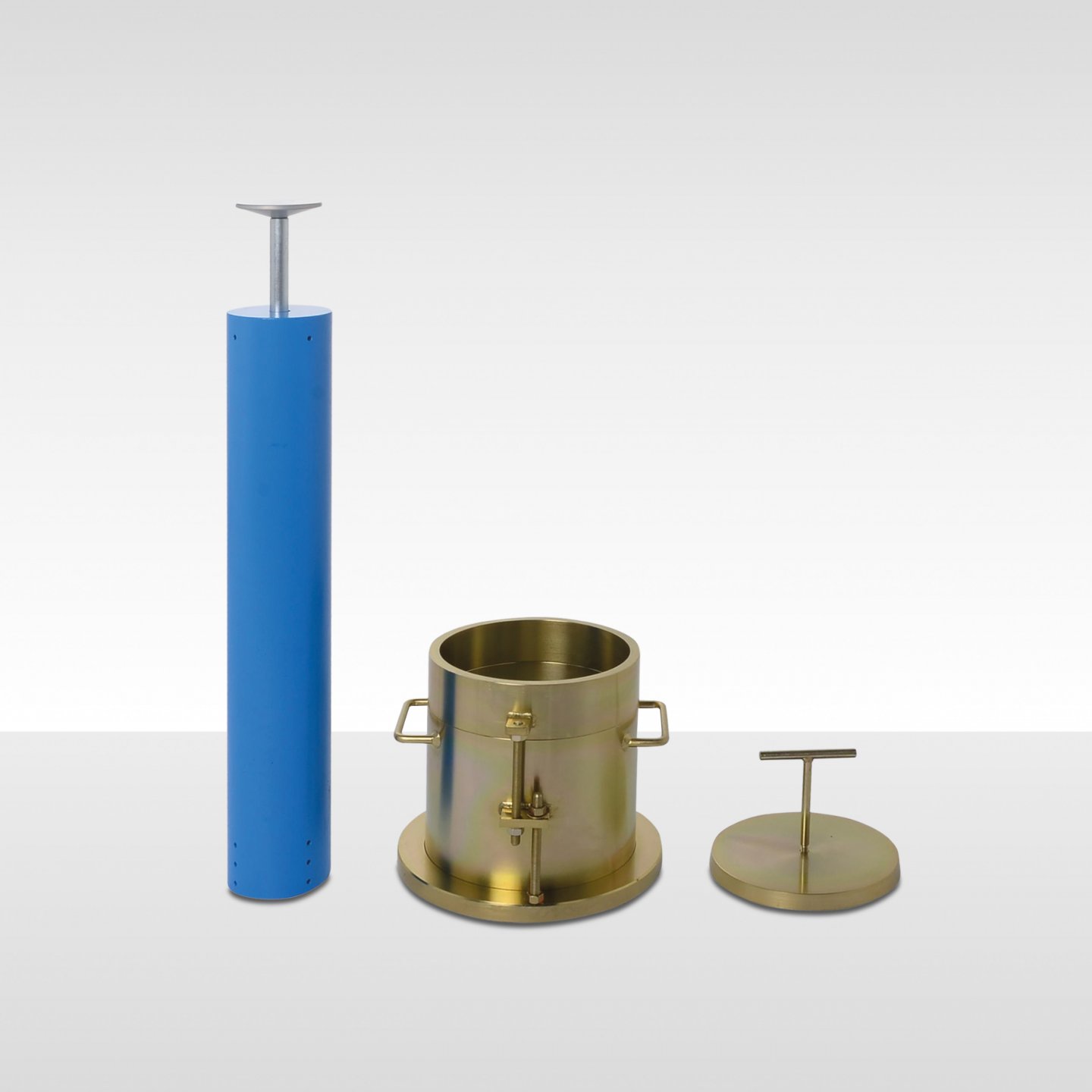
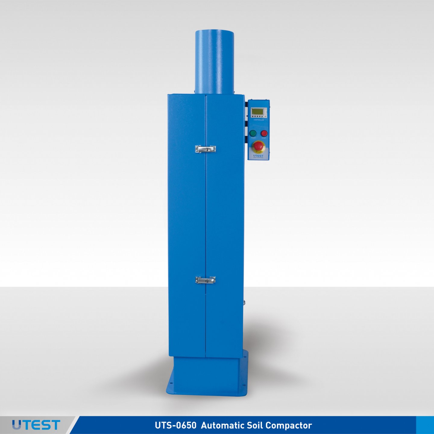
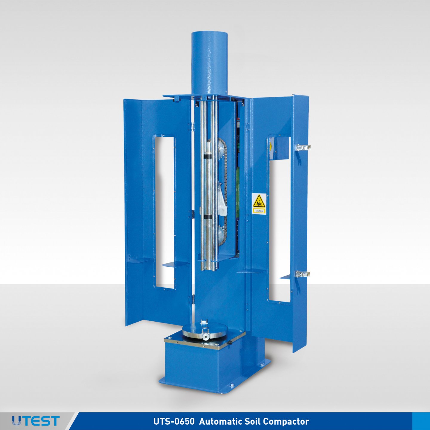
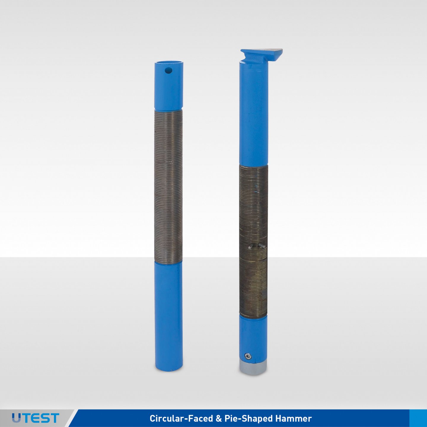
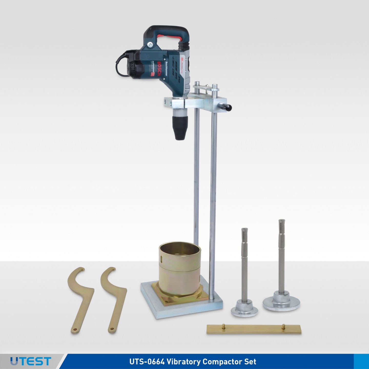
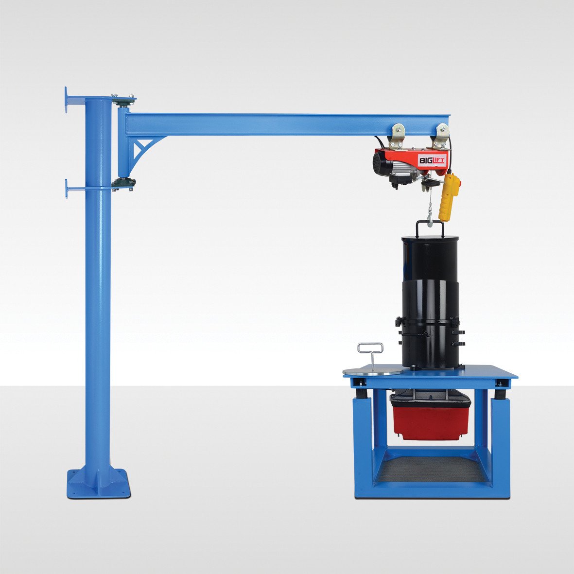
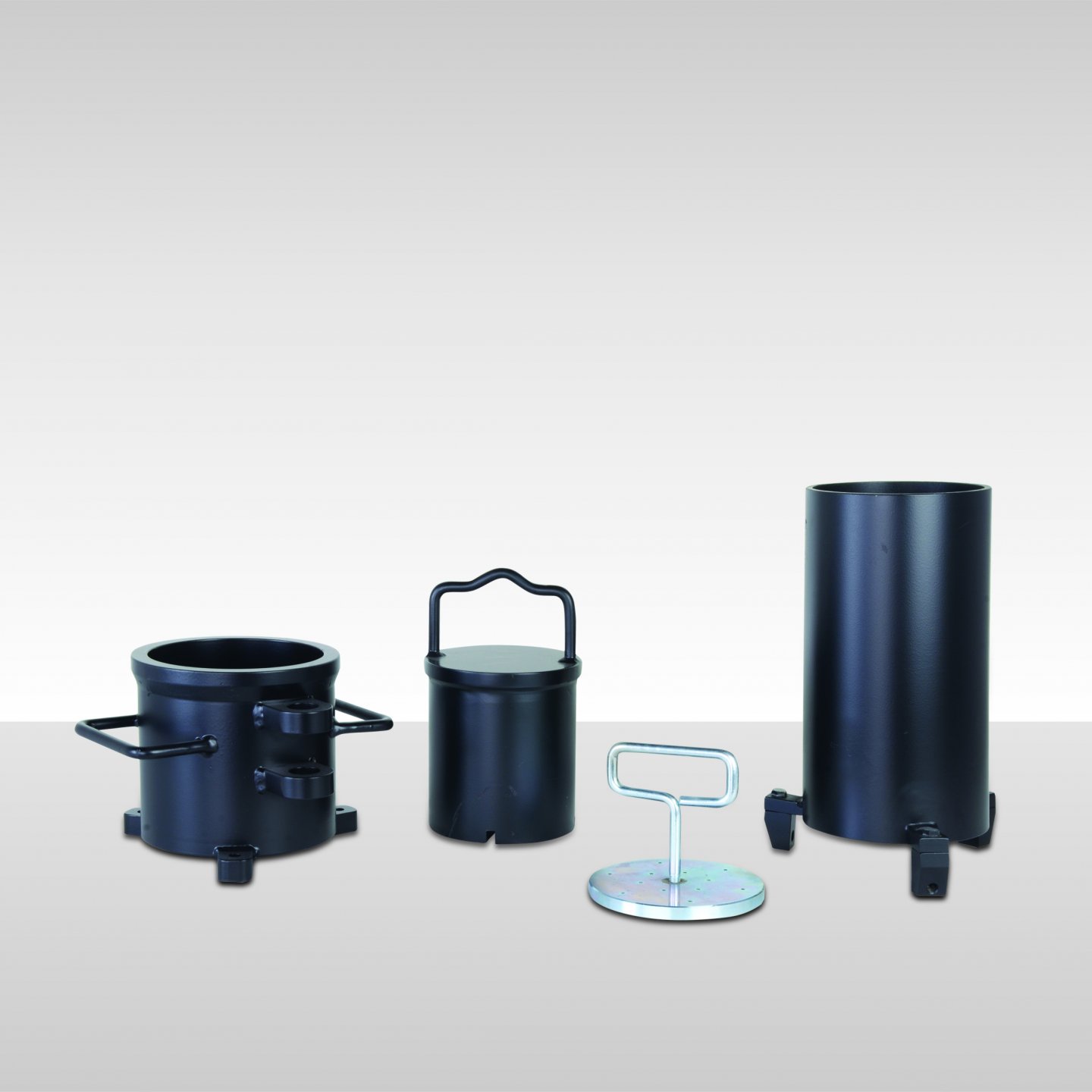
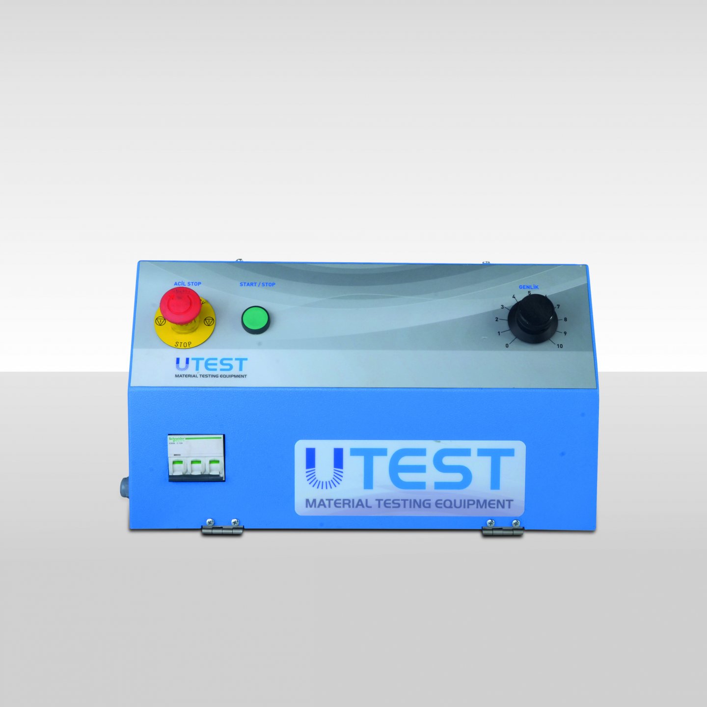
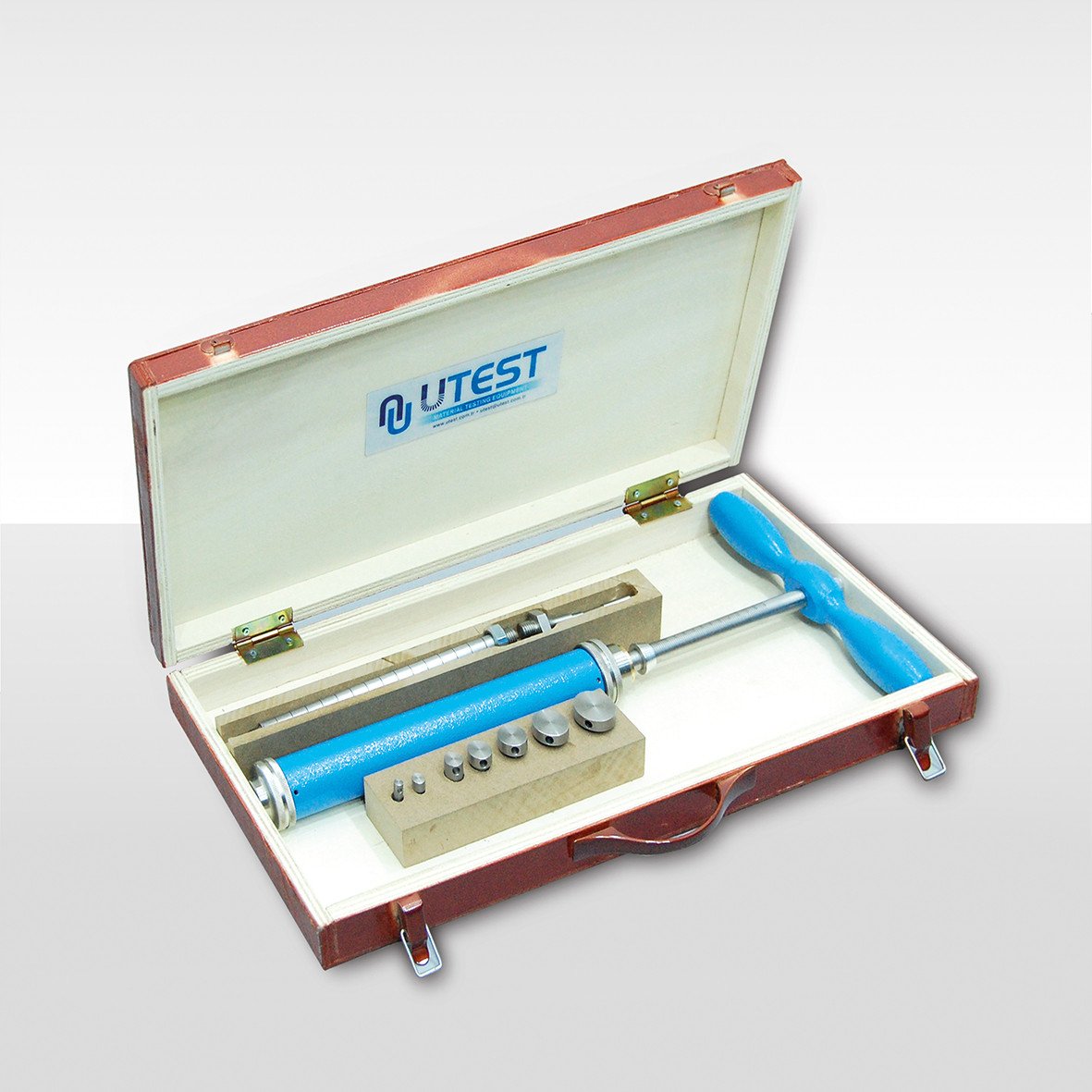
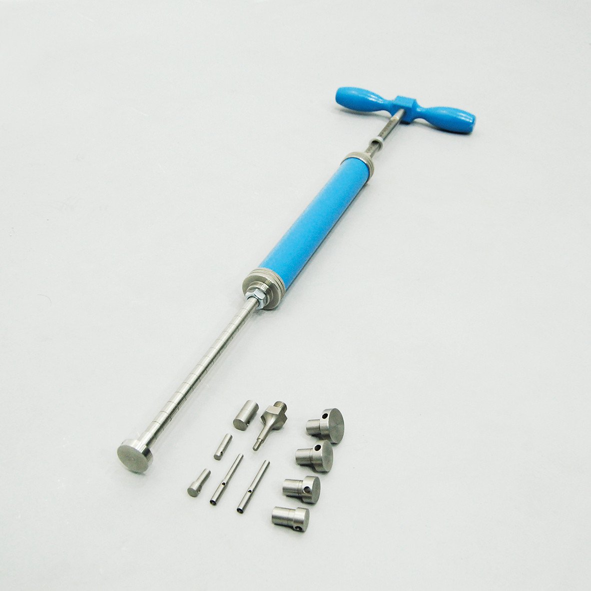
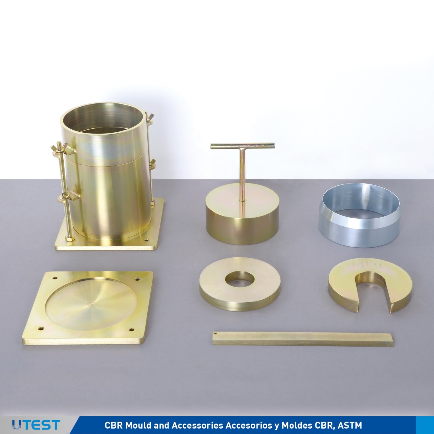
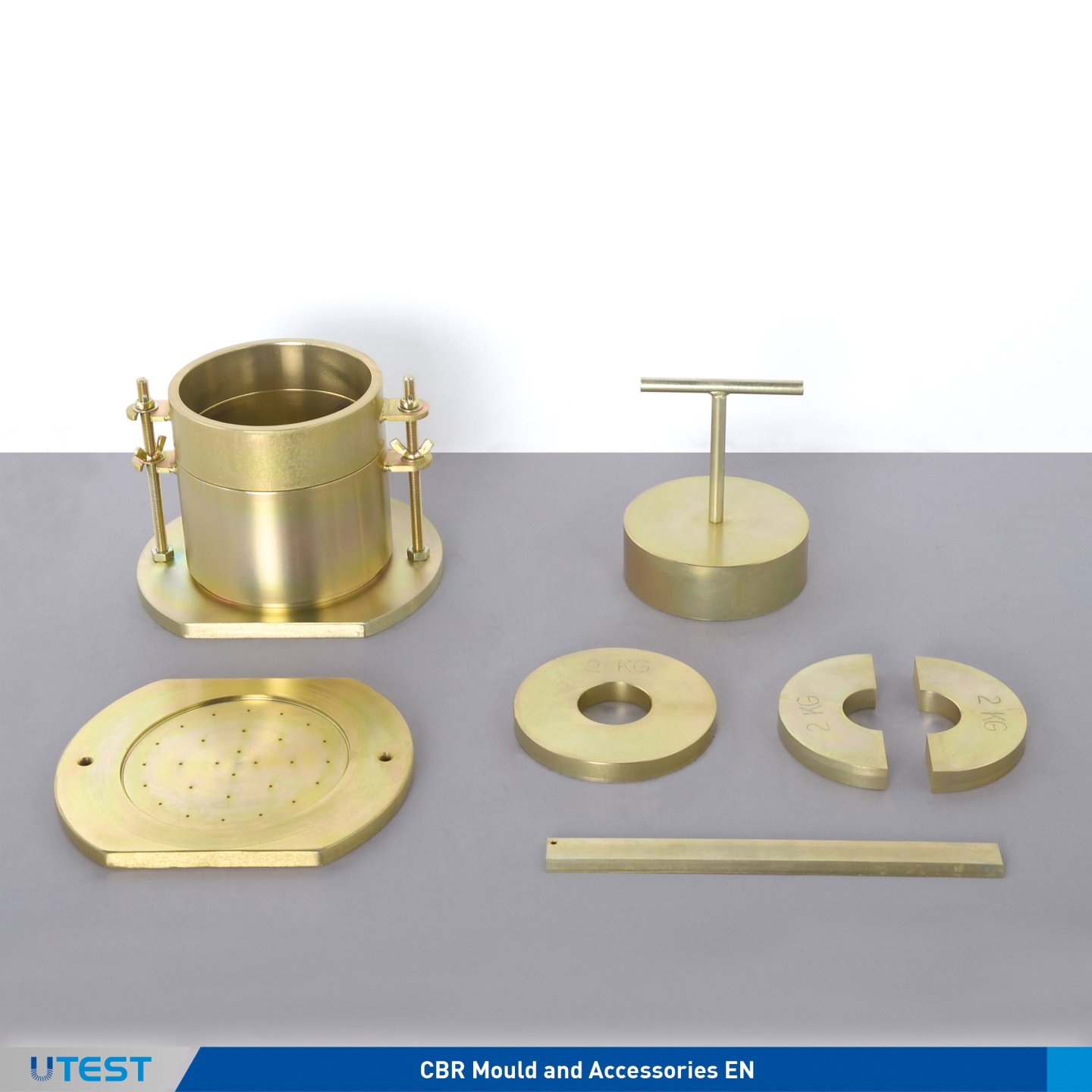
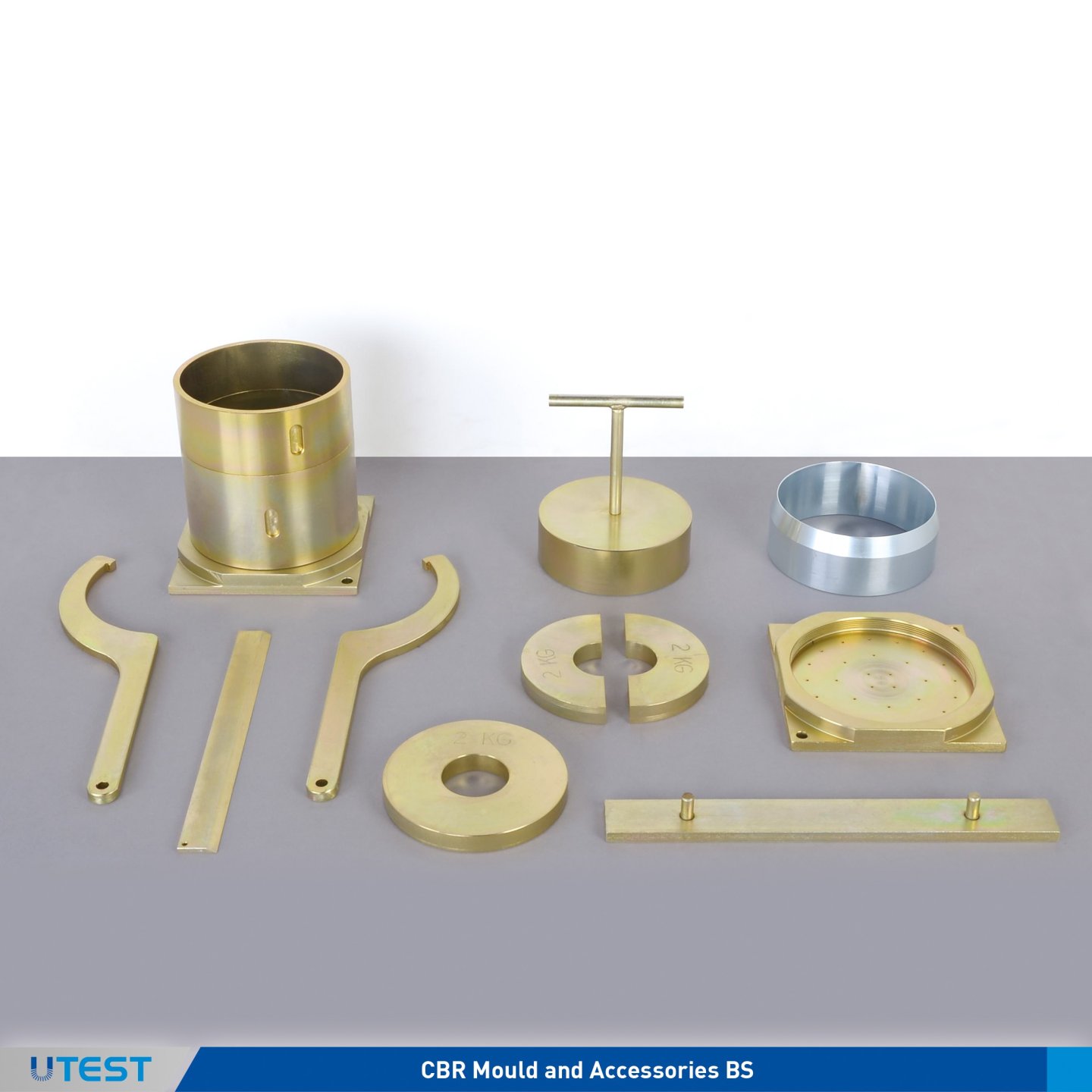
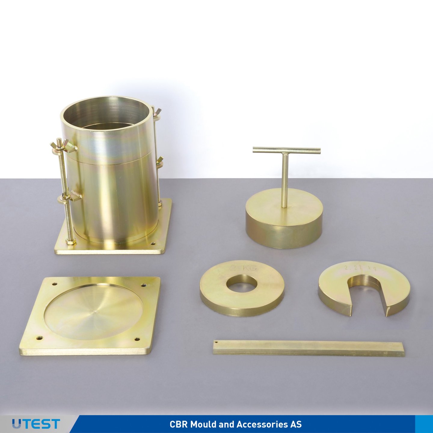
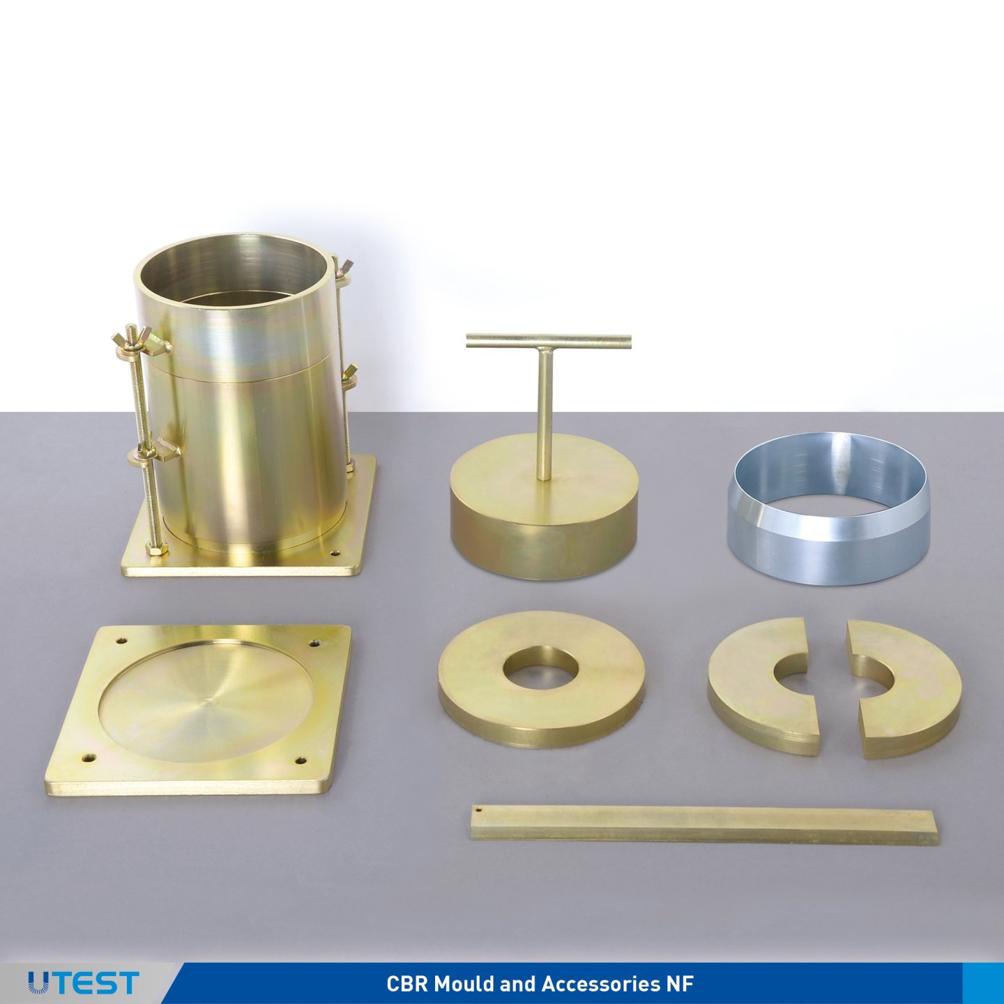
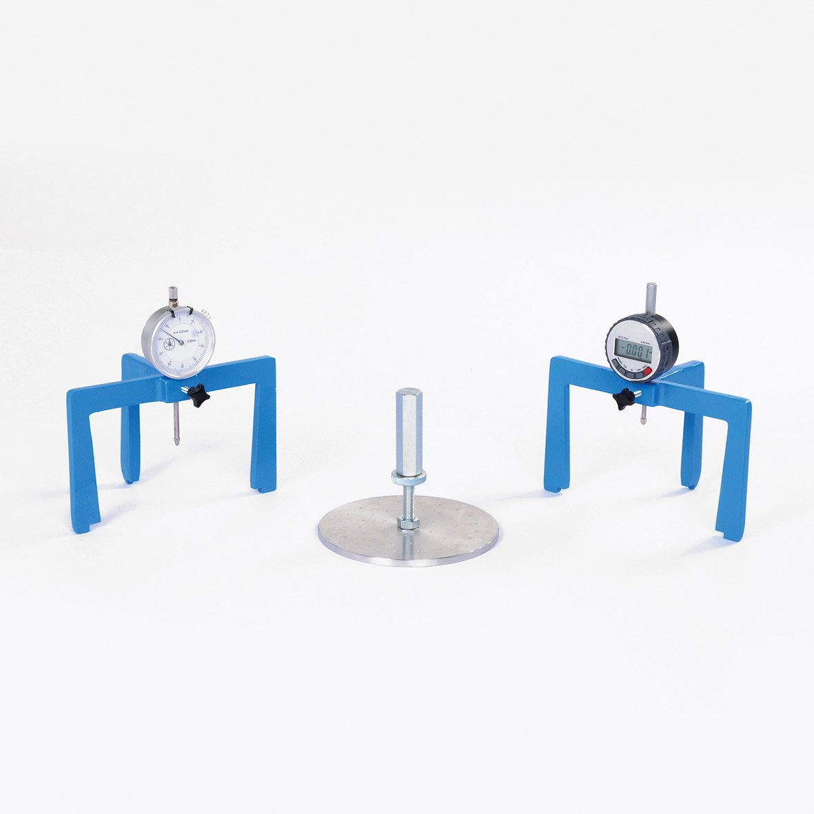
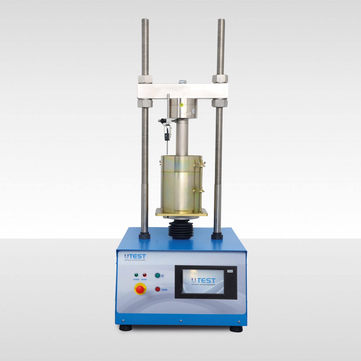
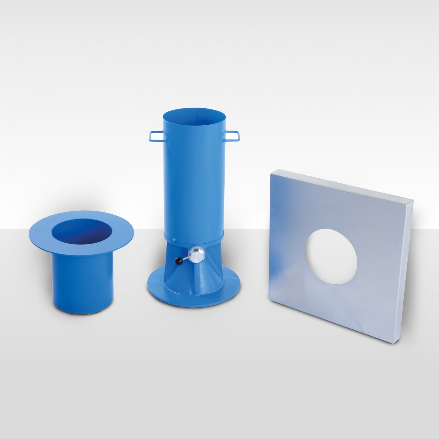
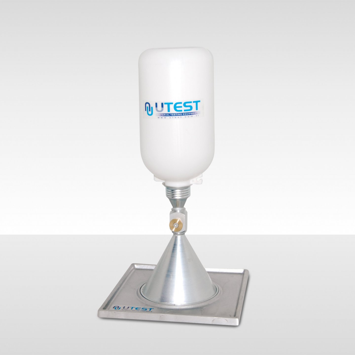
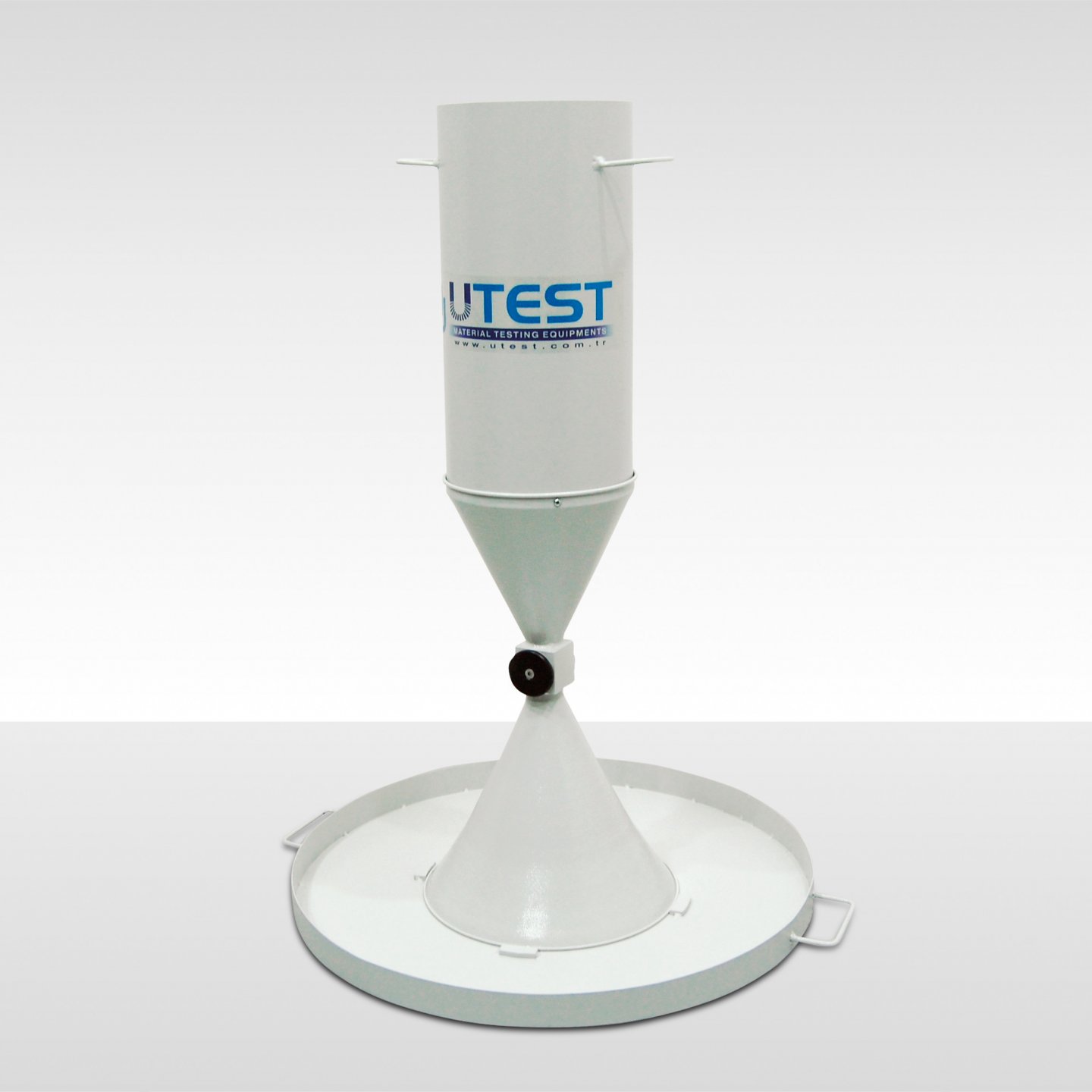
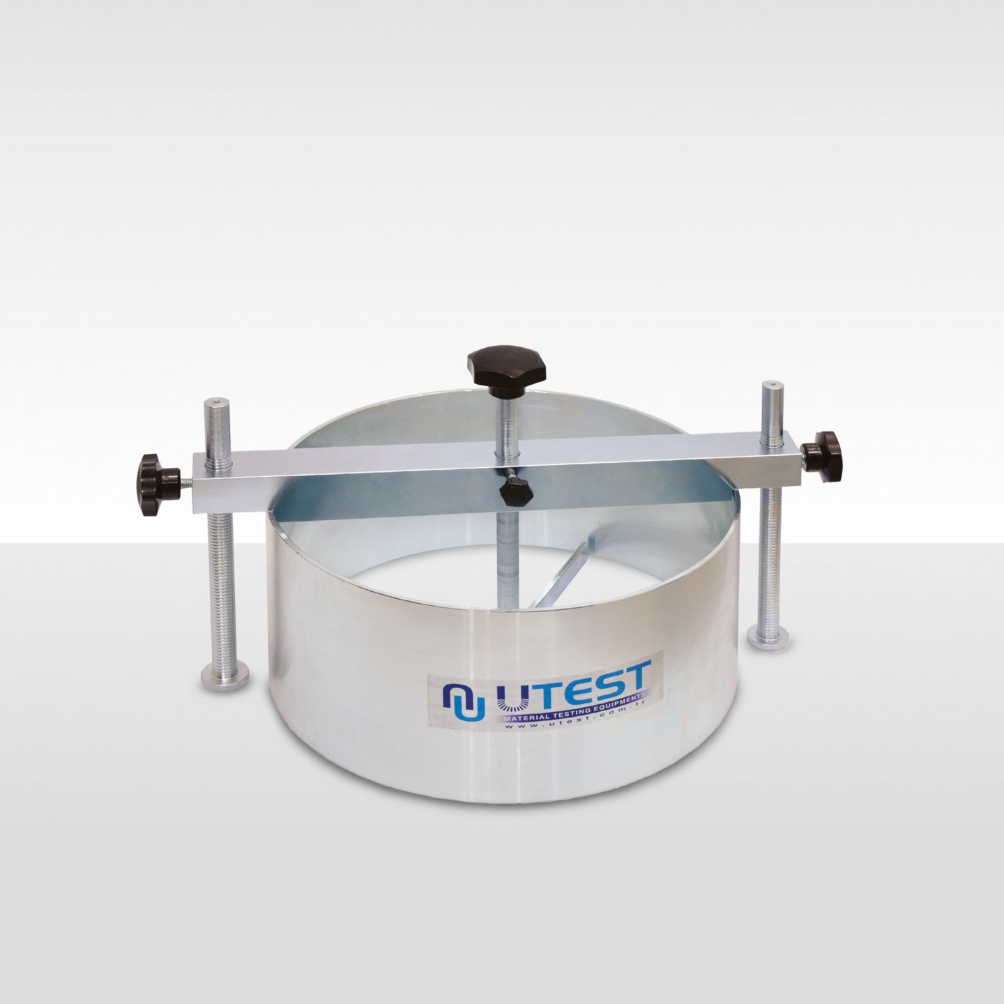
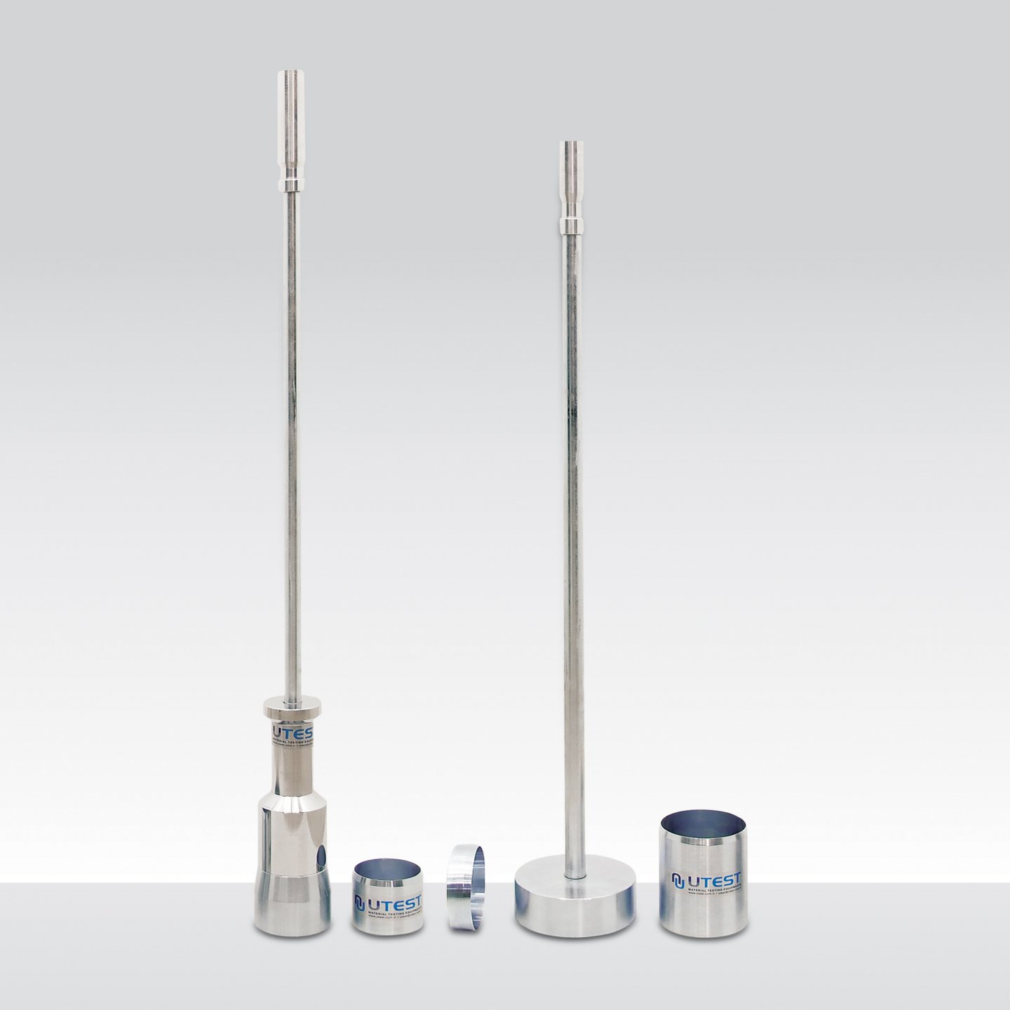
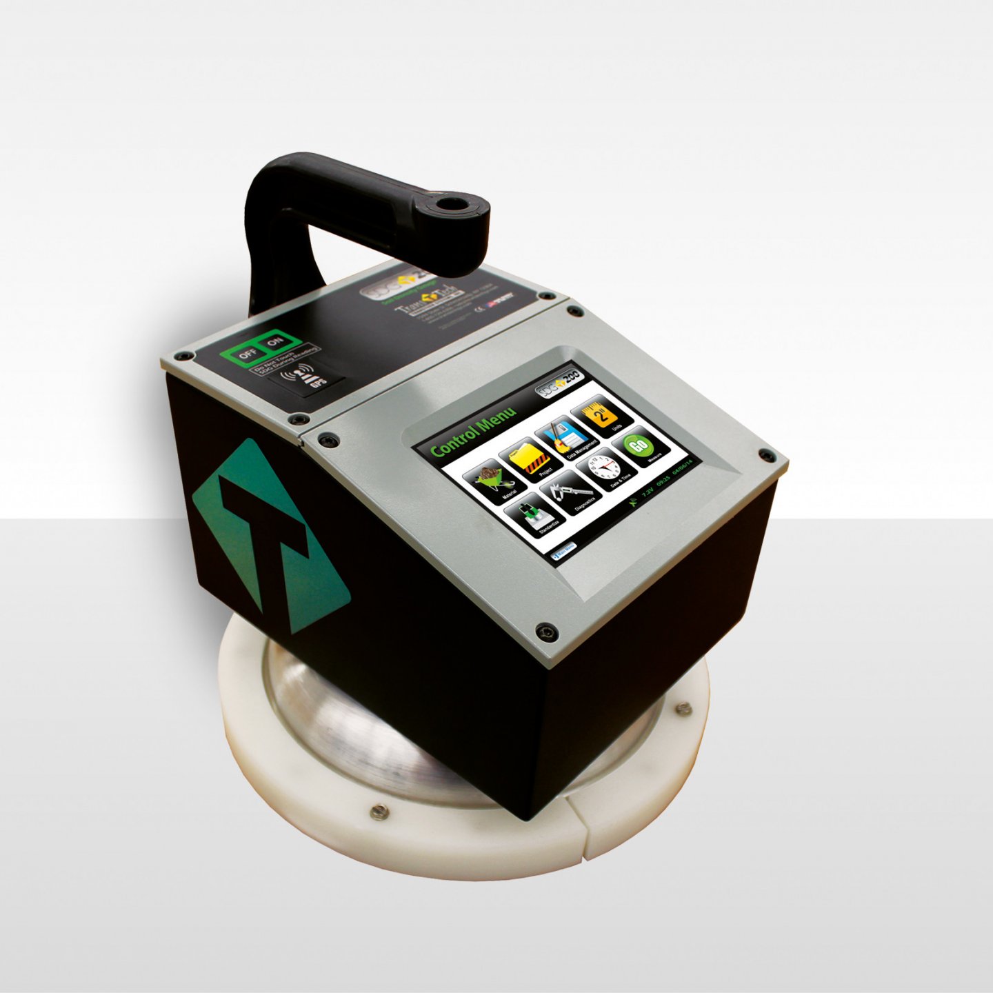
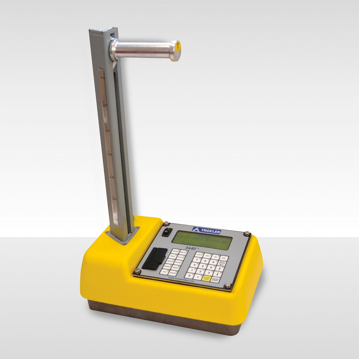
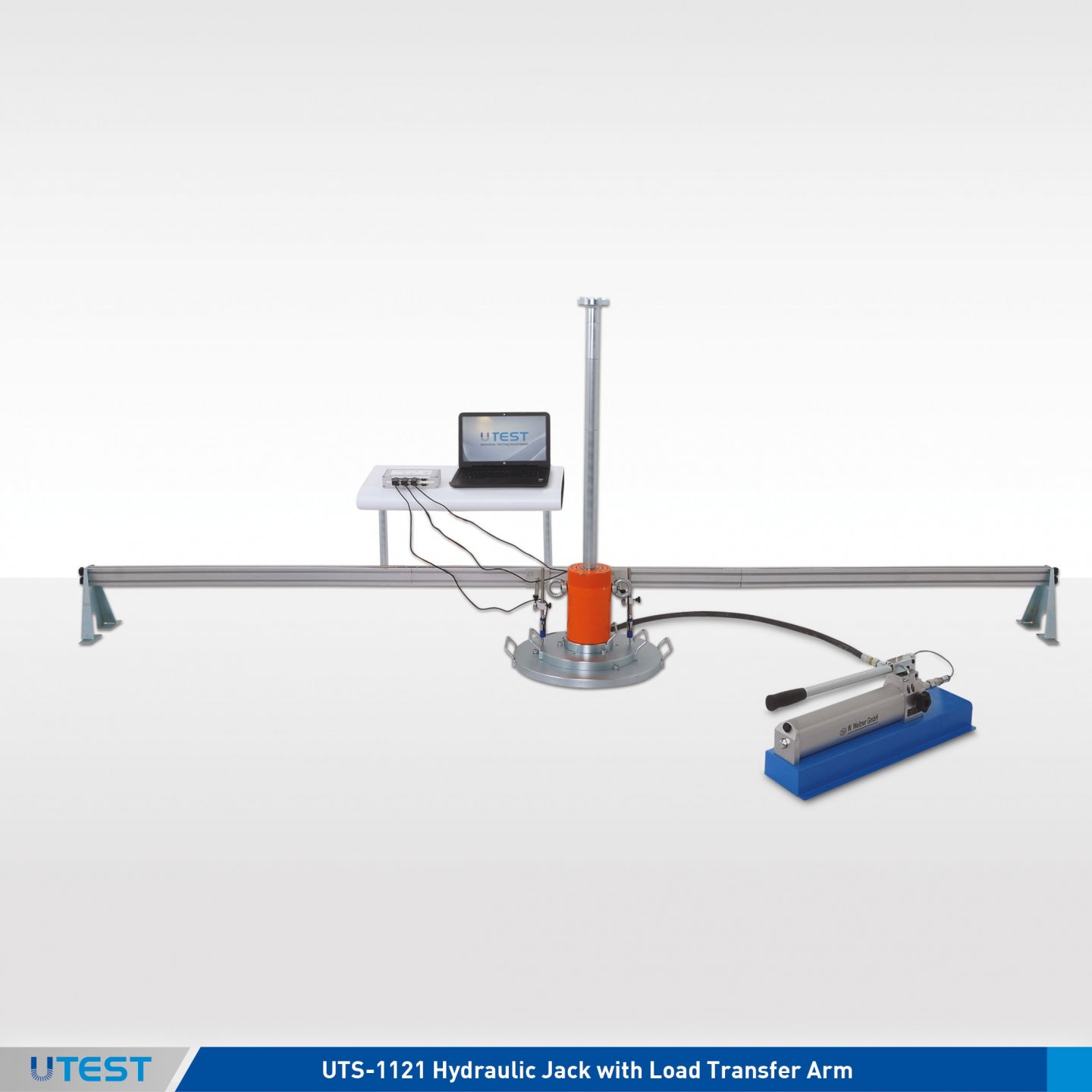
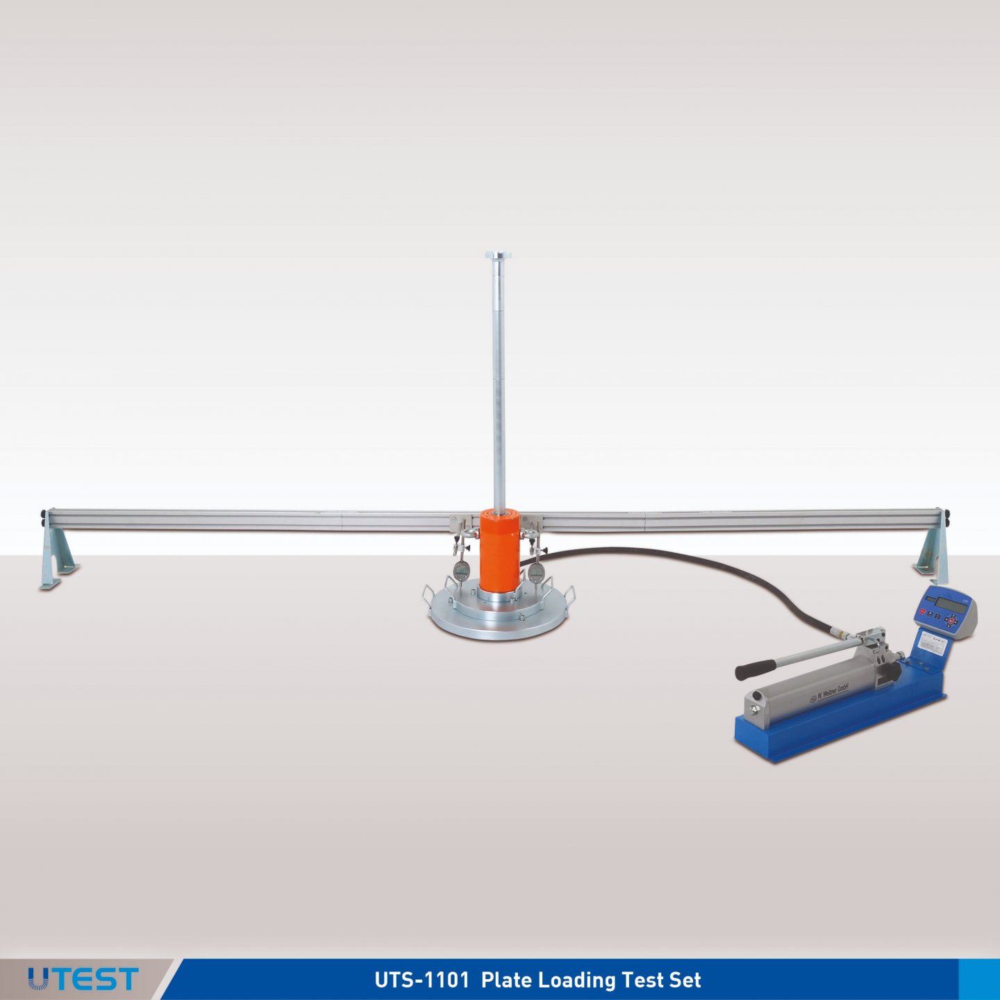
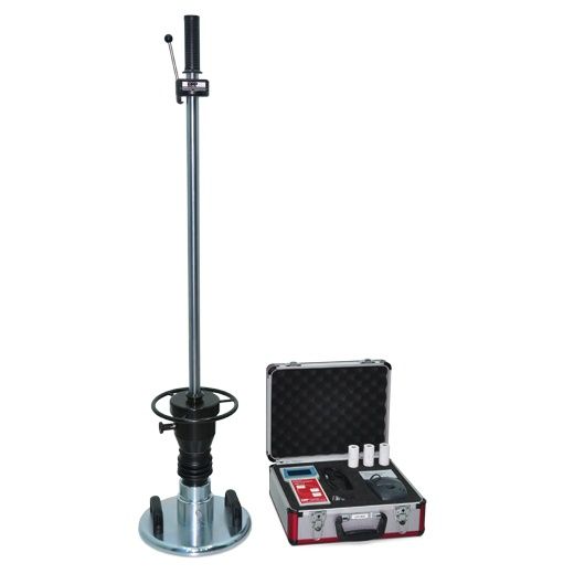
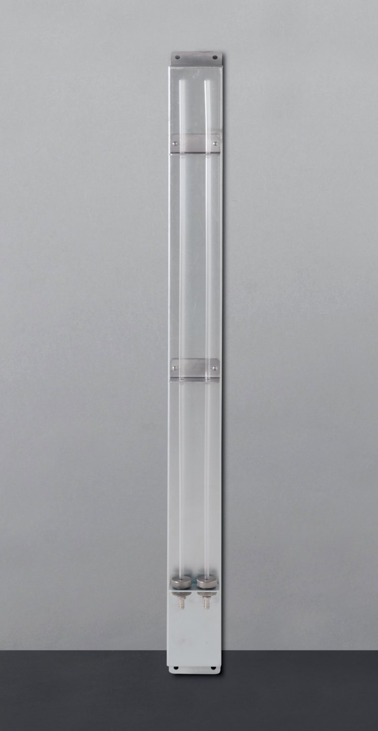
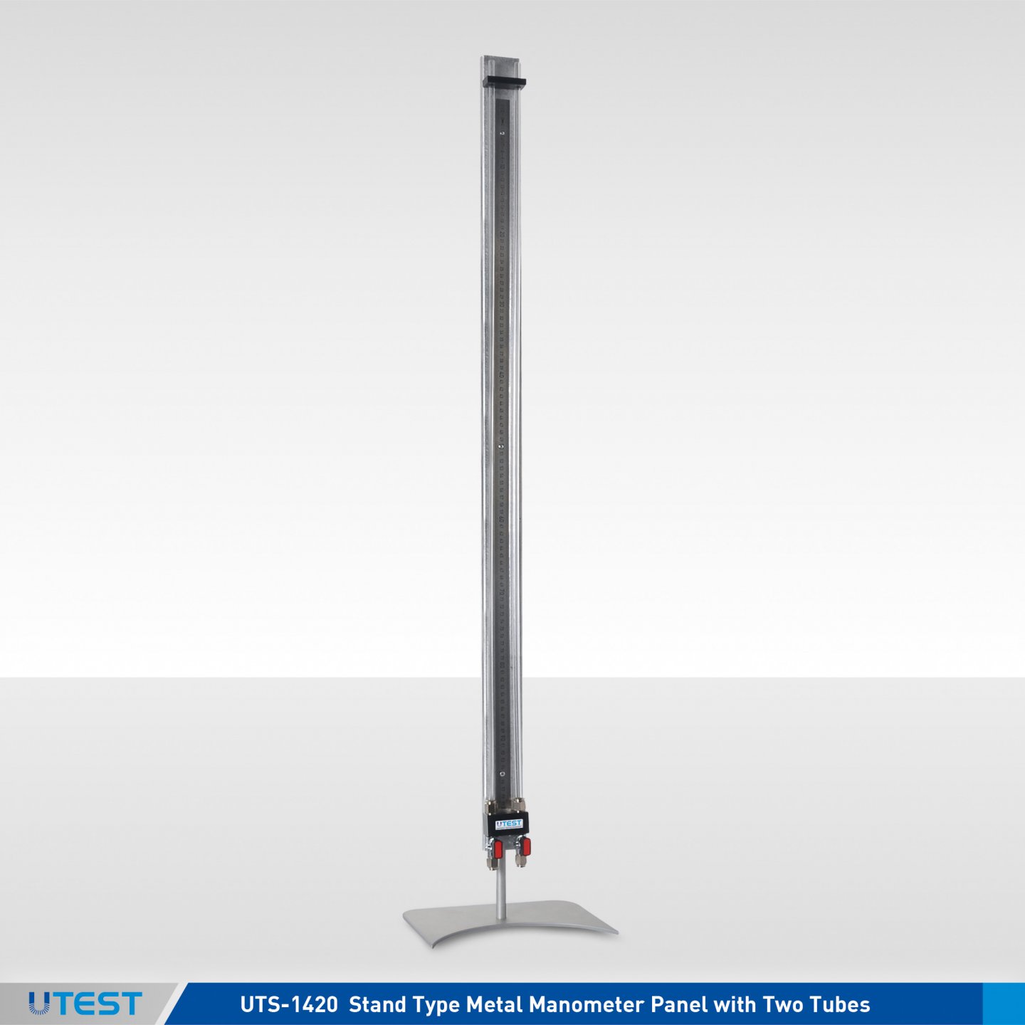
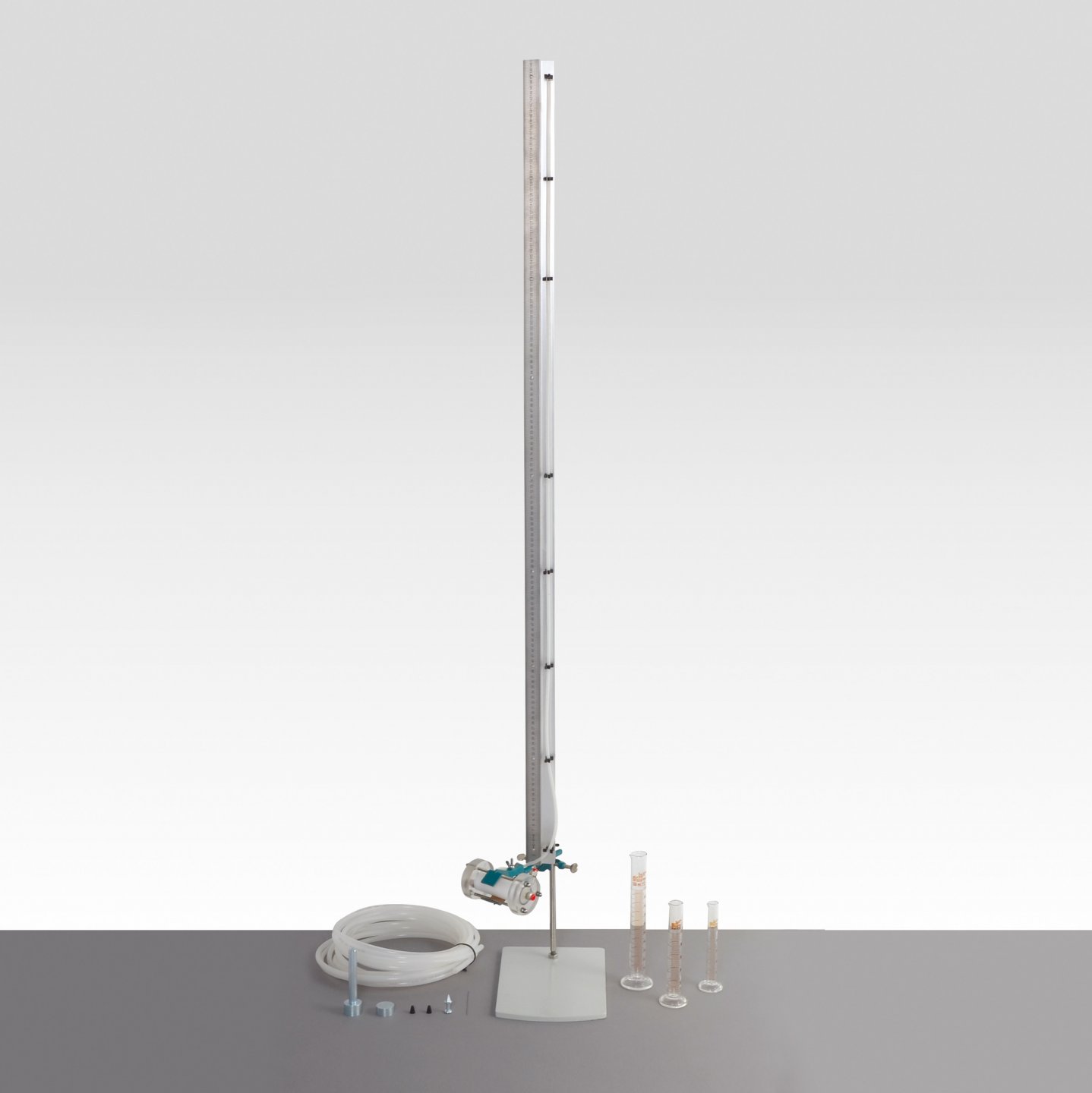
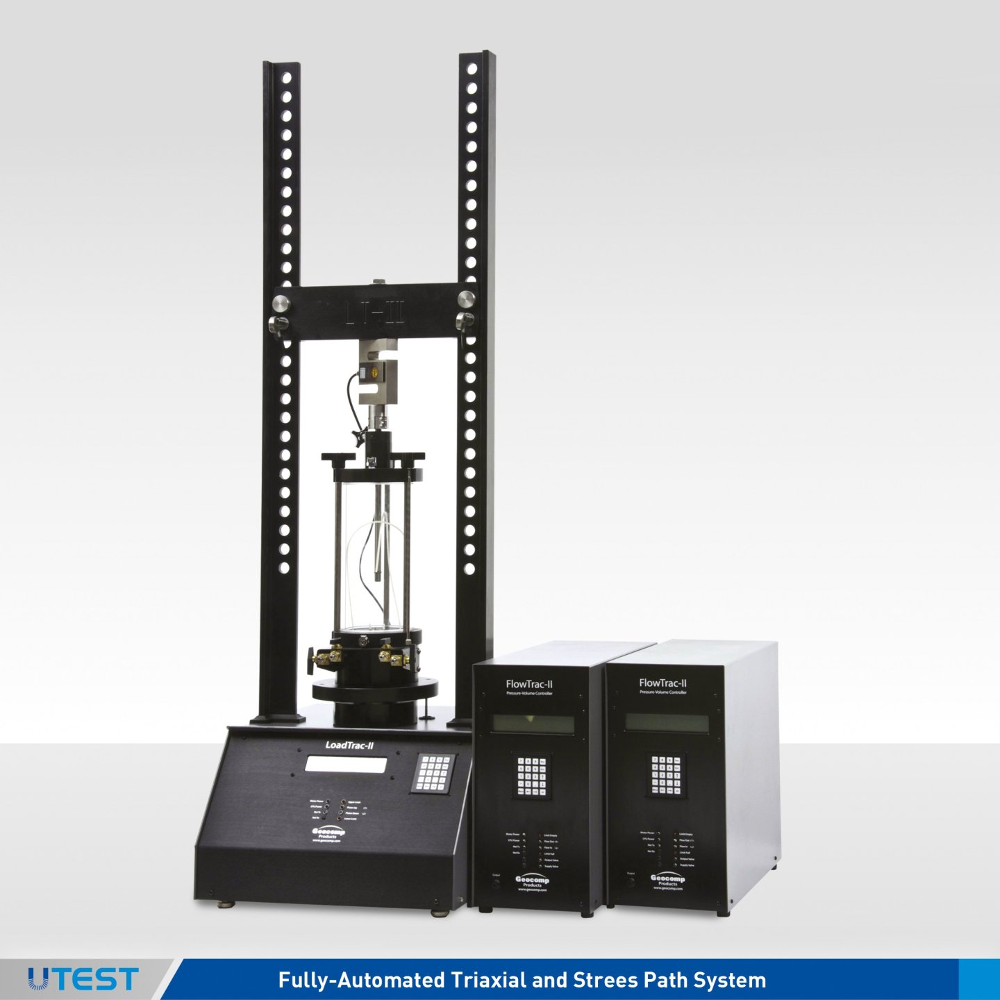
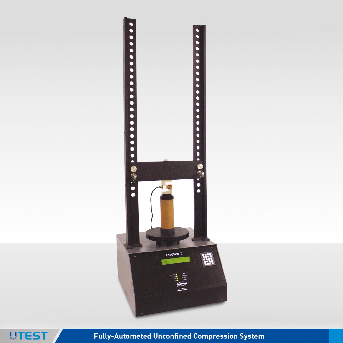
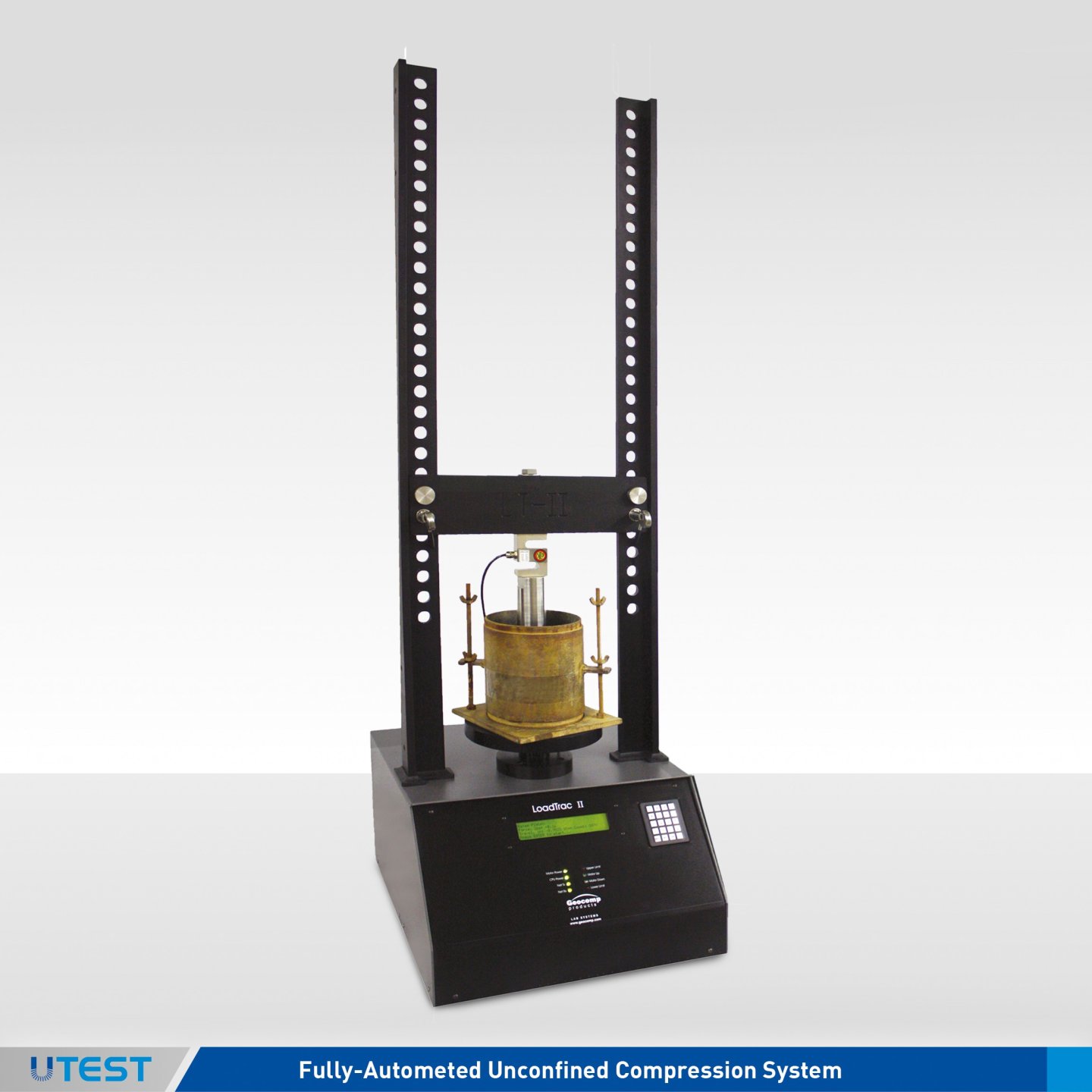
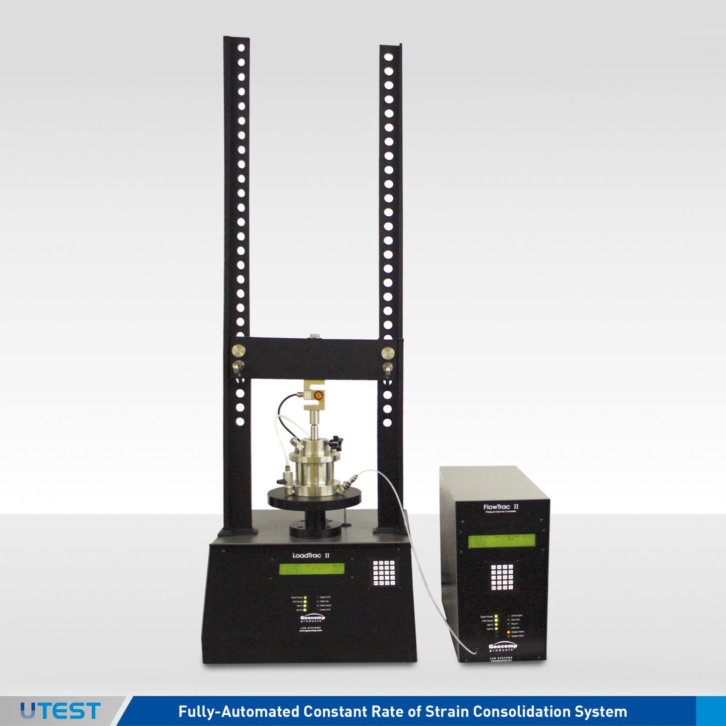
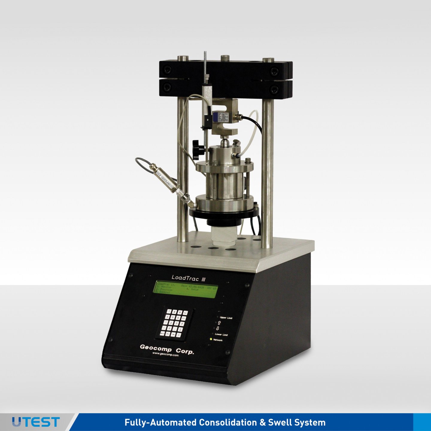
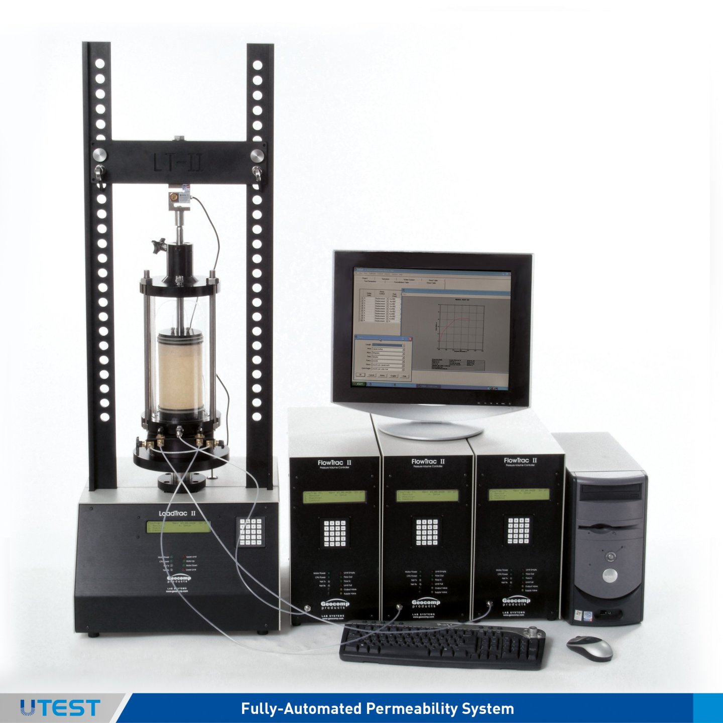
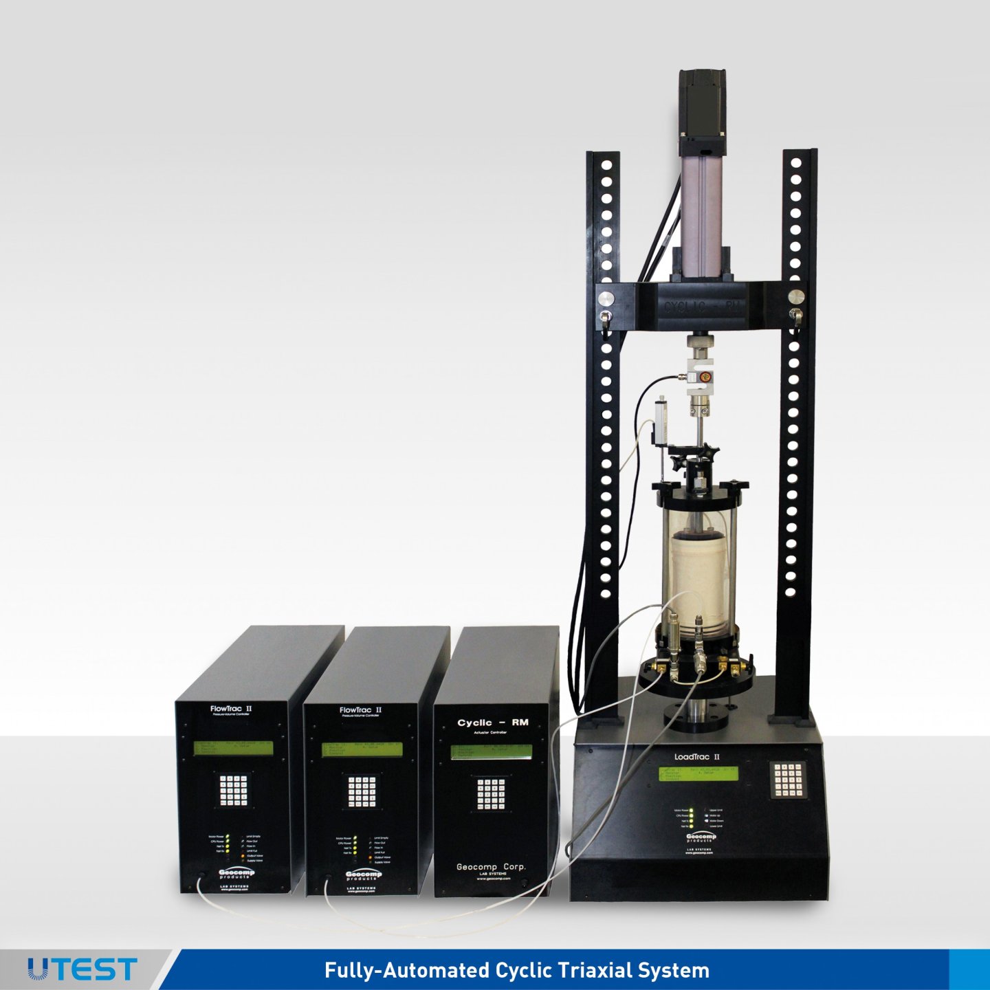
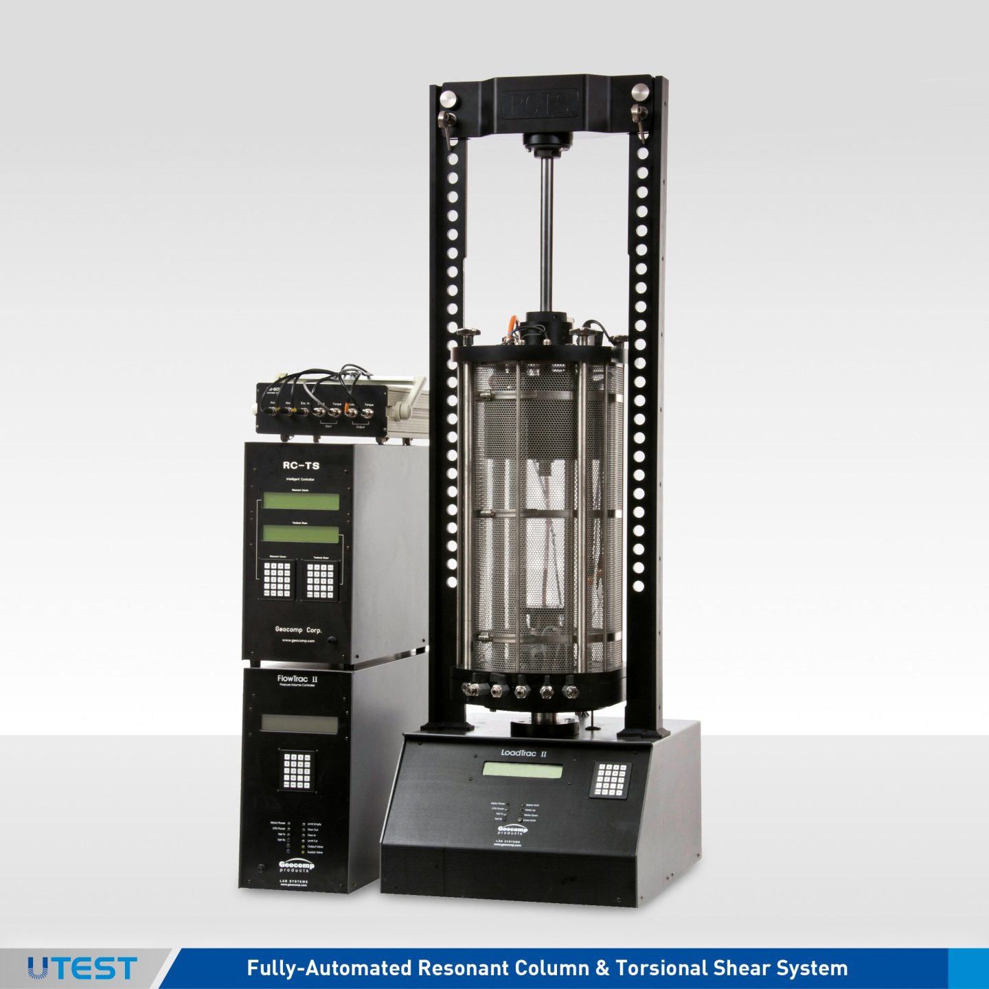
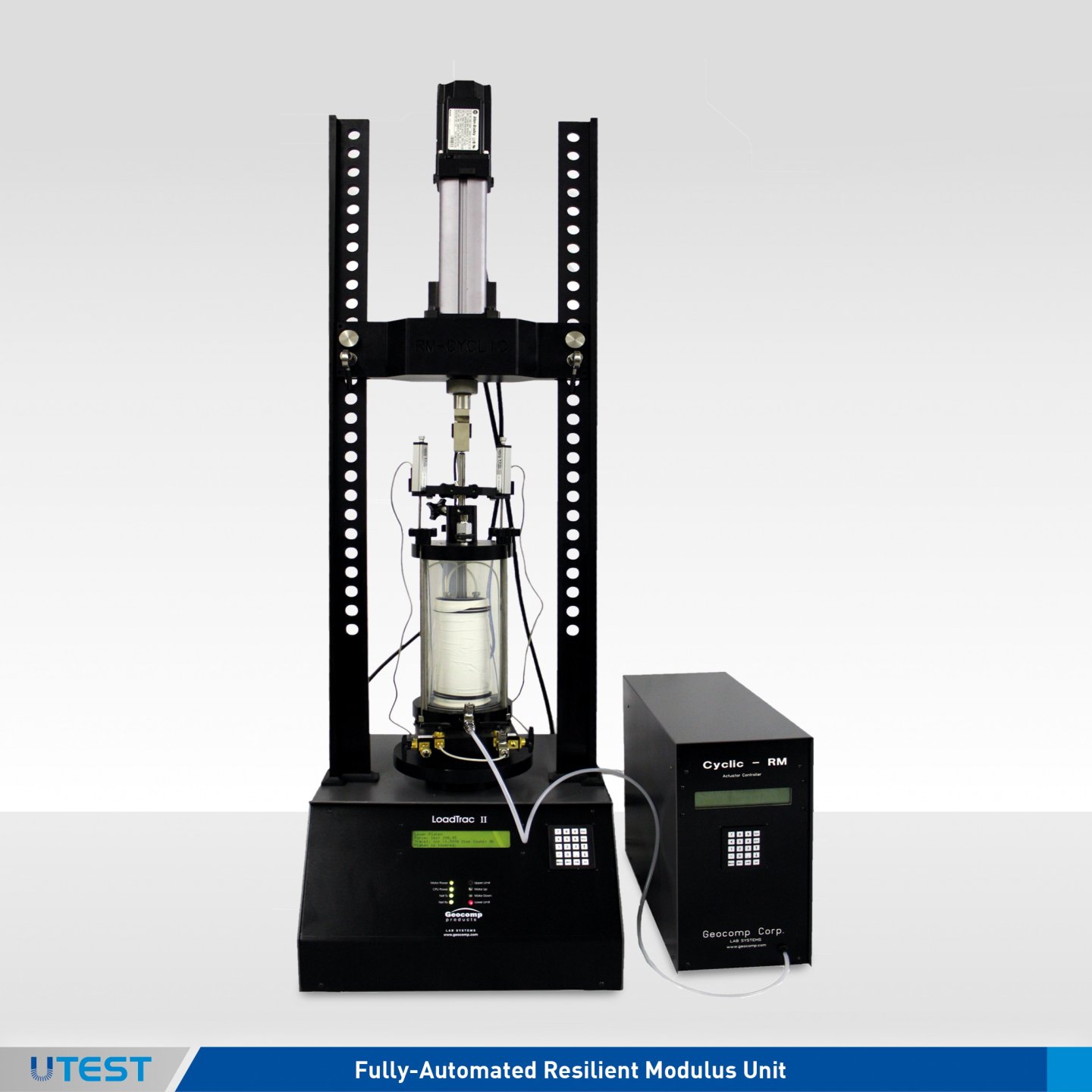
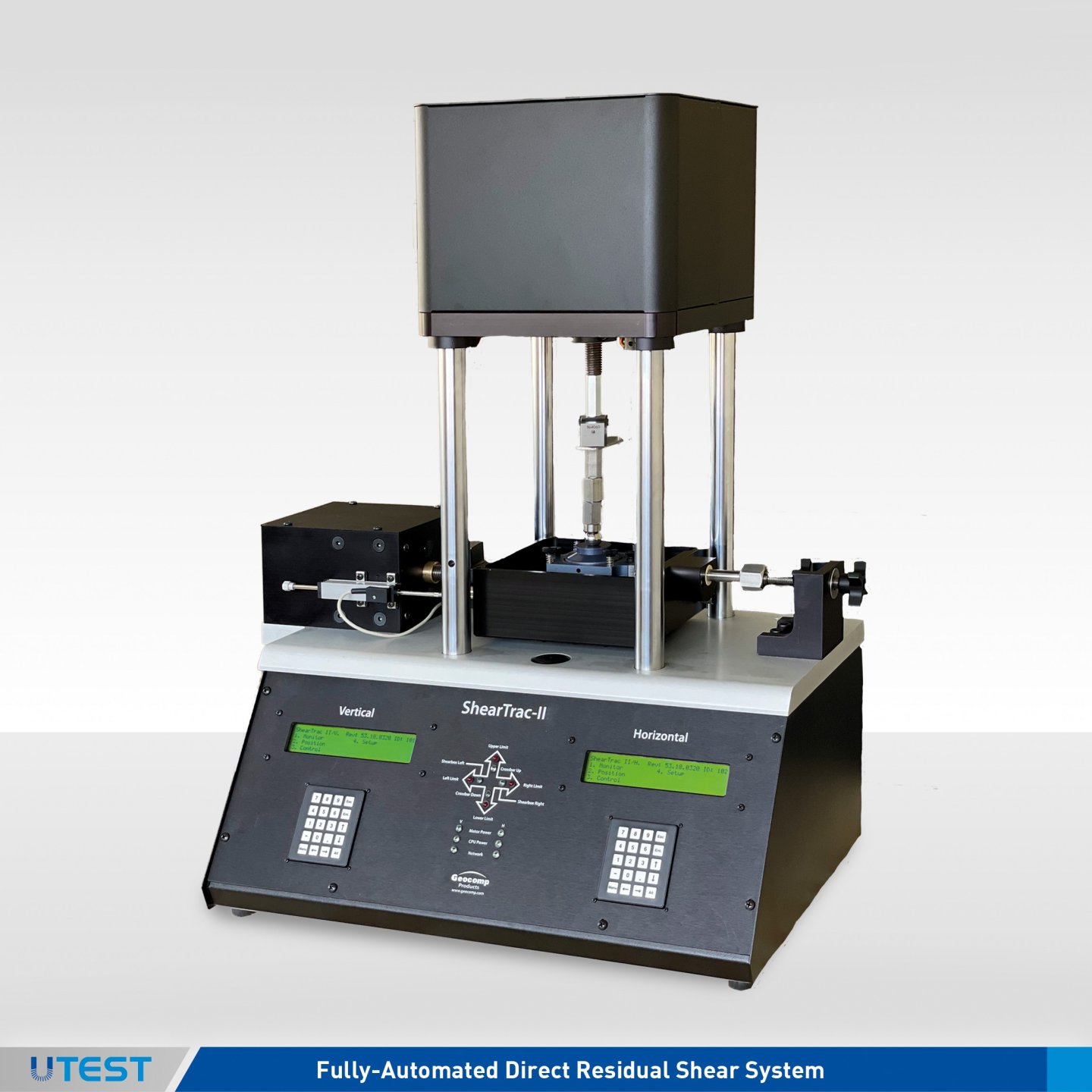
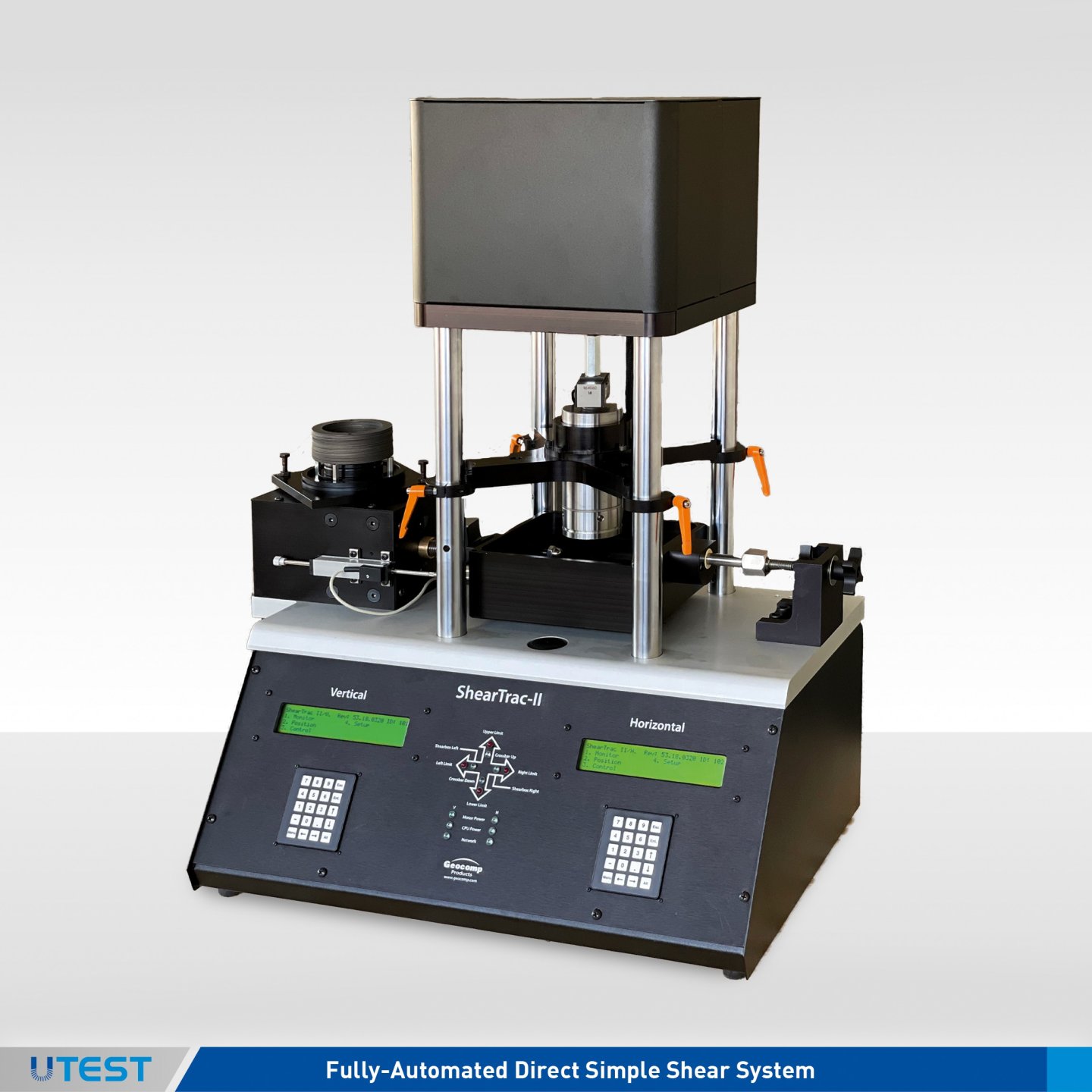
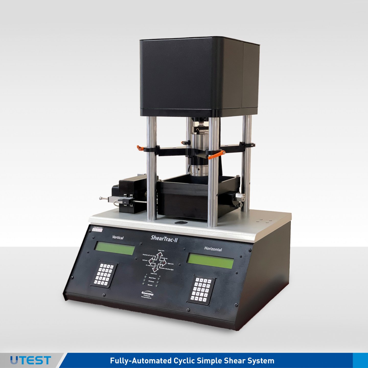
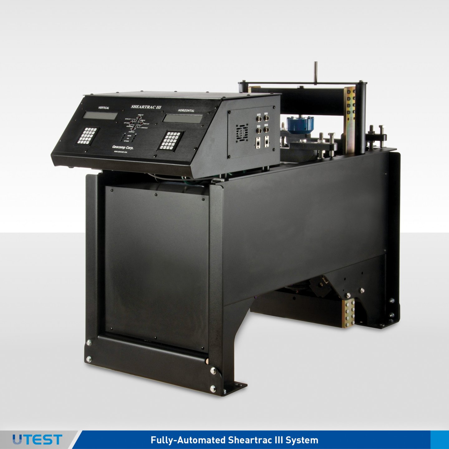